WO2017149904A1 - Cathéter de défibrillation intracardiaque - Google Patents
Cathéter de défibrillation intracardiaque Download PDFInfo
- Publication number
- WO2017149904A1 WO2017149904A1 PCT/JP2016/087524 JP2016087524W WO2017149904A1 WO 2017149904 A1 WO2017149904 A1 WO 2017149904A1 JP 2016087524 W JP2016087524 W JP 2016087524W WO 2017149904 A1 WO2017149904 A1 WO 2017149904A1
- Authority
- WO
- WIPO (PCT)
- Prior art keywords
- lead wire
- lumen
- group
- sub
- electrode group
- Prior art date
- Legal status (The legal status is an assumption and is not a legal conclusion. Google has not performed a legal analysis and makes no representation as to the accuracy of the status listed.)
- Ceased
Links
Images

Classifications
-
- A—HUMAN NECESSITIES
- A61—MEDICAL OR VETERINARY SCIENCE; HYGIENE
- A61N—ELECTROTHERAPY; MAGNETOTHERAPY; RADIATION THERAPY; ULTRASOUND THERAPY
- A61N1/00—Electrotherapy; Circuits therefor
- A61N1/18—Applying electric currents by contact electrodes
- A61N1/32—Applying electric currents by contact electrodes alternating or intermittent currents
- A61N1/38—Applying electric currents by contact electrodes alternating or intermittent currents for producing shock effects
- A61N1/39—Heart defibrillators
- A61N1/3956—Implantable devices for applying electric shocks to the heart, e.g. for cardioversion
-
- A—HUMAN NECESSITIES
- A61—MEDICAL OR VETERINARY SCIENCE; HYGIENE
- A61N—ELECTROTHERAPY; MAGNETOTHERAPY; RADIATION THERAPY; ULTRASOUND THERAPY
- A61N1/00—Electrotherapy; Circuits therefor
- A61N1/02—Details
- A61N1/04—Electrodes
- A61N1/05—Electrodes for implantation or insertion into the body, e.g. heart electrode
- A61N1/056—Transvascular endocardial electrode systems
- A61N1/0563—Transvascular endocardial electrode systems specially adapted for defibrillation or cardioversion
-
- A—HUMAN NECESSITIES
- A61—MEDICAL OR VETERINARY SCIENCE; HYGIENE
- A61M—DEVICES FOR INTRODUCING MEDIA INTO, OR ONTO, THE BODY; DEVICES FOR TRANSDUCING BODY MEDIA OR FOR TAKING MEDIA FROM THE BODY; DEVICES FOR PRODUCING OR ENDING SLEEP OR STUPOR
- A61M25/00—Catheters; Hollow probes
- A61M25/0043—Catheters; Hollow probes characterised by structural features
- A61M25/005—Catheters; Hollow probes characterised by structural features with embedded materials for reinforcement, e.g. wires, coils, braids
-
- A—HUMAN NECESSITIES
- A61—MEDICAL OR VETERINARY SCIENCE; HYGIENE
- A61M—DEVICES FOR INTRODUCING MEDIA INTO, OR ONTO, THE BODY; DEVICES FOR TRANSDUCING BODY MEDIA OR FOR TAKING MEDIA FROM THE BODY; DEVICES FOR PRODUCING OR ENDING SLEEP OR STUPOR
- A61M25/00—Catheters; Hollow probes
- A61M25/0067—Catheters; Hollow probes characterised by the distal end, e.g. tips
- A61M25/0082—Catheter tip comprising a tool
-
- A—HUMAN NECESSITIES
- A61—MEDICAL OR VETERINARY SCIENCE; HYGIENE
- A61N—ELECTROTHERAPY; MAGNETOTHERAPY; RADIATION THERAPY; ULTRASOUND THERAPY
- A61N1/00—Electrotherapy; Circuits therefor
- A61N1/02—Details
- A61N1/04—Electrodes
- A61N1/05—Electrodes for implantation or insertion into the body, e.g. heart electrode
-
- A—HUMAN NECESSITIES
- A61—MEDICAL OR VETERINARY SCIENCE; HYGIENE
- A61N—ELECTROTHERAPY; MAGNETOTHERAPY; RADIATION THERAPY; ULTRASOUND THERAPY
- A61N1/00—Electrotherapy; Circuits therefor
- A61N1/02—Details
- A61N1/04—Electrodes
- A61N1/05—Electrodes for implantation or insertion into the body, e.g. heart electrode
- A61N1/056—Transvascular endocardial electrode systems
- A61N1/057—Anchoring means; Means for fixing the head inside the heart
-
- A—HUMAN NECESSITIES
- A61—MEDICAL OR VETERINARY SCIENCE; HYGIENE
- A61N—ELECTROTHERAPY; MAGNETOTHERAPY; RADIATION THERAPY; ULTRASOUND THERAPY
- A61N1/00—Electrotherapy; Circuits therefor
- A61N1/02—Details
- A61N1/04—Electrodes
- A61N1/05—Electrodes for implantation or insertion into the body, e.g. heart electrode
- A61N1/0587—Epicardial electrode systems; Endocardial electrodes piercing the pericardium
-
- A—HUMAN NECESSITIES
- A61—MEDICAL OR VETERINARY SCIENCE; HYGIENE
- A61N—ELECTROTHERAPY; MAGNETOTHERAPY; RADIATION THERAPY; ULTRASOUND THERAPY
- A61N1/00—Electrotherapy; Circuits therefor
- A61N1/18—Applying electric currents by contact electrodes
- A61N1/32—Applying electric currents by contact electrodes alternating or intermittent currents
- A61N1/38—Applying electric currents by contact electrodes alternating or intermittent currents for producing shock effects
- A61N1/39—Heart defibrillators
-
- A—HUMAN NECESSITIES
- A61—MEDICAL OR VETERINARY SCIENCE; HYGIENE
- A61M—DEVICES FOR INTRODUCING MEDIA INTO, OR ONTO, THE BODY; DEVICES FOR TRANSDUCING BODY MEDIA OR FOR TAKING MEDIA FROM THE BODY; DEVICES FOR PRODUCING OR ENDING SLEEP OR STUPOR
- A61M25/00—Catheters; Hollow probes
- A61M25/0067—Catheters; Hollow probes characterised by the distal end, e.g. tips
- A61M25/0082—Catheter tip comprising a tool
- A61M2025/0095—Catheter tip comprising a tool being one or more needles protruding from the distal tip and which are not used for injection nor for electro-stimulation, e.g. for fixation purposes
-
- A—HUMAN NECESSITIES
- A61—MEDICAL OR VETERINARY SCIENCE; HYGIENE
- A61M—DEVICES FOR INTRODUCING MEDIA INTO, OR ONTO, THE BODY; DEVICES FOR TRANSDUCING BODY MEDIA OR FOR TAKING MEDIA FROM THE BODY; DEVICES FOR PRODUCING OR ENDING SLEEP OR STUPOR
- A61M2205/00—General characteristics of the apparatus
- A61M2205/05—General characteristics of the apparatus combined with other kinds of therapy
- A61M2205/054—General characteristics of the apparatus combined with other kinds of therapy with electrotherapy
-
- A—HUMAN NECESSITIES
- A61—MEDICAL OR VETERINARY SCIENCE; HYGIENE
- A61M—DEVICES FOR INTRODUCING MEDIA INTO, OR ONTO, THE BODY; DEVICES FOR TRANSDUCING BODY MEDIA OR FOR TAKING MEDIA FROM THE BODY; DEVICES FOR PRODUCING OR ENDING SLEEP OR STUPOR
- A61M25/00—Catheters; Hollow probes
- A61M25/0021—Catheters; Hollow probes characterised by the form of the tubing
- A61M25/0023—Catheters; Hollow probes characterised by the form of the tubing by the form of the lumen, e.g. cross-section, variable diameter
- A61M25/0026—Multi-lumen catheters with stationary elements
-
- A—HUMAN NECESSITIES
- A61—MEDICAL OR VETERINARY SCIENCE; HYGIENE
- A61M—DEVICES FOR INTRODUCING MEDIA INTO, OR ONTO, THE BODY; DEVICES FOR TRANSDUCING BODY MEDIA OR FOR TAKING MEDIA FROM THE BODY; DEVICES FOR PRODUCING OR ENDING SLEEP OR STUPOR
- A61M25/00—Catheters; Hollow probes
- A61M25/01—Introducing, guiding, advancing, emplacing or holding catheters
- A61M25/0105—Steering means as part of the catheter or advancing means; Markers for positioning
- A61M25/0133—Tip steering devices
- A61M25/0136—Handles therefor
Definitions
- the present invention relates to an intracardiac defibrillation catheter that is inserted into the heart chamber to remove atrial fibrillation.
- an insulating tube member having a multi-lumen structure having a multi-lumen structure, a handle connected to the proximal end of the tube member, and the tube member
- a first DC electrode group composed of a plurality of ring-shaped electrodes mounted on the distal end region of the first DC electrode group, and a second DC electrode composed of a plurality of ring-shaped electrodes mounted on the tube member spaced from the first DC electrode group toward the proximal end side
- a first lead wire group composed of a lead wire connected to each of the electrodes constituting the first DC electrode group, and a lead wire connected to each of the electrodes constituting the second DC electrode group
- a lead wire group, and the first lead wire group and the second lead wire group extend to different lumens of the tube member, and when performing defibrillation, the first DC And polar permanent, the said first 2DC electrode group has proposed the intracardia
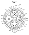
- FIG. 7 is a cross-sectional view of a distal end region of a tube member constituting the defibrillation catheter described in Patent Document 1, and this tube member 110 includes four lumens (a first lumen 111, a second lumen 112, A third lumen 113 and a fourth lumen 114) are formed.
- 115 is a resin tube made of fluororesin that divides the lumen
- 116 is an inner part made of low-hardness nylon elastomer
- 117 is an outer part made of high-hardness nylon elastomer
- 118 is a braid. It is a stainless steel wire forming.
- the first lumen 111 includes a first lead wire group 141 ⁇ / b> G including lead wires 141 connected to each of the electrodes constituting the first DC electrode group, and the second lumen 112.
- the second lead wire group 142G consisting of the lead wires 142 connected to each of the electrodes constituting the second DC electrode group extends, and the third lumen 113 is connected to each of the potential measuring electrodes.
- a third lead wire group 143G consisting of the lead wires 143 and a fourth lead wire group 144G consisting of the lead wires 144 extend, and an operation wire 171 extends to the fourth lumen 114.
- the first lead wire group 141G and the second lead wire group 142G extend to different lumens of the tube members (the first lumen 111 and the second lumen 112), respectively.
- a voltage necessary for intracavitary defibrillation is applied, a short circuit occurs between the first lead wire group 141G (first DC electrode group) and the second lead wire group 142G (second DC electrode group). Can be prevented.
- An intracardiac defibrillation catheter is inserted from the inferior vena cava into the right atrium and inserted into the coronary sinus ostium (approach from the inferior vena cava). It is less invasive compared to conventional procedures (approach from the superior vena cava) that are inserted into the sinus ostium.
- a lumen (guide wire lumen) through which the guide wire can be inserted is formed in the tube member of the intracardiac defibrillation catheter.
- the tube member having the guide wire lumen in addition to the lumen for extending the lead wire and the operation wire has a higher space occupancy rate (lower resin occupancy rate) and extends the first lead wire group.
- the thickness of the resin that separates the lumen to be extended from the lumen that extends the second lead wire group is also reduced, so that when the voltage required for defibrillation is applied, the first lead wire group (first DC electrode group) And a short circuit between the second lead wire group (second DC electrode group).
- the defibrillation catheter provided with the tube member having a high space ratio (low resin ratio) due to having the guide wire lumen is inferior in torque transmission.
- a first object of the present invention can be inserted into a target site in a heart chamber along a guide wire, and includes a first lead group (first electrode group) and a second lead group (second electrode group). It is an object of the present invention to provide an intracardiac defibrillation catheter that can reliably prevent a short circuit between the two and the like.
- the second object of the present invention is to provide an intracardiac defibrillation capable of exhibiting excellent torque transmission performance even though the ratio of the resin constituting the tube member is reduced by having the guide wire lumen.
- An arterial catheter will be provided.
- An intracardiac defibrillation catheter of the present invention includes an insulating tube member, a handle connected to the proximal end of the tube member, and a plurality of ring electrodes attached to a distal end region of the tube member
- a first DC electrode group consisting of: a second DC electrode group consisting of a plurality of ring electrodes spaced from the first DC electrode group toward the proximal end side and attached to the distal end region of the tube member; and the first DC electrode group
- the tube member is a multi-lumen structure having a central lumen through which a guide wire can be inserted and at least a pair of sub-lumen
- the lead wires constituting the first lead wire group and the lead wires constituting the second lead wire group are opposed to each other across the central lumen.
- the lead wires constituting the first lead wire group and the lead wires constituting the second lead wire group are sufficiently separated from each other by extending to one and the other of the pair of sublumens arranged in the In this state, the tube member can be completely insulated and isolated.
- the first lead wire group extends to one of the pair of sublumens, and the second lead wire group extends to the other of the pair of sublumens. Preferably present.
- the first lead wire group (all lead wires constituting this) and the second lead wire group (all lead wires constituting this) include The first lead wire group and the second lead wire group are sufficiently separated from each other by extending to one and the other of the pair of sub-lumens arranged so as to face each other across the central lumen. In this state, the tube member can be completely insulated and isolated.
- the lead wires constituting the first lead wire group are divided and extended into a plurality of sublumens, and the lead wires constituting the second lead wire group are The first lead wire group is divided into a plurality of sub-lumens facing each other across the central lumen to each of the plurality of sub-lumens extending the lead wires, and the first lead It is preferable that the lead wire constituting the wire group and the lead wire constituting the second lead wire group do not extend to the sub-lumens adjacent in the circumferential direction.
- the lead wires constituting the first lead wire group and the lead wires constituting the second lead wire group are divided into a plurality of sub-lumens and extend. Even if the lead wires constituting the first lead wire group and the lead wires constituting the second lead wire group do not extend to the sub-lumen adjacent in the circumferential direction, It is possible to reliably prevent a short circuit from occurring between the first lead wire group (first DC electrode group) and the second lead wire group (second DC electrode group).
- the tube member is reinforced by a braid over its entire length, and at least the braid reinforcing the distal end region of the tube member is made of resin. Is preferred. According to the intracardiac defibrillation catheter having such a configuration, since the tube member is reinforced by the braid over the entire length, excellent torque despite having a low resin ratio due to having a central lumen. It can exhibit transmissibility.
- the braid that reinforces the tip region of the tube member is made of resin, a side hole for passing the lead wire of the electrode can be easily formed on the tube wall of the tip region of the tube member, The resin wire exposed on the inner peripheral surface of the side hole does not damage the lead wire inserted through the side hole.
- the tube member is reinforced with a resin braid over the entire length thereof.
- the tube member is reinforced by the braid over the entire length, excellent torque despite having a low resin ratio due to having a central lumen. It can exhibit transmissibility.
- the braid is made of resin, a side hole for passing the lead wire of the electrode can be easily formed in the tube wall of the distal end region of the tube member, and is exposed to the inner peripheral surface of the side hole. The lead wire inserted into the side hole is not damaged by the resin wire. Further, since the braid is made of resin, no short circuit occurs through the braid.
- the tube member (blade tube) reinforced by the resin braid over the entire length can be manufactured by one extrusion molding, for example, the tip portion reinforced by the resin braid and the metal braid. Compared with a blade tube formed by joining a base end portion reinforced by the above, manufacturing is easy. Further, there is no kink that is likely to occur at the tube portion where the constituent material of the braid is switched.
- the catheter can be inserted into a target site in the heart chamber along the guide wire, and can be inserted into the coronary sinus ostium by the approach from the inferior vena cava. It can be done easily.
- it is possible to reliably prevent a short circuit between the first lead wire group (first DC electrode group) and the second lead wire group (second DC electrode group). Can do.
- the ratio of the resin constituting the tube member is reduced by having the central lumen. Nevertheless, excellent torque transmission can be exhibited.
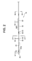
- FIG. 1 is a plan view showing a defibrillation catheter according to a first embodiment of the present invention. It is explanatory drawing which shows the front-end
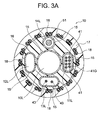
- FIG. 3 is a transverse sectional view (AA sectional view) of the distal end region of the defibrillation catheter shown in FIG. 2.
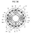
- FIG. 3 is a transverse sectional view (BB sectional view) of the distal end region of the defibrillation catheter shown in FIG. It is a top view which shows the defibrillation catheter which concerns on 2nd Embodiment of this invention.
- FIG. 5 is a transverse sectional view (CC sectional view) of the distal end region of the defibrillation catheter shown in FIG. 4. It is a transverse cross section showing the tip field of the defibrillation catheter concerning a 3rd embodiment of the present invention. It is a cross-sectional view showing a distal end region of a conventional defibrillation catheter.
- a defibrillation catheter 100 of this embodiment shown in FIGS. 1 to 3 includes a multi-lumen tube 10, a handle 20 connected to the proximal end thereof, and a distal region of the multi-lumen tube 10.
- a first DC electrode group 31G composed of eight ring-shaped electrodes 31 mounted, and eight ring-shaped electrodes 32 mounted on the distal end region of the multi-lumen tube 10 spaced from the first DC electrode group 31G toward the proximal end side.
- a second DC electrode group 32G, four ring electrodes 33 for potential measurement mounted on the tip region of the multi-lumen tube 10 between the first DC electrode group 31G and the second DC electrode group 32G, and a multi-lumen tube 10 includes a tip 35 attached to the tip of the lead 10 and a lead 41 connected to each of the electrodes 31 constituting the first DC electrode group 31G.
- the first lead wire group 41G, the second lead wire group 42G composed of the lead wires 42 connected to each of the electrodes 32 constituting the second DC electrode group 32G, and the potential measuring ring electrode 33.
- the lumen tube 10 is reinforced by a resin braid 18 over its entire length, and a central lumen 10L serving as a guide wire lumen and a first sub-lumen 11L disposed so as to face each other with the central lumen 10L therebetween.
- a second sub-lumen 12L disposed opposite to the second sub-lumen 12L with the central lumen 10L interposed therebetween;
- the first lead wire group 41G extends to the first sub-lumen 11L
- the second lead wire group 42G extends to the second sub-lumen 12L
- the lead wire 43 Extends to the third sub-lumen 13L.
- the defibrillation catheter 100 of this embodiment includes a multi-lumen tube 10, a handle 20, a first DC electrode group 31G, a second DC electrode group 32G, a ring electrode 33 for potential measurement, a distal tip 35, The first lead wire group 41G, the second lead wire group 42G, and the lead wire 43 are provided.
- the multi-lumen tube 10 constituting the defibrillation catheter 100 is an insulating tube member having a multi-lumen structure.
- the outer diameter of the multi-lumen tube 10 is, for example, 1.2 to 3.3 mm, and is 2.0 mm as a suitable example.
- the tip region of the multi-lumen tube 10 is shown linearly, but the tip region usually has a specific curve shape.
- a curved shape of the tip region examples include those disclosed in JP2012-50673A, JP2012-192124A, and the like, but are not limited thereto.
- Note that such a curved shape of the tip region is a shape when no force is received from the outside. For example, when the multi-lumen tube 10 is passed through a straight lumen, it is deformed linearly, When the lumen tube 10 is passed through a curved lumen, the lumen tube 10 bends according to the shape of the lumen.
- the shape of the tip region can be changed by operating the handle 20 described later.
- the multi-lumen tube 10 constituting the defibrillation catheter 100 of this embodiment includes an inner part 16 made of resin, and an outer part 17 made of resin that covers the inner part 16.
- the multi-lumen tube 10 (inner portion 16) includes a central lumen 10L as a guide wire lumen and four sub-lumens (first sub-lumen 11L, second sub-lumen 12L, and third sub-lumen around the central lumen 10L). 13L and the fourth sub-lumen 14L) are partitioned by the resin tube 15, respectively.
- the diameter of the central lumen 10L is, for example, 0.4 to 1.0 mm, and is 0.75 mm as a preferred example.
- the ratio of the diameter of the central lumen 10L to the outer diameter of the multi-lumen tube 10 is preferably 0.2 or more, and is 0.375 (0.75 / 2.0) as a suitable example.
- the first sub-lumen 11L and the second sub-lumen 12L are arranged to face each other with the central lumen 10L interposed therebetween. Further, the third sub-lumen 13L and the fourth sub-lumen 14L are arranged to face each other with the central lumen 10L interposed therebetween.
- the cross sections of the first sub-lumen 11L, the second sub-bloom 12L, and the third sub-lumen 13L are each of a capsule shape (oblong shape), thereby increasing the outer diameter of the multi-lumen tube 10 more than necessary.
- the area of the lumen lumen can be secured widely, and the assembly work can be simplified.
- Examples of the resin constituting the inner part 16 and the outer part 17 include thermoplastic polyamide-based elastomers, and polyether block amide (PEBAX) is particularly preferable.
- the hardness of the resin constituting the inner portion 16 is preferably 25D to 40D.
- the hardness of the resin constituting the outer portion 17 is preferably 35D to 72D.
- resin which comprises the outer part 17 the thing of the hardness which changes with axial directions normally is used.
- the resin tube 15 defining the lumen is made of a highly insulating fluororesin such as perfluoroalkyl vinyl ether copolymer (PFA) or polytetrafluoroethylene (PTFE).
- PFA perfluoroalkyl vinyl ether copolymer
- PTFE polytetrafluoroethylene
- a resin braid 18 that is a reinforcing material is embedded in the outer portion 17 over the entire length of the multi-lumen tube 10.
- the braid 18 includes 16 sets (32 pieces) of resin wires arranged at equal angular intervals in the circumferential direction.
- the multi-lumen tube 10 is reinforced with the braid 18 over the entire length (becomes a blade tube), so that the resin has a low ratio due to having the central lumen 10L. Torque transmission can be demonstrated.
- the braid 18 is made of resin, no short circuit occurs through the braid 18. Further, since the braid 18 is made of resin, side holes for passing the lead wires of the electrodes (lead wires 41, 42 and 43) can be easily formed on the tube wall of the tip region of the multi-lumen tube 10. Further, the lead wire inserted into the side hole is not damaged by the resin wire exposed on the inner peripheral surface of the side hole.
- a metal braid is embedded in place of the resin braid 18, it is difficult to form a side hole for passing the lead wire of the electrode on the tube wall in the tip region of the multi-lumen tube 10, and the side hole can be formed. Even if the metal wire constituting the braid is exposed on the inner peripheral surface of the side hole, the lead wire of the electrode contacts the metal wire during manufacture and use of the defibrillation catheter. It is conceivable that the resin coating layer constituting the wire is damaged and the insulation of the lead wire is impaired. For this reason, a metal braid cannot be embedded over the entire length including the tip region of the multi-lumen tube 10.
- the constituent material of the braid 18 is selected from resins that can exhibit a reinforcing effect when embedded.
- the hardness of the constituent material of the braid 18 is preferably 72D or more. When this hardness is too small, there may be a case where a sufficient reinforcing effect and thus good torque transmission cannot be exhibited.
- the flexural modulus (ISO178 or JIS K7171) of the constituent material of the braid 18 is usually 500 to 19,000 MPa, preferably 2,000 to 7,000 MPa, more preferably 3,500 to 4,200. If a suitable example is shown, it is set to 4,200 MPa.
- suitable reinforcing resin constituting the braid 18 (resin wire) examples include PEEK resin, polyimide resin, polyamide resin, and polyester resin, and among these, PEEK resin is particularly preferable.
- the wire diameter of the resin wire constituting the braid 18 is usually 30 to 100 ⁇ m, and is 60 ⁇ m if a suitable example is shown. Further, the number of strikes of the braid 18 is normally 8 to 32, and is 16 if a suitable example is shown. Further, the number of braids 18 is normally 1 to 4, and is 2 if a suitable example is shown.
- the handle 20 constituting the defibrillation catheter 100 of the present embodiment includes a handle body 21, a knob 22, and a strain relief 24.
- the knob 22 By rotating the knob 22, the shape of the tip region of the multi-lumen tube 10 can be changed.
- a first DC electrode group 31G and a second DC electrode group 32G are attached to the outer periphery of the distal end region of the multi-lumen tube 10.
- the “electrode group” refers to a plurality of electrodes constituting the same pole (having the same polarity) or having the same purpose and mounted at a narrow interval (for example, 5 mm or less). An aggregate.
- the first DC electrode group is formed by mounting a plurality of electrodes constituting the same pole (-pole or + pole) at a narrow interval in the distal end region of the tube member.
- the number of electrodes constituting the first DC electrode group varies depending on the width and arrangement interval of the electrodes, but is 4 to 13, for example, and preferably 8 to 10.
- the first DC electrode group 31 ⁇ / b> G is composed of eight ring electrodes 31.
- the electrode 31 constituting the first DC electrode group 31G is connected to a lead wire (lead wire 41 constituting the first lead wire group 41G shown in FIGS. 3A and 3B) and a connector built in the proximal end portion of the handle 20. They are connected to terminals of the same pole in the DC power supply device.
- the width (length W1 in the axial direction) of the electrode 31 is preferably 2 to 5 mm, and is 4 mm as a suitable example. If the width of the electrode 31 is too narrow, the amount of heat generated when a voltage is applied may be excessive, which may damage surrounding tissues. On the other hand, if the width of the electrode 31 is too wide, the flexibility / softness of the portion of the multi-lumen tube 10 where the first DC electrode group 31G is mounted may be impaired.
- the mounting interval of the electrodes 31 is preferably 1 to 5 mm, and 2 mm is a preferable example.
- the first DC electrode group 31G is located in the coronary sinus.
- the second DC electrode group includes a plurality of electrodes constituting a pole (+ pole or ⁇ pole) opposite to the first DC electrode group in the distal end region of the tube member spaced from the mounting position of the first DC electrode group to the proximal end side. It is installed at a narrow interval.
- the number of electrodes constituting the second DC electrode group varies depending on the width and arrangement interval of the electrodes, but is 4 to 13, for example, and preferably 8 to 10.
- the second DC electrode group 32G includes eight ring-shaped electrodes 32.
- the electrode 32 constituting the second DC electrode group 32G is connected to the DC power supply device via a lead wire (lead wire 42 constituting the second lead wire group 42G shown in FIG. 3B) and a connector built in the proximal end portion of the handle 20.
- a lead wire lead wire 42 constituting the second lead wire group 42G shown in FIG. 3B
- a connector built in the proximal end portion of the handle 20 are connected to terminals of the same poles (terminals of poles opposite to those to which the first DC electrode group 31G is connected).
- the electrode groups have different polarities (when one electrode group is a negative electrode, the other electrode group is a positive electrode).
- the width (length W2 in the axial direction) of the electrode 32 is preferably 2 to 5 mm, and is 4 mm as a suitable example. If the width of the electrode 32 is too narrow, the amount of heat generated at the time of voltage application becomes excessive, which may damage the surrounding tissue. On the other hand, if the width of the electrode 32 is too wide, the flexibility and flexibility of the portion of the multi-lumen tube 10 where the second DC electrode group 32G is mounted may be impaired.
- the mounting interval of the electrodes 32 is preferably 1 to 5 mm, and 2 mm is a preferable example.
- the second DC electrode group 32G is located in the right atrium.
- the electrodes constituting the first DC electrode group 31G and the second DC electrode group can also be used for measuring the potential.
- Electrodes 33 used for potential measurement are mounted on the outer periphery of the multi-lumen tube 10 (between the first DC electrode group 31G and the second DC electrode group 32G).
- the electrode 33 is connected to the electrocardiograph via a lead wire (lead wire 43 shown in FIGS. 3A and 3B) and a connector built in the proximal end portion of the handle 20.
- the width (length W3 in the axial direction) of the electrode 33 is preferably 0.5 to 2.0 mm, and 1.2 mm if a suitable example is shown. If the width of the electrode 33 is too wide, the measurement accuracy of the cardiac potential is lowered, or it is difficult to specify the site where the abnormal potential is generated.
- a distal tip 35 is attached to the distal end of the intracardiac defibrillation catheter 100.
- a lead wire is not connected to the distal tip 35, and the distal tip 35 is not used as an electrode in this embodiment. However, it can also be used as an electrode by connecting a lead wire.
- the constituent material of the tip 35 is not particularly limited, such as metal materials such as platinum and stainless steel, various resin materials, and the like.
- the distance between the first DC electrode group 31G (base end side electrode 31) and the second DC electrode group 32G (tip end side electrode 32) is preferably 40 to 100 mm, more preferably 50 to 90 mm.
- An electrode 31 constituting the first DC electrode group 31G and an electrode 32 constituting the second DC electrode group 32G The electrode 33 for measuring the potential is preferably made of platinum or a platinum-based alloy in order to improve the contrast with respect to X-rays.
- the first lead wire group 41G shown in FIGS. 3A and 3B is an aggregate of eight lead wires 41 connected to each of the eight electrodes 31 constituting the first DC electrode group 31G. With the first lead wire group 41G (lead wire 41), each of the eight electrodes 31 constituting the first DC electrode group 31G can be electrically connected to the DC power supply device.
- the eight electrodes 31 constituting the first DC electrode group 31G are connected to different lead wires 41, respectively.
- Each of the lead wires 41 is welded to the inner peripheral surface of the electrode 31 at the tip portion thereof, and enters the first sublumen 11L from a side hole formed in the tube wall of the multi-lumen tube 10.
- the eight lead wires 41 that have entered the first sub-lumen 11L extend to the first sub-lumen 11L as a first lead wire group 41G.
- the second lead wire group 42G shown in FIG. 3B is an aggregate of eight lead wires 42 connected to each of the eight electrodes 32 constituting the second DC electrode group 32G.
- Each of the eight electrodes 32 constituting the second DC electrode group 32G can be electrically connected to the DC power supply device by the second lead wire group 42G (lead wire 42).
- the eight electrodes 32 constituting the second DC electrode group 32G are connected to different lead wires 42, respectively.
- Each of the lead wires 42 is welded to the inner peripheral surface of the electrode 32 at the tip portion thereof, and enters the second sublumen 12L from a side hole formed in the tube wall of the multi-lumen tube 10.
- the eight lead wires 42 that have entered the second sub-lumen 12L extend to the second sub-lumen 12L as a second lead wire group 42G.
- the first lead wire group 41G (eight lead wires 41) extends to the first sub-lumen 11L
- the second lead wire group 42G (eight lead wires 42) extends to the second sub-lumen 12L.
- the first sub-lumen 11L from which the first lead wire group 41G extends and the second sub-lumen 12L from which the second lead wire group 42G extends sandwich the central lumen 10L. By arranging them so as to face each other, a sufficient separation distance between the first lead wire group 41G and the second lead wire group 42G can be secured.
- the four lead wires 43 shown in FIGS. 3A and 3B are connected to each of the electrodes 33 for potential measurement.
- Each of the electrodes 33 can be connected to an electrocardiograph by a lead wire 43.
- the four electrodes 33 used for the saddle potential measurement are connected to different lead wires 43, respectively.
- Each of the lead wires 43 is welded to the inner peripheral surface of the electrode 33 at the tip portion thereof, and enters the third sub-lumen 13L from the side hole formed in the tube wall of the multi-lumen tube 10, and the third sub Extends to lumen 13L.
- the lead wire 41, the lead wire 42, and the lead wire 43 are all made of a resin-coated wire in which the outer peripheral surface of the metal conducting wire is covered with a resin such as polyimide.
- the coating resin has a thickness of about 2 to 30 ⁇ m.
- reference numeral 51 denotes an operation wire.
- the operation wire 51 extends to the fourth sublumen 14 ⁇ / b> L and extends eccentrically with respect to the central axis of the multi-lumen tube 10.
- the distal end portion of the operation wire 51 is fixed to the distal tip 35 with, for example, solder.
- the proximal end portion of the operation wire 51 is connected to the knob 22 of the handle 20, and the operation wire 51 is pulled by operating the knob 22. Thereby, the shape of the tip region of the multi-lumen tube 10 can be changed.
- the operation wire 51 is made of stainless steel or a Ni—Ti superelastic alloy, but is not necessarily made of metal.
- the operation wire 51 may be composed of, for example, a high-strength non-conductive wire.
- the mechanism for deflecting the distal end portion of the multi-lumen tube is not limited to this, and may be a plate spring, for example.
- the operation wire 51 extends, and the lead wire (group) does not extend. Thereby, it is possible to prevent the lead wire from being damaged (for example, scratched) by the operation wire 51 moving in the axial direction during the deflection operation of the distal end portion of the multi-lumen tube 10.
- the first lead wire group 41G (lead wire 41), the second lead wire group 42G (lead wire 42), and the lead wire 43 are insulated even inside the handle 20. It is preferable that it is isolated.
- the defibrillation catheter 100 of the present embodiment directly applies electrical energy to the heart that is causing fibrillation by applying a DC voltage between the first DC electrode group 31G and the second DC electrode group 32G. It is a catheter for performing defibrillation treatment.
- the defibrillation catheter 100 of this embodiment is disposed in the heart chamber such that the first DC electrode group 31G is located in the coronary sinus and the second DC electrode group 32G is located in the right atrium. As a result, the heart is sandwiched between the first DC electrode group 31G and the second DC electrode group 32G.
- a guide wire is first inserted into the right atrium from the inferior vena cava, and further inserted into the coronary sinus ostium in the posterior lower wall of the right atrium.
- the defibrillation catheter 100 is inserted into the right atrium from the inferior vena cava, and further inserted into the coronary sinus ostium in the posterior lower wall of the right atrium, and inserted through the coronary sinus. (Move forward).
- the procedure for inserting the defibrillation catheter 100 into the right atrium from the inferior vena cava and inserting it into the coronary sinus ostium (approach from the inferior vena cava) is more invasive than the approach from the superior vena cava. It is preferable because of its low nature.
- the defibrillation catheter 100 of this embodiment is suitably used when performing cardiac catheterization in which atrial fibrillation is likely to occur. Particularly preferably, the cardiac catheterization is performed after the intracardiac defibrillation catheter 100 is inserted into the heart chamber of the patient in advance.
- the electrocardiogram measured by the constituent electrodes of the first DC electrode group 31G and / or the second DC electrode group 32G or the electrode 33 for potential measurement is monitored (monitoring), and when atrial fibrillation occurs
- the cardiac catheterization is interrupted, and the defibrillation treatment using the defibrillation catheter 100 is performed.
- a DC voltage is applied between the first DC electrode group 31G and the second DC electrode group 32G via the first lead wire group 41G and the second lead wire group 42G to cause fibrillation. Give electrical energy directly to the heart.
- the electrical energy supplied to the heart by the defibrillation catheter 100 is 10. It is preferably ⁇ 30J. If the electrical energy is too low, sufficient defibrillation therapy cannot be performed. On the other hand, when the electrical energy is excessive, there is a risk that the surrounding tissue where the first DC electrode group 31G and the second DC electrode group 32G are located is damaged.
- the catheter can be inserted into a target site in the heart chamber along the guide wire, and is inserted into the coronary sinus ostium by an approach from the inferior vena cava.
- the catheter can be implemented easily.
- the first sublumen 11L in which the first lead wire group 41G extends and the second sublumen in which the second lead wire group 42G extends. 12L is disposed so as to face each other across the central lumen 10L, so that the multi-lumen can be obtained with the first lead wire group 41G and the second lead wire group 42G sufficiently separated from each other.
- the tube 10 can be completely insulated and isolated. Thereby, when a voltage necessary for defibrillation in the heart chamber is applied, the first lead wire group 41G (first DC electrode group 31G) and the second lead wire group 42G (second DC electrode group 32G) are applied. Thus, it is possible to reliably prevent a short circuit from occurring.
- the multi-lumen tube 10 constituting the intracardiac defibrillation catheter 100 is reinforced by the resin braid 18 over the entire length, excellent torque transmission can be exhibited. Further, since the braid 18 is made of resin, no short circuit occurs through the braid 18.
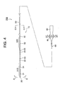
- FIG. 4 is a plan view showing the defibrillation catheter 200 of this embodiment
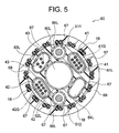
- FIG. 5 is a cross-sectional view of the distal region of the defibrillation catheter 100 (CC cross-sectional view of FIG. 4).
- the defibrillation catheter 200 of this embodiment is attached to the multi-lumen tube 60 having a distal flexible portion, a control handle 80 connected to the proximal end of the multi-lumen tube 60, and the distal flexible portion of the multi-lumen tube 60.
- the first DC electrode group 31G composed of the eight ring-shaped electrodes 31 and the eight ring-shaped members that are spaced from the first DC electrode group 31G toward the proximal end and are attached to the distal flexible portion of the multi-lumen tube 60
- a second DC electrode group 32G composed of electrodes 32, and four ring electrodes 33 for potential measurement mounted on the flexible end of the multi-lumen tube 60 between the first DC electrode group 31G and the second DC electrode group 32G;
- the tip tip 35 attached to the tip of the multi-lumen tube 60 and each of the electrodes 31 constituting the first DC electrode group 31G are connected.
- a first lead wire 43 connected to each of the first lead wire 33 and a distal end flexible portion of the multi-lumen tube 60 can be bent in a first direction (indicated by an arrow A in FIG. 4).
- the multi-lumen tube 60 constituting the defibrillation catheter 200 of this embodiment includes an inner part 68 made of resin, an outer part 69 made of resin covering the inner part 68, and a multi-lumen.
- the blade tube includes a resin braid 18 embedded in the outer portion 69 over the entire length of the tube 60.
- a central lumen 60L as a guide wire lumen and six sub-lumens 61L to 66L around the central lumen 60L are partitioned by a resin tube 67, respectively. Is formed.
- the first sub-lumen 61L and the second sub-lumen 62L are arranged to face each other with the central lumen 60L interposed therebetween. Further, the third sub-lumen 63L and the fourth sub-lumen 64L are arranged so as to face each other with the central lumen 60L interposed therebetween. The fifth sub-lumen 65L and the sixth sub-lumen 66L are arranged so as to face each other with the central lumen 60L interposed therebetween.
- the cross sections of the first sub-lumen 61L, the second sub-bloom 62L, the third sub-lumen 63L, and the fourth sub-lumen 64L are each a capsule shape (oval shape).
- the cross sections of the fifth sub-lumen 65L and the sixth sub-lumen 66L are each circular.
- the multi-lumen tube 60 is reinforced by a braid 18 made of resin over the entire length thereof, like the multi-lumen tube 10 constituting the defibrillation catheter 100 according to the first embodiment.
- the first lead wire group 41G shown in FIG. 5 is an aggregate of eight lead wires 41 connected to each of the eight electrodes 31 constituting the first DC electrode group 31G. With the first lead wire group 41G (lead wire 41), each of the eight electrodes 31 constituting the first DC electrode group 31G can be electrically connected to the DC power supply device.
- the eight electrodes 31 constituting the first DC electrode group 31G are connected to different lead wires 41, respectively.
- Each of the lead wires 41 is welded to the inner peripheral surface of the electrode 31 at the tip portion thereof, and enters the first sublumen 61L from a side hole formed in the tube wall of the multi-lumen tube 60.
- the eight lead wires 41 that have entered the first sub-lumen 61L extend to the first sub-bloom 61L as a first lead wire group 41G.
- the second lead wire group 42G shown in FIG. 5 is an aggregate of eight lead wires 42 connected to each of the eight electrodes 32 constituting the second DC electrode group 32G.
- Each of the eight electrodes 32 constituting the second DC electrode group 32G can be electrically connected to the DC power supply device by the second lead wire group 42G (lead wire 42).
- the eight electrodes 32 constituting the second DC electrode group 32G are connected to different lead wires 42, respectively.
- Each of the lead wires 42 is welded to the inner peripheral surface of the electrode 32 at the tip portion thereof, and enters the second sublumen 62L from a side hole formed in the tube wall of the multi-lumen tube 60.
- the eight lead wires 42 that have entered the second sub-lumen 62L extend to the second sub-lumen 62L as a second lead wire group 42G.
- the first lead wire group 41G (eight lead wires 41) extends to the first sub-lumen 61L
- the second lead wire group 42G (eight lead wires 42) becomes the second sub-bloom 62L.
- the first sub-lumen 61L from which the first lead wire group 41G extends and the second sub-lumen 62L from which the second lead wire group 42G extends sandwich the central lumen 60L. By arranging them so as to face each other, a sufficient separation distance between the first lead wire group 41G and the second lead wire group 42G can be secured.
- the four lead wires 43 shown in FIG. 5 are connected to each of the electrodes 33 for potential measurement.
- Each of the electrodes 33 can be connected to an electrocardiograph by a lead wire 43.
- the four electrodes 33 used for the saddle potential measurement are connected to different lead wires 43, respectively.
- Each of the lead wires 43 is welded to the inner peripheral surface of the electrode 33 at the tip portion thereof, and enters the third sub-lumen 63L from the side hole formed in the tube wall of the multi-lumen tube 60, so that the third sub Extends to lumen 63L.
- the defibrillation catheter 200 of the present embodiment includes a first operation wire 511 for bending the distal flexible portion of the multi-lumen tube 60 in the first direction (the direction indicated by arrow A), and the distal flexible portion. And a second operation wire 512 for bending in the second direction (the direction indicated by the arrow B).
- the “tip flexible portion” refers to the tip region of the multi-lumen tube that can be bent by pulling the operation wire (the first operation wire 511 and the second operation wire 512).
- the first operation wire 511 is inserted through the fifth sub-lumen 65L of the multi-lumen tube 60 so as to be movable in the tube axis direction.
- the distal end portion of the first operation wire 511 is connected and fixed to the distal tip 35 by, for example, solder filled in the inner space of the distal tip 35. Further, the proximal end of the first operation wire 511 is connected to a knob 85 of the control handle 80 and can be pulled.
- the second operation wire 512 is inserted in the sixth sub-lumen 66L of the multi-lumen tube 60 so as to be movable in the tube axis direction.
- the distal end portion of the second operation wire 512 is connected and fixed to the distal tip 35 by, for example, solder filled in the inner space of the distal tip 35.
- the proximal end of the second operation wire 512 is connected to a knob 85 of the control handle 80 and can be pulled.
- the first operation wire 511 is pulled and moved to the proximal end side of the fifth sub-lumen 65L, and the distal end flexible portion is moved in the first direction. It can be bent in the direction indicated by arrow A.
- the second operation wire 512 is pulled and moved to the proximal end side of the sixth sub-lumen 66L, and the distal end flexible portion is moved to the first end. It can be bent in two directions (directions indicated by arrows B).
- the lead wire is not inserted into the fourth sub-lumen 64L of the multi-lumen tube 60, and is a free lumen.
- the first lead wire group 41G and the second lead wire group 42G are sufficiently separated from each other in the multi-lumen tube 60 by being arranged so as to face each other with the central lumen 60L interposed therebetween. Can be completely insulated and isolated.
- the first lead wire group 41G (first DC electrode group 31G) and the second lead wire group 42G (second DC electrode group 32G) are applied.
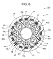
- FIG. 6 is a cross-sectional view showing the distal region of the defibrillation catheter 300 of this embodiment.
- the external shape of the defibrillation catheter 300 is the same as that of the defibrillation catheter 100 according to the first embodiment shown in FIGS. 1 and 2, and the illustration thereof is omitted, but the cross section shown in FIG. These are transverse cross sections at the same position as the BB cross sectional view of FIG.
- the defibrillation catheter 300 of the present embodiment is a first DC electrode group comprising a multi-lumen tube 70, a handle connected to the proximal end thereof, and eight ring-shaped electrodes attached to the distal end region of the multi-lumen tube 70.
- a second DC electrode group consisting of eight ring-shaped electrodes mounted on the distal end region of the multi-lumen tube 70 and spaced from the first DC electrode group to the proximal end side, and between the first DC electrode group and the second DC electrode group are connected to each of four ring-shaped electrodes for potential measurement attached to the tip region of the multi-lumen tube 70, a tip attached to the tip of the multi-lumen tube 70, and an electrode constituting the first DC electrode group.
- a first lead wire group 41G composed of the lead wires 41 and a second lead composed of lead wires 42 connected to each of the electrodes constituting the second DC electrode group.
- a wire group 42G and a lead wire 43 connected to each of the ring electrodes for potential measurement are provided, and voltages having different polarities are applied between the first DC electrode group and the second DC electrode group.
- the multi-lumen tube 70 constituting the defibrillation catheter 300 of this embodiment includes an inner part 701 made of resin, an outer part 702 made of resin covering the inner part 701, and a multi-lumen tube.
- the blade tube includes a resin braid 18 embedded in the outer portion 702 over the entire length of 70.
- the multi-lumen tube 70 (inner portion 701) is formed by dividing a central lumen 70L as a guide wire lumen and eight sub-lumens 71L to 78L around the central lumen 70L by resin tubes, respectively. Has been.
- the cross-sections of the eight sub-lumens 71L to 78L are each circular with a smaller diameter than the central lumen 70L.
- the multi-lumen tube 70 is reinforced by the resin braid 18 over the entire length thereof, similarly to the multi-lumen tube 10 constituting the defibrillation catheter 100 according to the first embodiment.
- the first sub-lumen 71L and the fifth sub-lumen 75L are arranged to face each other with the central lumen 70L interposed therebetween.
- Three lead wires 41 constituting the first lead wire group 41G extend to the first sub-lumen 71L, and three lead wires constituting the second lead wire group 42G to the fifth sub-lumen 75L. 42 extends.
- the second sub-lumen 72L and the sixth sub-lumen 76L are arranged to face each other with the central lumen 70L interposed therebetween.
- Three lead wires 41 constituting the first lead wire group 41G extend to the second sub-lumen 72L, and three lead wires constituting the second lead wire group 42G are extended to the sixth sub-lumen 76L. 42 extends.
- the third sub-lumen 73L and the seventh sub-bloom 77L are arranged to face each other with the central lumen 70L interposed therebetween.
- Two lead wires 41 constituting the first lead wire group 41G extend to the third sub-lumen 73L, and two lead wires constituting the second lead wire group 42G are extended to the seventh sub-lumen 77L. 42 extends.
- the fourth sub-lumen 74L and the eighth sub-lumen 78L are the central lumen 70L. It is arrange
- Four lead wires 43 connected to each of the ring electrodes for potential measurement extend in the fourth sublumen 74L, and an operation wire 51 extends in the eighth sublumen 78L.
- the eight lead wires 41 constituting the first lead wire group 41G are divided and extended into sub-lumens 71L to 73L to constitute the second lead wire group 42G.
- the eight lead wires 42 are divided and extended into sub-lumens 75L to 77L that face each of the sub-lumens 71L to 73L, and the first sub-lumen 71L from which the lead wire 41 extends and the lead wires 42 extend.
- an eighth sub-lumen 78L in which the operation wire 51 extends is formed, and the third sub-lumen 73L in which the lead wire 41 extends and the lead wire 42 extend.
- a fourth sub-lumen 74L in which the lead wire 43 extends is formed between the fifth sub-lumen 75L, and the lead wire 41 and the lead wire 42 are adjacent to each other in the circumferential direction. Since the lead wire 41 constituting the first lead wire group 41G and the lead wire 42 constituting the second lead wire group 42G are sufficiently separated from each other, the multi-lumen tube It is possible to completely isolate and isolate within 70. As a result, when a voltage necessary for defibrillation in the heart chamber is applied, a short circuit occurs between the first lead wire group 41G (first DC electrode group) and the second lead wire group 42G (second DC electrode group). Can be reliably prevented from occurring.
- the third sub-lumen 73L and the seventh sub-lumen 77L are vacant. It may be a lumen.
- the braid that reinforces the distal end region of the multi-lumen tube to which the electrode is attached is made of resin (similar to the braid 18), and the braid that reinforces the proximal end region of the multi-lumen tube to which the electrode is not attached is stainless steel or the like It may be made of metal.
Landscapes
- Health & Medical Sciences (AREA)
- Heart & Thoracic Surgery (AREA)
- Life Sciences & Earth Sciences (AREA)
- Cardiology (AREA)
- Animal Behavior & Ethology (AREA)
- Veterinary Medicine (AREA)
- Public Health (AREA)
- Biomedical Technology (AREA)
- Engineering & Computer Science (AREA)
- General Health & Medical Sciences (AREA)
- Radiology & Medical Imaging (AREA)
- Nuclear Medicine, Radiotherapy & Molecular Imaging (AREA)
- Vascular Medicine (AREA)
- Biophysics (AREA)
- Pulmonology (AREA)
- Anesthesiology (AREA)
- Hematology (AREA)
- Electrotherapy Devices (AREA)
Abstract
Priority Applications (5)
| Application Number | Priority Date | Filing Date | Title |
|---|---|---|---|
| CA3013423A CA3013423A1 (fr) | 2016-02-29 | 2016-12-16 | Catheter de defibrillation intracardiaque |
| CN201680082692.6A CN108697901A (zh) | 2016-02-29 | 2016-12-16 | 心腔内除颤导管 |
| KR1020187024197A KR102140881B1 (ko) | 2016-02-29 | 2016-12-16 | 심강 내 제세동 카테터 |
| EP16892738.2A EP3424557A4 (fr) | 2016-02-29 | 2016-12-16 | Cathéter de défibrillation intracardiaque |
| US16/109,587 US20190001143A1 (en) | 2016-02-29 | 2018-08-22 | Intracardiac defibrillation catheter |
Applications Claiming Priority (2)
| Application Number | Priority Date | Filing Date | Title |
|---|---|---|---|
| JP2016038472A JP6570123B2 (ja) | 2016-02-29 | 2016-02-29 | 心腔内除細動カテーテル |
| JP2016-038472 | 2016-02-29 |
Related Child Applications (1)
| Application Number | Title | Priority Date | Filing Date |
|---|---|---|---|
| US16/109,587 Continuation US20190001143A1 (en) | 2016-02-29 | 2018-08-22 | Intracardiac defibrillation catheter |
Publications (1)
| Publication Number | Publication Date |
|---|---|
| WO2017149904A1 true WO2017149904A1 (fr) | 2017-09-08 |
Family
ID=59743699
Family Applications (1)
| Application Number | Title | Priority Date | Filing Date |
|---|---|---|---|
| PCT/JP2016/087524 Ceased WO2017149904A1 (fr) | 2016-02-29 | 2016-12-16 | Cathéter de défibrillation intracardiaque |
Country Status (8)
| Country | Link |
|---|---|
| US (1) | US20190001143A1 (fr) |
| EP (1) | EP3424557A4 (fr) |
| JP (1) | JP6570123B2 (fr) |
| KR (1) | KR102140881B1 (fr) |
| CN (1) | CN108697901A (fr) |
| CA (1) | CA3013423A1 (fr) |
| TW (1) | TWI627981B (fr) |
| WO (1) | WO2017149904A1 (fr) |
Cited By (3)
| Publication number | Priority date | Publication date | Assignee | Title |
|---|---|---|---|---|
| CN111670062A (zh) * | 2018-02-07 | 2020-09-15 | 株式会社钟化 | 除颤导管系统、除颤用电源装置以及除颤用电源装置的控制方法 |
| JP2022514201A (ja) * | 2018-12-06 | 2022-02-10 | メドトロニック,インコーポレイテッド | 可動導体を有する埋め込み可能な医療用リード線 |
| JP7263593B1 (ja) | 2022-05-06 | 2023-04-24 | 学 朝妻 | 心腔内除細動システム |
Families Citing this family (8)
| Publication number | Priority date | Publication date | Assignee | Title |
|---|---|---|---|---|
| JP7261183B2 (ja) | 2018-02-06 | 2023-04-19 | 株式会社カネカ | カテーテルおよびその製造方法 |
| JP6881870B2 (ja) * | 2018-03-06 | 2021-06-02 | 日本ライフライン株式会社 | 心腔内除細動カテーテル |
| WO2020105768A1 (fr) * | 2018-11-23 | 2020-05-28 | 주식회사 타우피엔유메디칼 | Dispositif pour chirurgie de régurgitation valvulaire et fixation de dérivation de stimulateur cardiaque |
| KR20210100156A (ko) * | 2018-12-27 | 2021-08-13 | 니혼라이프라인 가부시키가이샤 | 심강 내 제세동 카테터 시스템 |
| JPWO2020188823A1 (ja) * | 2019-03-20 | 2021-04-01 | 日本ライフライン株式会社 | カテーテル |
| US12186010B2 (en) * | 2019-09-26 | 2025-01-07 | Biosense Webster (Israel) Ltd. | Wiring for multi-electrode catheter |
| US12171484B2 (en) * | 2020-05-27 | 2024-12-24 | Medtronic, Inc. | Safety default return path for electric field therapy |
| WO2023086215A2 (fr) * | 2021-11-10 | 2023-05-19 | St. Jude Medical, Cardiology Division, Inc. | Cathéter à lumières multiples contenant une entretoise intégrale et son procédé de fabrication |
Citations (7)
| Publication number | Priority date | Publication date | Assignee | Title |
|---|---|---|---|---|
| US4608986A (en) * | 1984-10-01 | 1986-09-02 | Cordis Corporation | Pacing lead with straight wire conductors |
| US5697965A (en) * | 1996-04-01 | 1997-12-16 | Procath Corporation | Method of making an atrial defibrillation catheter |
| US5755761A (en) * | 1996-04-26 | 1998-05-26 | Pharmatarget, Inc. | Atrial pacing catheter and method having multiple electrodes in the right atrium and coronary sinus |
| JP2010063708A (ja) | 2008-09-11 | 2010-03-25 | Japan Lifeline Co Ltd | 除細動カテーテル |
| JP2012050673A (ja) | 2010-09-01 | 2012-03-15 | Japan Lifeline Co Ltd | 心腔内除細動カテーテル |
| JP2012192124A (ja) | 2011-03-18 | 2012-10-11 | Japan Lifeline Co Ltd | 心腔内除細動カテーテル |
| JP2015029517A (ja) * | 2013-07-31 | 2015-02-16 | ニプロ株式会社 | 医療用チューブとそれを用いた経鼻カテーテル |
Family Cites Families (18)
| Publication number | Priority date | Publication date | Assignee | Title |
|---|---|---|---|---|
| US575761A (en) * | 1897-01-26 | Henry w | ||
| US5265623A (en) * | 1992-07-16 | 1993-11-30 | Angeion Corporation | Optimized field defibrillation catheter |
| US7130700B2 (en) * | 2002-11-19 | 2006-10-31 | Medtronic, Inc. | Multilumen body for an implantable medical device |
| US7496394B2 (en) * | 2004-11-15 | 2009-02-24 | Biosense Webster, Inc. | Internal reference coronary sinus catheter |
| US8818504B2 (en) * | 2004-12-16 | 2014-08-26 | Cardiac Pacemakers Inc | Leadless cardiac stimulation device employing distributed logic |
| JP4362536B2 (ja) * | 2008-04-11 | 2009-11-11 | 日本ライフライン株式会社 | カテーテル |
| CN102223912B (zh) * | 2008-12-12 | 2014-02-12 | 日本来富恩株式会社 | 心腔内除颤导管 |
| US20110270229A1 (en) * | 2008-12-26 | 2011-11-03 | Sumitomo Bakelite Co., Ltd. | Catheter |
| US9833616B2 (en) * | 2009-01-02 | 2017-12-05 | Medtronic, Inc. | System and method for cardiac lead |
| JP4545216B1 (ja) * | 2009-03-23 | 2010-09-15 | 日本ライフライン株式会社 | 心腔内除細動カテーテルシステム |
| US9468754B2 (en) * | 2009-05-29 | 2016-10-18 | Medtronic, Inc. | Leads for selective sensing and virtual electrodes |
| EP2457612B1 (fr) * | 2010-11-29 | 2013-01-23 | Sorin CRM SAS | Ensemble de stimulation/défibrillation du ventricule gauche par voie endocavitaire ou depuis une veine du réseau coronarien |
| KR101830466B1 (ko) * | 2010-12-24 | 2018-02-20 | 니혼라이프라인 가부시키가이샤 | 전극 카테터 |
| US8688232B2 (en) * | 2011-06-21 | 2014-04-01 | Greatbatch Ltd. | Multi-durometer reinforced suture sleeve |
| JP5875175B2 (ja) * | 2011-10-21 | 2016-03-02 | 日本ライフライン株式会社 | 電極カテーテル |
| EP2938397B1 (fr) * | 2012-12-31 | 2018-10-24 | Shanghai MicroPort Medical (Group) Co., Ltd. | Sonde cardiaque électrique |
| JP6201367B2 (ja) * | 2013-03-27 | 2017-09-27 | 住友ベークライト株式会社 | 医療用機器および医療用機器の製造方法 |
| US9486624B2 (en) * | 2013-06-13 | 2016-11-08 | Lambda Nu Technology Llc | Detection of implantable lead failures by differential EGM analysis |
-
2016
- 2016-02-29 JP JP2016038472A patent/JP6570123B2/ja active Active
- 2016-12-16 EP EP16892738.2A patent/EP3424557A4/fr not_active Withdrawn
- 2016-12-16 WO PCT/JP2016/087524 patent/WO2017149904A1/fr not_active Ceased
- 2016-12-16 CN CN201680082692.6A patent/CN108697901A/zh active Pending
- 2016-12-16 CA CA3013423A patent/CA3013423A1/fr not_active Abandoned
- 2016-12-16 KR KR1020187024197A patent/KR102140881B1/ko not_active Expired - Fee Related
-
2017
- 2017-01-10 TW TW106100724A patent/TWI627981B/zh not_active IP Right Cessation
-
2018
- 2018-08-22 US US16/109,587 patent/US20190001143A1/en not_active Abandoned
Patent Citations (7)
| Publication number | Priority date | Publication date | Assignee | Title |
|---|---|---|---|---|
| US4608986A (en) * | 1984-10-01 | 1986-09-02 | Cordis Corporation | Pacing lead with straight wire conductors |
| US5697965A (en) * | 1996-04-01 | 1997-12-16 | Procath Corporation | Method of making an atrial defibrillation catheter |
| US5755761A (en) * | 1996-04-26 | 1998-05-26 | Pharmatarget, Inc. | Atrial pacing catheter and method having multiple electrodes in the right atrium and coronary sinus |
| JP2010063708A (ja) | 2008-09-11 | 2010-03-25 | Japan Lifeline Co Ltd | 除細動カテーテル |
| JP2012050673A (ja) | 2010-09-01 | 2012-03-15 | Japan Lifeline Co Ltd | 心腔内除細動カテーテル |
| JP2012192124A (ja) | 2011-03-18 | 2012-10-11 | Japan Lifeline Co Ltd | 心腔内除細動カテーテル |
| JP2015029517A (ja) * | 2013-07-31 | 2015-02-16 | ニプロ株式会社 | 医療用チューブとそれを用いた経鼻カテーテル |
Non-Patent Citations (1)
| Title |
|---|
| See also references of EP3424557A4 |
Cited By (11)
| Publication number | Priority date | Publication date | Assignee | Title |
|---|---|---|---|---|
| CN111670062A (zh) * | 2018-02-07 | 2020-09-15 | 株式会社钟化 | 除颤导管系统、除颤用电源装置以及除颤用电源装置的控制方法 |
| CN111670062B (zh) * | 2018-02-07 | 2023-09-12 | 株式会社钟化 | 除颤导管系统、除颤用电源装置以及除颤用电源装置的控制方法 |
| JP2022514201A (ja) * | 2018-12-06 | 2022-02-10 | メドトロニック,インコーポレイテッド | 可動導体を有する埋め込み可能な医療用リード線 |
| JP7471294B2 (ja) | 2018-12-06 | 2024-04-19 | メドトロニック,インコーポレイテッド | 可動導体を有する埋め込み可能な医療用リード線 |
| JP7263593B1 (ja) | 2022-05-06 | 2023-04-24 | 学 朝妻 | 心腔内除細動システム |
| WO2023214529A1 (fr) * | 2022-05-06 | 2023-11-09 | 学 朝妻 | Système de défibrillation intracardiaque |
| JP2023165616A (ja) * | 2022-05-06 | 2023-11-16 | 学 朝妻 | 心腔内除細動システム |
| JP2023165531A (ja) * | 2022-05-06 | 2023-11-16 | 学 朝妻 | 心腔内除細動システム |
| JP2024052698A (ja) * | 2022-05-06 | 2024-04-11 | 学 朝妻 | 心腔内除細動システム |
| JP7482283B2 (ja) | 2022-05-06 | 2024-05-13 | 学 朝妻 | 心腔内除細動システム |
| JP7886361B2 (ja) | 2022-05-06 | 2026-07-07 | 学 朝妻 | 心腔内除細動システム |
Also Published As
| Publication number | Publication date |
|---|---|
| JP6570123B2 (ja) | 2019-09-04 |
| CA3013423A1 (fr) | 2017-09-08 |
| EP3424557A1 (fr) | 2019-01-09 |
| CN108697901A (zh) | 2018-10-23 |
| JP2017153633A (ja) | 2017-09-07 |
| US20190001143A1 (en) | 2019-01-03 |
| TW201737961A (zh) | 2017-11-01 |
| TWI627981B (zh) | 2018-07-01 |
| KR102140881B1 (ko) | 2020-08-03 |
| EP3424557A4 (fr) | 2019-04-03 |
| KR20180104094A (ko) | 2018-09-19 |
Similar Documents
| Publication | Publication Date | Title |
|---|---|---|
| JP6570123B2 (ja) | 心腔内除細動カテーテル | |
| JP4545210B2 (ja) | 除細動カテーテル | |
| WO2011121931A2 (fr) | Cathéter | |
| JP2010220778A (ja) | 心腔内除細動カテーテルシステム | |
| CN102223912B (zh) | 心腔内除颤导管 | |
| JP4937391B2 (ja) | 心腔内除細動カテーテル | |
| JP6876091B2 (ja) | 心腔内除細動カテーテル | |
| WO2020188823A1 (fr) | Cathéter | |
| JP2012192124A (ja) | 心腔内除細動カテーテル | |
| JP6628755B2 (ja) | 心腔内除細動カテーテル | |
| US20210402195A1 (en) | Intracardiac defibrillation catheter | |
| JP4346110B1 (ja) | 除細動カテーテル | |
| JP4346109B1 (ja) | 除細動カテーテル | |
| JP6691347B2 (ja) | 心腔内除細動カテーテル | |
| JP6881870B2 (ja) | 心腔内除細動カテーテル | |
| JP6864965B2 (ja) | 先端偏向操作可能カテーテル | |
| WO2025205928A1 (fr) | Dispositif de cathéter à électrodes | |
| JP5432932B2 (ja) | 電極カテーテル |
Legal Events
| Date | Code | Title | Description |
|---|---|---|---|
| WWE | Wipo information: entry into national phase |
Ref document number: 3013423 Country of ref document: CA |
|
| ENP | Entry into the national phase |
Ref document number: 20187024197 Country of ref document: KR Kind code of ref document: A |
|
| WWE | Wipo information: entry into national phase |
Ref document number: 1020187024197 Country of ref document: KR |
|
| NENP | Non-entry into the national phase |
Ref country code: DE |
|
| WWE | Wipo information: entry into national phase |
Ref document number: 2016892738 Country of ref document: EP |
|
| ENP | Entry into the national phase |
Ref document number: 2016892738 Country of ref document: EP Effective date: 20181001 |
|
| 121 | Ep: the epo has been informed by wipo that ep was designated in this application |
Ref document number: 16892738 Country of ref document: EP Kind code of ref document: A1 |