WO2017154100A1 - Procédé d'élimination de matériau organique et procédé de production de matériau recyclé - Google Patents
Procédé d'élimination de matériau organique et procédé de production de matériau recyclé Download PDFInfo
- Publication number
- WO2017154100A1 WO2017154100A1 PCT/JP2016/057157 JP2016057157W WO2017154100A1 WO 2017154100 A1 WO2017154100 A1 WO 2017154100A1 JP 2016057157 W JP2016057157 W JP 2016057157W WO 2017154100 A1 WO2017154100 A1 WO 2017154100A1
- Authority
- WO
- WIPO (PCT)
- Prior art keywords
- organic material
- composite material
- processing liquid
- treatment liquid
- organic
- Prior art date
- Legal status (The legal status is an assumption and is not a legal conclusion. Google has not performed a legal analysis and makes no representation as to the accuracy of the status listed.)
- Ceased
Links
Images


Classifications
-
- C—CHEMISTRY; METALLURGY
- C08—ORGANIC MACROMOLECULAR COMPOUNDS; THEIR PREPARATION OR CHEMICAL WORKING-UP; COMPOSITIONS BASED THEREON
- C08J—WORKING-UP; GENERAL PROCESSES OF COMPOUNDING; AFTER-TREATMENT NOT COVERED BY SUBCLASSES C08B, C08C, C08F, C08G or C08H
- C08J11/00—Recovery or working-up of waste materials
- C08J11/04—Recovery or working-up of waste materials of polymers
- C08J11/10—Recovery or working-up of waste materials of polymers by chemically breaking down the molecular chains of polymers or breaking of crosslinks, e.g. devulcanisation
- C08J11/18—Recovery or working-up of waste materials of polymers by chemically breaking down the molecular chains of polymers or breaking of crosslinks, e.g. devulcanisation by treatment with organic material
-
- B—PERFORMING OPERATIONS; TRANSPORTING
- B09—DISPOSAL OF SOLID WASTE; RECLAMATION OF CONTAMINATED SOIL
- B09B—DISPOSAL OF SOLID WASTE NOT OTHERWISE PROVIDED FOR
- B09B3/00—Destroying solid waste or transforming solid waste into something useful or harmless
- B09B3/40—Destroying solid waste or transforming solid waste into something useful or harmless involving thermal treatment, e.g. evaporation
-
- B—PERFORMING OPERATIONS; TRANSPORTING
- B01—PHYSICAL OR CHEMICAL PROCESSES OR APPARATUS IN GENERAL
- B01J—CHEMICAL OR PHYSICAL PROCESSES, e.g. CATALYSIS OR COLLOID CHEMISTRY; THEIR RELEVANT APPARATUS
- B01J19/00—Chemical, physical or physico-chemical processes in general; Their relevant apparatus
- B01J19/0006—Controlling or regulating processes
- B01J19/0013—Controlling the temperature of the process
-
- B—PERFORMING OPERATIONS; TRANSPORTING
- B09—DISPOSAL OF SOLID WASTE; RECLAMATION OF CONTAMINATED SOIL
- B09B—DISPOSAL OF SOLID WASTE NOT OTHERWISE PROVIDED FOR
- B09B3/00—Destroying solid waste or transforming solid waste into something useful or harmless
- B09B3/70—Chemical treatment, e.g. pH adjustment or oxidation
-
- C—CHEMISTRY; METALLURGY
- C08—ORGANIC MACROMOLECULAR COMPOUNDS; THEIR PREPARATION OR CHEMICAL WORKING-UP; COMPOSITIONS BASED THEREON
- C08J—WORKING-UP; GENERAL PROCESSES OF COMPOUNDING; AFTER-TREATMENT NOT COVERED BY SUBCLASSES C08B, C08C, C08F, C08G or C08H
- C08J11/00—Recovery or working-up of waste materials
- C08J11/04—Recovery or working-up of waste materials of polymers
- C08J11/10—Recovery or working-up of waste materials of polymers by chemically breaking down the molecular chains of polymers or breaking of crosslinks, e.g. devulcanisation
- C08J11/16—Recovery or working-up of waste materials of polymers by chemically breaking down the molecular chains of polymers or breaking of crosslinks, e.g. devulcanisation by treatment with inorganic material
-
- B—PERFORMING OPERATIONS; TRANSPORTING
- B01—PHYSICAL OR CHEMICAL PROCESSES OR APPARATUS IN GENERAL
- B01J—CHEMICAL OR PHYSICAL PROCESSES, e.g. CATALYSIS OR COLLOID CHEMISTRY; THEIR RELEVANT APPARATUS
- B01J2208/00—Processes carried out in the presence of solid particles; Reactors therefor
- B01J2208/00008—Controlling the process
- B01J2208/00548—Flow
- B01J2208/00557—Flow controlling the residence time inside the reactor vessel
-
- B—PERFORMING OPERATIONS; TRANSPORTING
- B01—PHYSICAL OR CHEMICAL PROCESSES OR APPARATUS IN GENERAL
- B01J—CHEMICAL OR PHYSICAL PROCESSES, e.g. CATALYSIS OR COLLOID CHEMISTRY; THEIR RELEVANT APPARATUS
- B01J2219/00—Chemical, physical or physico-chemical processes in general; Their relevant apparatus
- B01J2219/00049—Controlling or regulating processes
- B01J2219/00051—Controlling the temperature
-
- B—PERFORMING OPERATIONS; TRANSPORTING
- B01—PHYSICAL OR CHEMICAL PROCESSES OR APPARATUS IN GENERAL
- B01J—CHEMICAL OR PHYSICAL PROCESSES, e.g. CATALYSIS OR COLLOID CHEMISTRY; THEIR RELEVANT APPARATUS
- B01J2219/00—Chemical, physical or physico-chemical processes in general; Their relevant apparatus
- B01J2219/00049—Controlling or regulating processes
- B01J2219/00164—Controlling or regulating processes controlling the flow
- B01J2219/00166—Controlling or regulating processes controlling the flow controlling the residence time inside the reactor vessel
-
- C—CHEMISTRY; METALLURGY
- C08—ORGANIC MACROMOLECULAR COMPOUNDS; THEIR PREPARATION OR CHEMICAL WORKING-UP; COMPOSITIONS BASED THEREON
- C08J—WORKING-UP; GENERAL PROCESSES OF COMPOUNDING; AFTER-TREATMENT NOT COVERED BY SUBCLASSES C08B, C08C, C08F, C08G or C08H
- C08J5/00—Manufacture of articles or shaped materials containing macromolecular substances
- C08J5/04—Reinforcing macromolecular compounds with loose or coherent fibrous material
- C08J5/0405—Reinforcing macromolecular compounds with loose or coherent fibrous material with inorganic fibres
- C08J5/042—Reinforcing macromolecular compounds with loose or coherent fibrous material with inorganic fibres with carbon fibres
-
- C—CHEMISTRY; METALLURGY
- C08—ORGANIC MACROMOLECULAR COMPOUNDS; THEIR PREPARATION OR CHEMICAL WORKING-UP; COMPOSITIONS BASED THEREON
- C08J—WORKING-UP; GENERAL PROCESSES OF COMPOUNDING; AFTER-TREATMENT NOT COVERED BY SUBCLASSES C08B, C08C, C08F, C08G or C08H
- C08J5/00—Manufacture of articles or shaped materials containing macromolecular substances
- C08J5/04—Reinforcing macromolecular compounds with loose or coherent fibrous material
- C08J5/0405—Reinforcing macromolecular compounds with loose or coherent fibrous material with inorganic fibres
- C08J5/043—Reinforcing macromolecular compounds with loose or coherent fibrous material with inorganic fibres with glass fibres
-
- Y—GENERAL TAGGING OF NEW TECHNOLOGICAL DEVELOPMENTS; GENERAL TAGGING OF CROSS-SECTIONAL TECHNOLOGIES SPANNING OVER SEVERAL SECTIONS OF THE IPC; TECHNICAL SUBJECTS COVERED BY FORMER USPC CROSS-REFERENCE ART COLLECTIONS [XRACs] AND DIGESTS
- Y02—TECHNOLOGIES OR APPLICATIONS FOR MITIGATION OR ADAPTATION AGAINST CLIMATE CHANGE
- Y02W—CLIMATE CHANGE MITIGATION TECHNOLOGIES RELATED TO WASTEWATER TREATMENT OR WASTE MANAGEMENT
- Y02W30/00—Technologies for solid waste management
- Y02W30/50—Reuse, recycling or recovery technologies
- Y02W30/62—Plastics recycling; Rubber recycling
Definitions
- the present invention relates to an organic material removing method and a recycled material manufacturing method.
- Composite materials obtained by combining organic materials such as resins and inorganic materials such as carbon fibers are used in various fields.
- Such composite materials include carbon fiber reinforced plastic (Carbon Fiber Reinforced Plastic, CFRP) containing resin and carbon fiber, glass fiber reinforced plastic (Glass Fiber Reinforced Plastic, GFRP) containing resin and glass fiber, resin and metal parts. And a prepreg for producing a CFRP, a GFRP, and the like.
- JP2013-82850A discloses a continuous dissolution treatment apparatus. Furthermore, JP2013-82850A discloses a batch-type dissolution treatment apparatus as a conventional example.
- the organic material removing method of the present embodiment is a method in which the heated processing liquid is brought into contact with a plate-like composite material containing an inorganic material and an organic material that is decomposed by the processing liquid while being circulated in a unidirectional flow.
- the composite material when the heated processing liquid is brought into contact with the plate-shaped composite material while being circulated in a unidirectional flow, the composite material is placed on at least a part of the plate surface of the composite material. Place them so that they touch. Therefore, the treatment liquid comes into efficient contact with the surface of the composite material.
- the composite material contains an organic material that is decomposed by the treatment liquid, and the decomposition of the organic material proceeds efficiently when the treatment liquid is efficiently brought into contact with the surface of the composite material. As a result, the organic material is efficiently removed from the composite material.
- the surface direction of the composite material may be arranged along the flow direction of the processing liquid.
- the method for producing a recycled material makes contact with a plate-like composite material containing an inorganic material and an organic material that is decomposed by the treatment liquid while circulating the heated treatment liquid in a unidirectional flow.
- Removing the organic material, and a separation step of separating the inorganic material as a recycled material from the treatment liquid containing the decomposition product of the organic material, and the composite material in the removal step includes the step of It arrange
- the composite material is processed on at least a part of the plate surface of the composite material. Arrange so that the liquid contacts. Therefore, the treatment liquid comes into efficient contact with the surface of the composite material.
- the composite material contains an organic material that is decomposed by the treatment liquid, and the decomposition of the organic material proceeds efficiently when the treatment liquid is efficiently brought into contact with the surface of the composite material.
- the composite material may be arranged along the flow direction of the processing liquid.
- an organic material removing method capable of efficiently removing an organic material from a composite material.
- recover efficiently an inorganic material as a regenerated material from a composite material can be provided.
- FIG. 4 is a view showing a front view of a container 12.
- FIG. 6 is a plan view of the container 12.
- 2 is a cross-sectional view of a bucket 30.
- FIG. 4 is a front view showing another example of the bucket 30.
- the window part 50 is opened toward the outer side of the side part 33, and the bucket 30 is disposed in a state where the part of the side part 33 of the bucket 30 that faces the position where the window part 50 is attached is grounded.
- FIG. It is a figure which shows the state by which the bucket 30 was arrange
- It is the schematic which shows the principal part of the organic material removal apparatus 2 which is another example of an organic material removal apparatus.
- the present invention is not limited to the following embodiments.
- the components including element steps and the like
- the present invention is not limited thereto.
- the term “process” includes a process that is independent of other processes and includes the process if the purpose of the process is achieved even if it cannot be clearly distinguished from the other processes. It is.
- numerical values indicated by using “to” include numerical values described before and after “to” as the minimum value and the maximum value, respectively.
- the upper limit value or the lower limit value described in one numerical range may be replaced with the upper limit value or the lower limit value of another numerical range.
- size of the member in each figure is notional, The relative relationship of the magnitude
- symbol is provided to the member which has the substantially same function through all the drawings, and the overlapping description may be abbreviate
- the organic material removing method of the present embodiment is a method in which the heated processing liquid is brought into contact with a plate-like composite material containing an inorganic material and an organic material that is decomposed by the processing liquid while being circulated in a unidirectional flow.
- the composite material applicable to the organic material removal method of the present embodiment includes an inorganic material and an organic material that is decomposed by the treatment liquid (hereinafter, may be referred to as “first organic material”).
- the composite material may further include an organic material that is not decomposed by the treatment liquid (hereinafter may be referred to as “second organic material”). Specific examples of the composite material include CFRP, GFRP, a mold coil, a motor coil, and a prepreg.
- the term “decomposes” of an organic material means that the molecular structure of the organic material changes due to the action of the treatment liquid, and the molecular weight becomes small enough to be taken into the treatment liquid. .
- the first organic material examples include a resin.
- the first organic material may be a thermosetting resin or a thermoplastic resin.
- the resin may be in a completely cured or solidified state or may not be completely cured or solidified.
- the type of the first organic material is not particularly limited, and conditions such as a component of the processing liquid, a processing temperature, and a processing time are selected depending on the type of the resin. From the viewpoint of ease of decomposition by the treatment liquid, a resin containing an ester bond is preferable.
- the resin containing an ester bond include a polyester resin (unsaturated polyester resin or saturated polyester resin), an epoxy resin containing an ester bond (an acid anhydride-cured epoxy resin, a glycidyl ester type epoxy resin, and the like).
- the first organic material contained in the composite material may be only one type or two or more types.
- Examples of the second organic material include thermoplastic resins and aramid fibers. Even if the second organic material is dispersed in the first organic material, mixed with the first organic material, formed as a member different from the first organic material, etc. It may be in the state.
- the type is not particularly limited.
- polyolefin resin, polyacrylic resin, and polyamide resin are mentioned.
- the second organic material contained in the composite material may be only one type or two or more types.
- the polyolefin resin include polypropylene and polyethylene.
- the polyacrylic resin include polymethyl methacrylate.
- the polyamide resin include nylon 6,6, nylon 6, nylon 11, nylon 12, and the like.
- the second organic material is an aramid fiber, the type is not particularly limited. Examples of the aramid fiber include para-aramid and meta-aramid.
- the softening point is not particularly limited. From the viewpoint of efficiently removing the second organic material from the composite material, for example, it may be 235 ° C. or lower, and preferably 150 ° C. or lower.
- the second organic material contains two or more thermoplastic resins having different softening points, the highest softening point is set as the softening point of the second organic material.
- the softening point of the resin refers to a value measured according to JIS K 7206: 1999.
- Examples of the inorganic material included in the composite material include carbon, glass, ceramics, metal, and semiconductor.
- the state of the inorganic material in the composite material is not particularly limited, and examples thereof include a fiber shape, a cloth shape, a particle shape, a layer shape, a plate shape, and a rod shape.
- the inorganic material contained in the composite material may be only one type or two or more types.
- the shape of the composite material is a plate shape.
- the plate-shaped composite material may be cut into a substantially square shape.
- the fiber length tends to be substantially uniform when the recovered inorganic material is a fiber material such as carbon fiber. Therefore, it is useful when the recovered fiber material is reused for producing a nonwoven fabric or the like.
- the composite material includes a fibrous inorganic material (eg, carbon fiber), the first organic material includes a resin containing an ester bond (eg, an epoxy resin), and the second organic material includes an ester.
- a thermoplastic resin containing no bond for example, a polyolefin resin is included.
- the treatment liquid used in the present embodiment can decompose the organic material contained in the composite material (the first organic material when the composite material includes the first organic material and the second organic material). If it is, it will not be restrict
- the organic material includes a resin containing an ester bond
- the treatment liquid that causes decomposition of the ester bond include a treatment liquid containing an organic solvent and a decomposition catalyst.
- the type of the organic solvent is not particularly limited.
- the organic solvent include alcohol solvents, ketone solvents, ether solvents, amide solvents, and the like.
- alcohol solvent examples include benzyl alcohol, methanol, ethanol, 1-propanol, 2-propanol, 1-butanol, 2-butanol, isobutanol, tert-butanol, 1-pentanol, 2-pentanol, 3-pentanol, 2-methyl-1-butanol, isopentyl alcohol, tert-pentyl alcohol, 3-methyl-2-butanol, neopentyl alcohol, 1-hexanol, 2-methyl-1-pentanol, 4-methyl-2-pentanol 2-ethyl-1-butanol, 1-heptanol, 2-heptanol, 3-heptanol, cyclohexanol, 1-methylcyclohexanol, 2-methylcyclohexanol, 3-methylcyclohexanol, 4-methylcyclohexanol, ethyl Lenglycol, ethylene glycol monomethyl ether, ethylene glycol
- ketone solvent examples include diisobutyl ketone, methylcyclohexanone, acetone, methyl ethyl ketone, 2-pentanone, 3-pentanone, 2-hexanone, methyl isobutyl ketone, 2-heptanone, 4-heptanone, cyclohexanone, phorone, and isophorone.
- ether solvents include dipropyl ether, dibenzyl ether, phenyl benzyl ether, diisopropyl ether, dibutyl ether, dihexyl ether, anisole, phenetole, dioxane, tetrahydrofuran, acetal, ethylene glycol dimethyl ether, diethylene glycol dimethyl ether, ethylene glycol diethyl ether, and the like. It is done.
- the amide solvent include N, N-dimethylformamide, N, N-dimethylacetamide and the like.
- alcohol solvents are preferable from the viewpoint of being hardly changed by heating and the like, benzyl alcohol, 1,4-butanediol and the like are more preferable, and benzyl alcohol is more preferable.
- the organic solvent contained in the treatment liquid may be only one type or two or more types.
- the boiling point of the treatment liquid is not particularly limited, and is selected according to the type of organic material contained in the composite material. That is, the boiling point of the treatment liquid is selected from a temperature equal to or higher than the temperature at which the organic material contained in the composite material is decomposed.
- the boiling point of the treatment liquid is equal to or higher than the temperature at which the first organic material decomposes, and the second organic material It is selected from temperatures that are above the softening point.
- examples of the decomposition catalyst include phosphates and metal hydroxides.
- examples of the phosphate include tripotassium phosphate, trirubium phosphate, trisodium phosphate, and trilithium phosphate.
- examples of the metal hydroxide include rubidium hydroxide, potassium hydroxide, sodium hydroxide, lithium hydroxide and the like.
- the decomposition catalyst contained in the treatment liquid may be only one type or two or more types.
- the concentration of the decomposition catalyst when the treatment liquid contains the decomposition catalyst is not particularly limited. For example, it may be in the range of 0.4% by mass to 20% by mass.
- the heated composite is brought into contact with the plate-shaped composite material.
- the flow direction of the treatment liquid with respect to the composite material is not particularly limited.
- the flow direction of the treatment liquid with respect to the composite material is a one-way flow, and the flow direction is not changed during the removal process.
- the treatment liquid is introduced from the treatment tank and the treatment tank into which the treatment liquid flows into the treatment tank.
- the processing liquid outflow portion to be outflowed is arranged separately.
- the temperature profile of the treatment liquid when decomposing and removing the organic material is not particularly limited, and the treatment liquid may be treated at a predetermined temperature for a predetermined time. Alternatively, the temperature of the treatment liquid may be set in at least two stages.
- the temperature and treatment time of the treatment liquid in each stage can be selected based on the type and degree of curing of the organic material and the shape of the composite material, There is no particular limitation.
- the temperature of the treatment liquid in the first stage can be in the range of 30 ° C. to 190 ° C.
- the treatment time in the first stage can be in the range of 1 minute to 180 minutes
- the second stage The temperature of the treatment liquid in can be in the range of 100 ° C. to 235 ° C.
- the treatment time in the second stage can be in the range of 1 minute to 720 minutes.
- a step of setting the temperature of the processing liquid to be equal to or higher than the softening point of the second organic material may be provided.
- the temperature of the processing liquid promotes the curing or solidification of the organic material. It is preferable that the first stage maintained at a difficult temperature and the second stage maintained at a temperature higher than the temperature condition of the first stage are included in this order.
- the temperature of the processing liquid is raised at a stroke, the organic material is removed by the processing liquid, but the heat of the processing liquid Since a curing reaction of the organic material may occur, the curing of the organic material may progress depending on the contact state between the treatment liquid and the composite material, and it may be difficult to remove the organic material.
- the heating conditions of the treatment liquid include the first stage and the second stage described above in this order, thereby suppressing the curing or the like of the organic material contained in the composite material that is not completely cured or solidified. The removal efficiency tends to improve.
- the composite material is disposed so that the treatment liquid contacts at least a part of the plate surface of the composite material. For this reason, the opposing surfaces of the plurality of plate-shaped composite materials are in contact with each other, so that the processing liquid does not tend to enter between the composite materials.
- the plurality of plate-shaped composite materials may be arranged so that the plate surface and the plate surface are not completely in contact with each other.
- “the plate surface and the plate surface are not in complete contact” means that the plate-like composite materials are in contact with each other and the treatment liquid cannot enter between the composite materials. Means not.
- the treatment liquid can be sufficiently brought into contact with the composite material.
- a mode in which the plane direction of the plate-shaped composite material is arranged so as to follow the flow direction of the processing liquid can be mentioned. If the plate-shaped composite material is in such a state, the plate-shaped composite material can supply abundant processing liquid to the surface of the widest area in the plate-shaped composite material without hindering the flow of the processing liquid. it can.
- the heated treatment liquid is brought into contact with a plate-like composite material containing an inorganic material and an organic material that is decomposed by the treatment liquid while being circulated in a unidirectional flow.
- the embodiment of the “removing step” in the method for producing a recycled material of the present embodiment can be the same as that of the organic material removing method of the present embodiment.
- an inorganic material is separated and recovered as a recycled material from a treatment liquid containing a decomposition product of an organic material.
- the separation method of the inorganic material is not particularly limited, and a conventionally known method can be selected in view of the amount, shape, etc. of the inorganic material.
- the recovered inorganic material is reused as a recycled material.
- FIG. 1 is a schematic view showing a main part of an organic material removing apparatus 1 which is an example of an organic material removing apparatus capable of performing the organic material removing method and the recycled material manufacturing method of the present embodiment.
- the composite material is arranged so that the surface direction of the plate-shaped composite material including the inorganic material and the organic material decomposed by the treatment liquid is along the vertical direction, and is along the surface direction of the plate-shaped composite material.
- the heated processing liquid flows that is, the heated processing liquid flows in a direction along the vertical direction
- the heated processing liquid flows from the lower side to the upper side in the vertical direction.
- the organic material removal apparatus 1 has a column 10 that is a processing tank.
- the column 10 includes a cylindrical column main body, a conical conical portion formed at one end on the lower side in the vertical direction of the column main body, and a lid (not shown) that can be opened and closed to close an opening at one end on the upper side in the vertical direction of the column main body.
- the column main body in the column 10 accommodates a container 12 that stores a composite material including an inorganic material and an organic material that is decomposed by the treatment liquid.
- a portion of the column 10 in which the container 12 is accommodated is the accommodating portion 14.
- a treatment liquid inflow portion 16 is provided at the apex portion of the conical portion of the column 10.
- the processing liquid inflow portion 16 is located on the lower side of the accommodating portion 14 in the vertical direction.
- a treatment liquid outflow portion 18 is provided above the storage portion 14 of the column 10 in the vertical direction.
- a baffle plate 22 which is one of rectifying means for rectifying the processing liquid 20 is provided at the boundary between the column main body and the conical portion.
- the organic material removing apparatus 1 includes a processing liquid circulation unit that allows the processing liquid 20 to flow into the column 10 from the processing liquid inflow portion 16 and causes the processing liquid 20 in the column 10 to flow out of the processing liquid outflow portion 18.
- the processing liquid circulation means includes a storage tank 24 that stores the processing liquid 20 that flows into the column 10, a pump P that flows the processing liquid 20 stored in the storage tank 24 into the column 10, and A plurality of pipes constituting the flow path of the treatment liquid 20 and a plurality of valves provided in the middle of the pipe to regulate the flow of the treatment liquid 20 are provided.
- the storage tank 24 also has a function of storing the processing liquid 20 that has flowed out of the column 10.
- the organic material removing apparatus 1 includes a temperature management unit that heats or cools the treatment liquid 20.
- the temperature management means includes a heating heat exchanger 26 and a cooling heat exchanger 28.
- the organic material removing apparatus 1 may have a moving means for accommodating the container 12 in the accommodating portion 14 of the column 10 and taking out the container 12 from the accommodating portion 14 as necessary.
- a chain block can be used as the moving means.
- the moving means may further include a frame, a guide rail, a sprocket, a chain, a drive shaft, a position sensor, and the like. The moving means moves the container 12 in the vertical direction and the horizontal direction in FIG. 1 as necessary.
- the shape of the container 12 for storing the composite material is not particularly limited, and can be appropriately selected depending on the shape of the treatment tank.
- the shape of the container 12 is preferably a rectangular parallelepiped.
- the shape of the container 12 is preferably cylindrical according to the shape of the column main body of the column 10.
- FIG. 2A and 2B are diagrams showing an example of the container 12, FIG. 2A shows a front view of the container 12, and FIG. 2B shows a plan view of the container 12, respectively.
- the container 12 shown in FIGS. 2A and 2B is configured by integrating three cylindrical buckets 30 connected in the height direction of the bucket 30.
- FIG. 3 is a cross-sectional view of the bucket 30.
- the bucket 30 includes a bottom portion 31 and a side surface portion 33 provided so as to rise from the outer peripheral portion of the bottom portion 31 in the thickness direction of the bottom portion 31.
- the direction in which the side surface portion 33 rises is the height direction of the bucket 30.
- the number of buckets is not limited to three.
- the shape is not limited to a cylindrical shape, and may be a rectangular parallelepiped or the like. As shown in FIGS.
- the three buckets 30 are integrated by a connecting member 36 having a connecting rod 32 that penetrates the three buckets 30 and a support plate 34 that supports the bottom 31 of the lowermost bucket 30.
- a handle 38 is attached to the upper side of the connecting member 36 via an attachment member 40, and the container 12 can be easily moved by hooking a hook of a chain block as an example of a moving means to the handle 38. It has been made possible.
- a plate-like lid 42 is disposed on the upper side of the uppermost bucket 30. A hole 44 is provided at the center of the lid 42 so that the flow of the processing liquid 20 is not hindered.
- the bucket 30 is configured by attaching a punching metal, an expanded metal, a wire mesh, or the like to a frame, and a plurality of holes are formed on the surface of the bucket 30 constituting the container 12 through the inside and the outside of the bucket 30. It has been. Therefore, the processing liquid 20 can easily pass through the bucket 30.
- the mesh size, the aperture ratio, and the like of the bucket 30 are appropriately set according to the shape, size, and the like of the composite material and the inorganic material.
- the lid 42 may be configured by a punching metal, an expanded metal, a wire mesh, or the like attached to the frame in addition to the plate-like member provided with the hole 44.
- a plurality of partition plates 46 which are one of dam members that arrange the surface direction of the plate-shaped composite material along the flow direction of the processing liquid 20, are provided inside the bucket 30. May be.
- the number of the partition plates 46 provided inside the bucket 30 is not particularly limited.
- the dam member may be a plate-like member such as the partition plate 46, may be a rod-like member extending from a predetermined position of the bottom 31 in the height direction of the bucket 30, or other shape member
- the composite member is not particularly limited as long as the composite member can be disposed along the flow direction of the treatment liquid 20.
- FIG. 4 is a front view showing another example of the bucket 30.
- a window 50 is attached to the side surface 33 of the bucket 30 in FIG.
- the window portion 50 can be opened and closed toward the outside of the side surface portion 33.
- FIG. 5A and 5B are diagrams for explaining a method of storing the plate-shaped composite material 52 in the bucket 30 having the window portion 50.
- FIG. 5A the window portion 50 is opened toward the outside of the side surface portion 33, and the bucket 30 is arranged in a state where the portion of the side surface portion 33 of the bucket 30 that faces the position where the window portion 50 is attached is grounded.
- FIG. 5B the bucket 30 is arranged with the window portion 50 closed and the bottom portion 31 of the bucket 30 grounded.
- 5A and 5B in order to explain the state of the plate-shaped composite material 52 in an easy-to-understand manner, a part of the side surface portion 33 of the bucket 30 is cut away.
- the window portion 50 of the bucket 30 is opened toward the outside of the side surface portion 33, and the portion of the side surface portion 33 of the bucket 30 that faces the position where the window portion 50 is attached is grounded.
- the plate-shaped composite material 52 is accommodated in the bucket 30 through the window 50. Since the portion of the side surface 33 of the bucket 30 that faces the position where the window 50 is attached is grounded, if the plate-shaped composite material 52 is stored in the bucket 30 through the window 50, the plate The surface direction of the composite material 52 is easily flattened in the direction along the height direction of the bucket 30.
- a plate-shaped composite material 52 can be disposed in the bucket 30 along the height direction of 30.
- the material of the column 10 is not particularly limited, and stainless steel (SUS303, SUS316, etc.), Hastelloy (Hastelloy B, Hastelloy B-2, Hastelloy C276, etc.) having excellent corrosion resistance against the heated treatment liquid 20 is used. Can be used.
- a column 10 having a cylindrical column main body and a conical conical portion formed at one end on the lower side in the vertical direction of the column main body is used as the processing tank.
- the shape of a processing tank is not limited to a cylindrical shape, A rectangular parallelepiped etc. may be sufficient.
- the ratio (distance / length) to the maximum length of the cross section is preferably 1 to 20, more preferably 2 to 10, and further preferably 3 to 5.
- the maximum length of the cross section of the treatment tank is as follows. When the cross section of the treatment tank is circular, the maximum length of the cross section of the treatment tank is the diameter of the circle. When the cross section of the processing tank is rectangular, the maximum length of the cross section of the processing tank is the length of the diagonal line of the rectangle. When the cross section of the treatment tank has another shape, the maximum length of the cross section of the treatment tank is the diameter of a circle circumscribing the cross section of the treatment tank.
- the shape of the baffle plate 22 provided at the boundary between the column main body and the conical portion in the column 10 is not particularly limited.
- the baffle plate 22 may be, for example, a disc-shaped plate that covers one end of the cylindrical column body on the lower side in the vertical direction and has a plurality of holes and is insoluble in the processing liquid 20.
- the area of the container 14 and the area occupied by the container 12 can be as small as possible when observed from the flow direction of the processing liquid 20 in the column 10. It is preferable that they match.
- the amount of the processing liquid 20 that flows out of the column 10 without passing through the container 12 can be reduced. Therefore, the amount of the processing liquid 20 that does not contribute to the processing of the composite material is reduced, and the organic material can be more efficiently removed from the composite material.
- the area occupied by the container 12 is preferably 80 or more when the area of the accommodating portion 14 is 100.
- the composite material accommodated in the container 12 is arranged without being biased when observed from the flow direction of the treatment liquid 20 in the column 10.
- the treatment liquid 20 comes into contact with the composite material efficiently, and the organic material can be efficiently removed from the composite material.
- the temperature management means included in the organic material removing apparatus 1 includes a heating heat exchanger 26 and a cooling heat exchanger 28.
- HM heat transfer oil
- CW cooling water
- the processing liquid 20 can be set to a desirable temperature condition.
- the heating means for the treatment liquid 20 in the temperature management means is not limited to the heating heat exchanger 26, and a heater, a microwave heater, a dielectric heater, or the like can be used.
- the cooling means of the treatment liquid 20 in the temperature management means is not limited to the cooling heat exchanger 28, and various cooling means of water cooling type and air cooling type can be used.
- the processing liquid circulation means included in the organic material removing apparatus 1 controls the circulation of the processing liquid 20 by starting and stopping the pump P and opening and closing a plurality of valves provided in the middle of the piping to regulate the flow of the processing liquid 20. .
- the starting and stopping of the pump P and the opening and closing of the valve are controlled by control means (not shown).
- the volume of the storage tank 24 is not particularly limited, and can be appropriately selected in consideration of the volume of the column 10.
- a lid (not shown) in the column 10 is opened, and a container 12 containing a plate-shaped composite material is accommodated in the accommodating portion 14 in the column 10 by a moving means (not shown), and then a lid (not shown) in the column 10.
- the body is closed.
- the plurality of plate-shaped composite materials are arranged in the container 12 so that the plate surface and the plate surface are not completely in contact with each other. Therefore, the treatment liquid 20 comes into contact with at least a part of the plate surface of the composite material.
- the processing liquid 20 is introduced into the storage tank 24 along the arrow R, and the processing liquid 20 is stored in the storage tank 24.
- the treatment liquid 20 may be an unused one, one that has been subjected to a regeneration process described below, or an unused one that has been subjected to a regeneration process.
- Valve A is opened and valves B, C and D are closed.
- the pump P is driven, and the processing liquid 20 stored in the storage tank 24 passes through the valve A and the heating heat exchanger 26 and flows into the column 10 from the processing liquid inflow portion 16.
- the excess processing liquid 20 flows out of the column 10 from the processing liquid outflow portion 18 and is stored again in the storage tank 24.
- the processing liquid 20 flows into the column 10 from the processing liquid inflow portion 16, and excess processing liquid 20 flows out of the column 10 from the processing liquid outflow portion 18, so that the processing liquid 20 enters the column 10 from the processing liquid inflow portion 16.
- a unidirectional flow of the processing liquid 20 toward the processing liquid outflow portion 18 is formed.
- the processing liquid 20 passing through the heating heat exchanger 26 is heated.
- the temperature of the processing liquid 20 rises, and decomposition and removal of the organic material by the processing liquid 20 is started in the column 10.
- the temperature of the treatment liquid 20 is monitored by a temperature sensor (not shown), and the circulation amount of the heat transfer oil to the heat exchanger 26 for heating is adjusted according to the temperature of the treatment liquid 20.
- the temperature of the processing liquid 20 is adjusted by adjusting the circulation amount of the heat transfer oil to the heat exchanger 26 for heating.
- the decomposition of the organic material contained in the composite material is promoted, and the decomposition product of the organic material is dispersed or dissolved in the processing liquid 20, and the organic material is removed from the composite material. Removed. Moreover, the inorganic material contained in the composite material remains in the container 12. In this way, a removal step is performed in which the organic material is removed by contacting the plate-shaped composite material with the heated treatment liquid being circulated.
- the temperature of the treatment liquid 20 is appropriately selected depending on the type and amount of the organic material contained in the composite material. Further, the processing time by the processing liquid 20 is also appropriately selected depending on the type and amount of the organic material contained in the composite material. A specific example of the temperature profile of the treatment liquid 20 is as described above.
- the circulation of the cooling water (CW) to the cooling heat exchanger 28 is stopped, and the operation of the pump P is stopped.
- the valves A, C and D are opened, and the processing liquid 20 in the organic material removing apparatus 1 is discharged along the arrow S.
- the inorganic material remaining in the container 12 is drained. In this way, a separation step of separating the inorganic material as a recycled material from the treatment liquid 20 containing the decomposition product of the organic material is performed.
- a lid (not shown) in the column 10 is opened, and the container 12 is taken out from the accommodating portion 14 in the column 10 by a moving means (not shown). The inorganic material remaining in the container 12 is collected and reused.
- a decomposition product of the organic material is dispersed or dissolved. Furthermore, a low boiling point component such as moisture may be included in the processing liquid 20.
- the processing liquid 20 may be subjected to a regeneration process for removing organic components such as decomposition products of organic materials, low-boiling components such as moisture, and the like from the processing liquid 20 as necessary.
- the method for regenerating the treatment liquid 20 is not particularly limited. For example, an evaporation process for removing organic components such as decomposition products of organic materials from the treatment liquid 20, and a low treatment liquid 20 obtained through the evaporation process can be used.
- the treatment liquid can be regenerated through a distillation step for removing the boiling point component and, if necessary, a catalyst preparation step for adding a catalyst to the treatment liquid 20 obtained through the distillation step.
- the organic component such as a decomposition product of the organic material obtained in the evaporation step can be reused as an auxiliary fuel (for example, mixed with a solid fuel).
- the processing liquid 20 is discharged from the organic material removing apparatus 1 after the temperature of the processing liquid 20 is lowered to a safe temperature for taking out, but the composite material contains the second organic material.
- the treatment liquid 20 may be discharged in a state where the temperature is equal to or higher than the softening point of the second organic material.
- the above-described series of operations may be repeated in order to remove the organic material adhering to the inorganic material using the new processing liquid 20 again.
- the heated processing liquid is distributed upward from below in the vertical direction, but the distribution direction of the processing liquid is not limited thereto, You may distribute
- a pipe connected to the processing liquid inflow part 16 is connected to the processing liquid outflow part 18, and the processing liquid inflow part 18 is connected. What is necessary is just to connect the piping connected to the process liquid outflow part 16. With the organic material removing apparatus 1 having such a configuration, the processing liquid 20 can be circulated from the upper side to the lower side in the vertical direction.
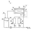
- FIG. 6 is a schematic view showing a main part of an organic material removing apparatus 2 which is another example of the organic material removing apparatus capable of performing the organic material removing method and the recycled material manufacturing method of the present embodiment.
- This embodiment demonstrates the case where the heated process liquid distribute
- the organic material removing device 2 includes a processing tank 11 that is a processing tank.
- the processing tank 11 is a substantially rectangular parallelepiped, and is disposed so that the longitudinal direction of the substantially rectangular parallelepiped is along the horizontal direction.
- An opening (not shown) is provided in the upper part of the processing tank 11 so that the container 12 can be accommodated or taken out.
- the opening (not shown) is closed with a lid (not shown) that can be opened and closed.
- the processing tank 11 stores a container 12 that stores a composite material including an inorganic material and an organic material that is decomposed by the processing liquid.
- a portion of the processing tank 11 in which the container 12 is accommodated is the accommodating portion 14.
- a processing liquid inflow portion 16 is provided at one end in the longitudinal direction of the processing tank 11, and a processing liquid outflow portion 18 is provided at the other end in the longitudinal direction.
- a baffle plate 22, which is one of rectifying means for rectifying the processing liquid 20, is provided between the storage section 14 and the portion where the processing liquid inflow section 16 is provided in the processing tank 11.
- a discharge valve 19 for discharging the processing liquid 20 from the processing tank 11 is provided at the bottom of the processing tank 11.
- the processing liquid 20 can be discharged from the processing tank 11. Yes.
- the other components of the organic material removing apparatus 2, the operation of the organic material removing apparatus 2, the processing conditions for removing the organic material, and the like can be the same as those of the organic material removing apparatus 1.
- the organic material removing apparatus including one processing tank has been described.
- the organic material removing apparatus used in this embodiment may include two or more processing tanks.
- the processing liquid flowing out from the processing liquid outflow portion in the first processing tank is transferred from the processing liquid inflow section in the second processing tank into the second processing tank. It can be set as the structure made to flow in.
Landscapes
- Chemical & Material Sciences (AREA)
- Chemical Kinetics & Catalysis (AREA)
- Health & Medical Sciences (AREA)
- Engineering & Computer Science (AREA)
- Environmental & Geological Engineering (AREA)
- Organic Chemistry (AREA)
- Life Sciences & Earth Sciences (AREA)
- Polymers & Plastics (AREA)
- Medicinal Chemistry (AREA)
- Sustainable Development (AREA)
- General Health & Medical Sciences (AREA)
- Thermal Sciences (AREA)
- Physics & Mathematics (AREA)
- Toxicology (AREA)
- General Chemical & Material Sciences (AREA)
- Separation, Recovery Or Treatment Of Waste Materials Containing Plastics (AREA)
Abstract
La présente invention concerne un procédé d'élimination de matériau organique qui comprend une étape de mise en contact d'un flux unidirectionnel de liquide de traitement chauffé avec un matériau composite en forme de plaque qui comprend un matériau inorganique et un matériau organique qui est décomposé par le liquide de traitement, permettant ainsi l'élimination du matériau organique. Le matériau composite est agencé de telle sorte que le liquide de traitement entre en contact avec au moins une partie d'une surface de plaque du matériau composite.
Priority Applications (4)
| Application Number | Priority Date | Filing Date | Title |
|---|---|---|---|
| CN201680083218.5A CN108779285A (zh) | 2016-03-08 | 2016-03-08 | 有机材料除去方法以及再生材料的制造方法 |
| JP2017539055A JP6785425B2 (ja) | 2016-03-08 | 2016-03-08 | 有機材料除去方法及び再生材料の製造方法 |
| PCT/JP2016/057157 WO2017154100A1 (fr) | 2016-03-08 | 2016-03-08 | Procédé d'élimination de matériau organique et procédé de production de matériau recyclé |
| US15/742,824 US20180371205A1 (en) | 2016-03-08 | 2016-03-08 | Organic material removing method and method of producing recycled material |
Applications Claiming Priority (1)
| Application Number | Priority Date | Filing Date | Title |
|---|---|---|---|
| PCT/JP2016/057157 WO2017154100A1 (fr) | 2016-03-08 | 2016-03-08 | Procédé d'élimination de matériau organique et procédé de production de matériau recyclé |
Publications (1)
| Publication Number | Publication Date |
|---|---|
| WO2017154100A1 true WO2017154100A1 (fr) | 2017-09-14 |
Family
ID=59790396
Family Applications (1)
| Application Number | Title | Priority Date | Filing Date |
|---|---|---|---|
| PCT/JP2016/057157 Ceased WO2017154100A1 (fr) | 2016-03-08 | 2016-03-08 | Procédé d'élimination de matériau organique et procédé de production de matériau recyclé |
Country Status (4)
| Country | Link |
|---|---|
| US (1) | US20180371205A1 (fr) |
| JP (1) | JP6785425B2 (fr) |
| CN (1) | CN108779285A (fr) |
| WO (1) | WO2017154100A1 (fr) |
Cited By (1)
| Publication number | Priority date | Publication date | Assignee | Title |
|---|---|---|---|---|
| WO2023037943A1 (fr) * | 2021-09-10 | 2023-03-16 | 三菱ケミカル株式会社 | Procédé de production de fibres de carbone récupérées |
Citations (5)
| Publication number | Priority date | Publication date | Assignee | Title |
|---|---|---|---|---|
| JPH10314713A (ja) * | 1997-03-17 | 1998-12-02 | Toshiba Corp | 混合廃棄物の処理方法および処理装置 |
| JP2007246831A (ja) * | 2006-03-17 | 2007-09-27 | Hitachi Chem Co Ltd | 繊維強化プラスチックに含まれる繊維および充填材の分離回収方法ならびに回収材を用いた成形品 |
| JP2011520004A (ja) * | 2008-05-09 | 2011-07-14 | ソルヴェイ(ソシエテ アノニム) | 繊維強化ポリマーをベースとする物品のリサイクル方法 |
| JP2013006948A (ja) * | 2011-06-24 | 2013-01-10 | Aasu Recycle Kk | 複合系プラスチック廃棄物の分離回収方法及びそれに用いる分離回収装置 |
| JP2013091694A (ja) * | 2011-10-25 | 2013-05-16 | Hitachi Chemical Co Ltd | 複合体の溶解処理装置、及び、複合体の溶解処理方法 |
Family Cites Families (9)
| Publication number | Priority date | Publication date | Assignee | Title |
|---|---|---|---|---|
| US3235342A (en) * | 1962-10-02 | 1966-02-15 | Fmc Corp | Baffle-kettle reactor |
| US4055480A (en) * | 1974-01-14 | 1977-10-25 | Standard Oil Company | Multi-phase separation methods and apparatus |
| US6464797B1 (en) * | 1999-07-28 | 2002-10-15 | Ricoh Company, Ltd. | Method of separating electrophotographic carrier compositions and recycling the compositions |
| KR101134154B1 (ko) * | 2009-10-30 | 2012-04-09 | 한국철도기술연구원 | 폐 씨에프알피로부터 탄소섬유를 회수하는 순환흐름 반응기 및 그 방법 |
| JP5614089B2 (ja) * | 2010-04-30 | 2014-10-29 | 日立化成株式会社 | 樹脂複合物の溶解処理装置、及び、樹脂複合物の溶解処理方法 |
| KR101189436B1 (ko) * | 2011-02-22 | 2012-10-10 | 한국철도기술연구원 | 폐 씨에프알피의 탄소섬유 회수용 연속식 순환흐름 반응장치 및 그 방법 |
| JP5884392B2 (ja) * | 2011-10-12 | 2016-03-15 | 日立化成株式会社 | 複合体の溶解処理装置、及び、複合体の溶解処理方法 |
| JP5880960B2 (ja) * | 2012-05-08 | 2016-03-09 | 日立化成株式会社 | 複合体からの不溶物の回収方法 |
| JP2015192033A (ja) * | 2014-03-28 | 2015-11-02 | 株式会社Screenホールディングス | 基板処理装置、および基板処理方法 |
-
2016
- 2016-03-08 WO PCT/JP2016/057157 patent/WO2017154100A1/fr not_active Ceased
- 2016-03-08 US US15/742,824 patent/US20180371205A1/en not_active Abandoned
- 2016-03-08 JP JP2017539055A patent/JP6785425B2/ja not_active Expired - Fee Related
- 2016-03-08 CN CN201680083218.5A patent/CN108779285A/zh active Pending
Patent Citations (5)
| Publication number | Priority date | Publication date | Assignee | Title |
|---|---|---|---|---|
| JPH10314713A (ja) * | 1997-03-17 | 1998-12-02 | Toshiba Corp | 混合廃棄物の処理方法および処理装置 |
| JP2007246831A (ja) * | 2006-03-17 | 2007-09-27 | Hitachi Chem Co Ltd | 繊維強化プラスチックに含まれる繊維および充填材の分離回収方法ならびに回収材を用いた成形品 |
| JP2011520004A (ja) * | 2008-05-09 | 2011-07-14 | ソルヴェイ(ソシエテ アノニム) | 繊維強化ポリマーをベースとする物品のリサイクル方法 |
| JP2013006948A (ja) * | 2011-06-24 | 2013-01-10 | Aasu Recycle Kk | 複合系プラスチック廃棄物の分離回収方法及びそれに用いる分離回収装置 |
| JP2013091694A (ja) * | 2011-10-25 | 2013-05-16 | Hitachi Chemical Co Ltd | 複合体の溶解処理装置、及び、複合体の溶解処理方法 |
Cited By (1)
| Publication number | Priority date | Publication date | Assignee | Title |
|---|---|---|---|---|
| WO2023037943A1 (fr) * | 2021-09-10 | 2023-03-16 | 三菱ケミカル株式会社 | Procédé de production de fibres de carbone récupérées |
Also Published As
| Publication number | Publication date |
|---|---|
| JPWO2017154100A1 (ja) | 2019-01-10 |
| US20180371205A1 (en) | 2018-12-27 |
| CN108779285A (zh) | 2018-11-09 |
| JP6785425B2 (ja) | 2020-11-18 |
Similar Documents
| Publication | Publication Date | Title |
|---|---|---|
| KR101134154B1 (ko) | 폐 씨에프알피로부터 탄소섬유를 회수하는 순환흐름 반응기 및 그 방법 | |
| JP6785424B2 (ja) | 有機材料除去装置 | |
| KR101189436B1 (ko) | 폐 씨에프알피의 탄소섬유 회수용 연속식 순환흐름 반응장치 및 그 방법 | |
| JP5614089B2 (ja) | 樹脂複合物の溶解処理装置、及び、樹脂複合物の溶解処理方法 | |
| JP5880960B2 (ja) | 複合体からの不溶物の回収方法 | |
| KR20230107389A (ko) | 보강섬유 회수용 반응장치 및 재생 보강섬유의 제조방법 | |
| US10774194B2 (en) | Method of separating inorganic material, method of producing reprocessed material and method of removing organic substance | |
| WO2017154100A1 (fr) | Procédé d'élimination de matériau organique et procédé de production de matériau recyclé | |
| JP2019044100A (ja) | 有機材料除去装置 | |
| JP5884392B2 (ja) | 複合体の溶解処理装置、及び、複合体の溶解処理方法 | |
| JP2019044101A (ja) | 有機材料除去方法及び再生材料の製造方法 | |
| US20190047182A1 (en) | Methods and systems for rubber removal from vulcanization molds | |
| EP4633897A1 (fr) | Procédé de traitement d'articles auxiliaires utilisés dans la fabrication d'un article contenant un polymère époxy | |
| JP5879923B2 (ja) | 複合体の溶解処理装置、及び、複合体の溶解処理方法 | |
| CN100408295C (zh) | 发泡苯乙烯树脂的回收方法 | |
| JP7661895B2 (ja) | 乾燥システム、ベントシステム及び製造システム | |
| JP6687030B2 (ja) | 無機材料の分離方法、再生材料の製造方法、及び有機物の除去方法 | |
| JP2013082851A (ja) | 樹脂複合体の溶解処理装置、及び、樹脂複合体の溶解処理方法 | |
| JP2012031296A (ja) | 複合材料の亜臨界水分解により得られる未溶解固形分の回収方法と再利用方法ならびに回収装置 | |
| JP2020001021A (ja) | 無機材料の処理方法及び再生材料の製造方法 | |
| JPH09291170A (ja) | 発泡樹脂の収縮方法及びその装置 | |
| CN110947975A (zh) | 废旧铝箔利用方法 |
Legal Events
| Date | Code | Title | Description |
|---|---|---|---|
| ENP | Entry into the national phase |
Ref document number: 2017539055 Country of ref document: JP Kind code of ref document: A |
|
| NENP | Non-entry into the national phase |
Ref country code: DE |
|
| 121 | Ep: the epo has been informed by wipo that ep was designated in this application |
Ref document number: 16893432 Country of ref document: EP Kind code of ref document: A1 |
|
| 122 | Ep: pct application non-entry in european phase |
Ref document number: 16893432 Country of ref document: EP Kind code of ref document: A1 |