WO2017154111A1 - Dispositif de génération de lumière ultraviolette extrême - Google Patents
Dispositif de génération de lumière ultraviolette extrême Download PDFInfo
- Publication number
- WO2017154111A1 WO2017154111A1 PCT/JP2016/057196 JP2016057196W WO2017154111A1 WO 2017154111 A1 WO2017154111 A1 WO 2017154111A1 JP 2016057196 W JP2016057196 W JP 2016057196W WO 2017154111 A1 WO2017154111 A1 WO 2017154111A1
- Authority
- WO
- WIPO (PCT)
- Prior art keywords
- target
- euv light
- plasma
- control unit
- ultraviolet light
- Prior art date
- Legal status (The legal status is an assumption and is not a legal conclusion. Google has not performed a legal analysis and makes no representation as to the accuracy of the status listed.)
- Ceased
Links
Images






Classifications
-
- H—ELECTRICITY
- H05—ELECTRIC TECHNIQUES NOT OTHERWISE PROVIDED FOR
- H05G—X-RAY TECHNIQUE
- H05G2/00—Apparatus or processes specially adapted for producing X-rays, not involving X-ray tubes, e.g. involving generation of a plasma
- H05G2/001—Production of X-ray radiation generated from plasma
- H05G2/008—Production of X-ray radiation generated from plasma involving an energy-carrying beam in the process of plasma generation
- H05G2/0082—Production of X-ray radiation generated from plasma involving an energy-carrying beam in the process of plasma generation the energy-carrying beam being a laser beam
- H05G2/0086—Optical arrangements for conveying the laser beam to the plasma generation location
-
- G—PHYSICS
- G01—MEASURING; TESTING
- G01J—MEASUREMENT OF INTENSITY, VELOCITY, SPECTRAL CONTENT, POLARISATION, PHASE OR PULSE CHARACTERISTICS OF INFRARED, VISIBLE OR ULTRAVIOLET LIGHT; COLORIMETRY; RADIATION PYROMETRY
- G01J1/00—Photometry, e.g. photographic exposure meter
- G01J1/42—Photometry, e.g. photographic exposure meter using electric radiation detectors
- G01J1/4209—Photoelectric exposure meters for determining the exposure time in recording or reproducing
-
- G—PHYSICS
- G01—MEASURING; TESTING
- G01J—MEASUREMENT OF INTENSITY, VELOCITY, SPECTRAL CONTENT, POLARISATION, PHASE OR PULSE CHARACTERISTICS OF INFRARED, VISIBLE OR ULTRAVIOLET LIGHT; COLORIMETRY; RADIATION PYROMETRY
- G01J1/00—Photometry, e.g. photographic exposure meter
- G01J1/42—Photometry, e.g. photographic exposure meter using electric radiation detectors
- G01J1/4228—Photometry, e.g. photographic exposure meter using electric radiation detectors arrangements with two or more detectors, e.g. for sensitivity compensation
-
- G—PHYSICS
- G01—MEASURING; TESTING
- G01J—MEASUREMENT OF INTENSITY, VELOCITY, SPECTRAL CONTENT, POLARISATION, PHASE OR PULSE CHARACTERISTICS OF INFRARED, VISIBLE OR ULTRAVIOLET LIGHT; COLORIMETRY; RADIATION PYROMETRY
- G01J1/00—Photometry, e.g. photographic exposure meter
- G01J1/42—Photometry, e.g. photographic exposure meter using electric radiation detectors
- G01J1/4257—Photometry, e.g. photographic exposure meter using electric radiation detectors applied to monitoring the characteristics of a beam, e.g. laser beam, headlamp beam
-
- G—PHYSICS
- G01—MEASURING; TESTING
- G01J—MEASUREMENT OF INTENSITY, VELOCITY, SPECTRAL CONTENT, POLARISATION, PHASE OR PULSE CHARACTERISTICS OF INFRARED, VISIBLE OR ULTRAVIOLET LIGHT; COLORIMETRY; RADIATION PYROMETRY
- G01J1/00—Photometry, e.g. photographic exposure meter
- G01J1/42—Photometry, e.g. photographic exposure meter using electric radiation detectors
- G01J1/429—Photometry, e.g. photographic exposure meter using electric radiation detectors applied to measurement of ultraviolet light
-
- G—PHYSICS
- G03—PHOTOGRAPHY; CINEMATOGRAPHY; ANALOGOUS TECHNIQUES USING WAVES OTHER THAN OPTICAL WAVES; ELECTROGRAPHY; HOLOGRAPHY
- G03F—PHOTOMECHANICAL PRODUCTION OF TEXTURED OR PATTERNED SURFACES, e.g. FOR PRINTING, FOR PROCESSING OF SEMICONDUCTOR DEVICES; MATERIALS THEREFOR; ORIGINALS THEREFOR; APPARATUS SPECIALLY ADAPTED THEREFOR
- G03F7/00—Photomechanical, e.g. photolithographic, production of textured or patterned surfaces, e.g. printing surfaces; Materials therefor, e.g. comprising photoresists; Apparatus specially adapted therefor
- G03F7/70—Microphotolithographic exposure; Apparatus therefor
- G03F7/70008—Production of exposure light, i.e. light sources
- G03F7/70033—Production of exposure light, i.e. light sources by plasma extreme ultraviolet [EUV] sources
-
- H—ELECTRICITY
- H05—ELECTRIC TECHNIQUES NOT OTHERWISE PROVIDED FOR
- H05G—X-RAY TECHNIQUE
- H05G2/00—Apparatus or processes specially adapted for producing X-rays, not involving X-ray tubes, e.g. involving generation of a plasma
- H05G2/001—Production of X-ray radiation generated from plasma
- H05G2/008—Production of X-ray radiation generated from plasma involving an energy-carrying beam in the process of plasma generation
- H05G2/0082—Production of X-ray radiation generated from plasma involving an energy-carrying beam in the process of plasma generation the energy-carrying beam being a laser beam
- H05G2/0084—Control of the laser beam
-
- G—PHYSICS
- G01—MEASURING; TESTING
- G01J—MEASUREMENT OF INTENSITY, VELOCITY, SPECTRAL CONTENT, POLARISATION, PHASE OR PULSE CHARACTERISTICS OF INFRARED, VISIBLE OR ULTRAVIOLET LIGHT; COLORIMETRY; RADIATION PYROMETRY
- G01J1/00—Photometry, e.g. photographic exposure meter
- G01J1/42—Photometry, e.g. photographic exposure meter using electric radiation detectors
- G01J2001/4247—Photometry, e.g. photographic exposure meter using electric radiation detectors for testing lamps or other light sources
Definitions
- the “target” is an object to be irradiated with laser light introduced into the chamber.
- the target irradiated with the laser light is turned into plasma and emits light including EUV light.
- the “plasma generation region” is a predetermined region in the chamber.
- the plasma generation region is a region where the target output to the chamber is irradiated with laser light and the target is turned into plasma.
- the “target trajectory” is a path along which the target output in the chamber travels. The target trajectory intersects the optical path of the laser light introduced into the chamber in the plasma generation region.
- the “optical path axis” is an axis passing through the center of the beam cross section of the laser light along the traveling direction of the laser light.
- the control unit 8 changes the delay time Td using Equation 1 and Equation 2, so that the relative positional relationship between the position of the target 27 supplied to the plasma generation region R1 and the condensing position of the pulsed laser beam 31 is changed. So that the irradiation timing of the pulse laser beam 31 can be changed.
- the control unit 8 changes the delay time Td using Equation 1 and Equation 2, thereby making the relative position between the position of the target 27 supplied to the plasma generation region R1 and the condensing position of the pulsed laser light 31. Therefore, the generation position of the EUV light 277 can be moved while maintaining a proper positional relationship.
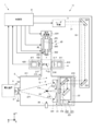
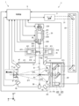
- FIG. 4 is a diagram for explaining the configuration of the EUV light generation apparatus 1 according to the first embodiment.
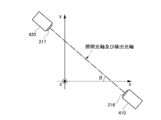
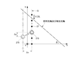
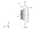
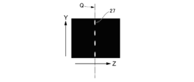
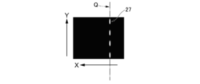
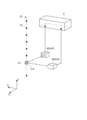
- FIG. 5 is a diagram for explaining the arrangement of the EUV light sensors 43 shown in FIG.
- FIG. 6 shows a view of the arrangement of the EUV light sensor 43 shown in FIG. 5 as viewed from the direction opposite to the X-axis direction.
- the EUV light sensor 43 is a sensor that measures the energy of the EUV light 277 contained in the radiation light 276 emitted from the plasma 275.
- the EUV light sensor 43 is composed of a plurality of EUV light sensors 43.
- the plurality of EUV light sensors 43 includes, for example, EUV light sensors 43a to 43c.
- the position of the center of gravity of the EUV light 277 is an index for evaluating whether the irradiation condition of the pulse laser light 31 on the target 27 satisfies the performance of the EUV light 277. Controlling the position of the center of gravity of the EUV light 277 to be a predetermined position means that the target 27 is appropriately irradiated with the pulse laser light 31.
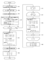
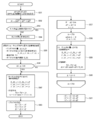
- step S ⁇ b> 3 the control unit 8 acquires the current position of the plasma 275 and specifies the moving distance of the plasma 275.
- the current position of the plasma 275 is the position of the plasma 275 held by the control unit 8 at the start of the EUV light movement process.
- the current position of the plasma 275 may be the generation position of the EUV light 277 commanded by the exposure apparatus 9 during the previous EUV light movement process. Since the radiation light 276 including the EUV light 277 is emitted radially from the plasma 275, the generation position of the EUV light 277 is correlated with the position of the plasma 275. When the generation position of the EUV light 277 is moved, the position of the plasma 275 is moved.
- step S8 the control unit 8 controls at least one of the stage 26, the manipulator 224, and the irradiation timing at a time.
- step S ⁇ b> 11 the control unit 8 receives a command from the exposure apparatus 9 for moving the generation position of the EUV light 277.
- the command from the exposure apparatus 9 includes a difference value ⁇ P ( ⁇ X, ⁇ Y, ⁇ Z) between the plasma current position and the plasma target position. That is, the difference value ⁇ P is a deviation between the current plasma position and the target plasma position.
- the command from the exposure apparatus 9 is a command for instructing the control unit 8 to move the position of the plasma 275 according to the difference value ⁇ P.
- step S ⁇ b> 16 the control unit 8 sets parameters N, dP, and k for moving the position of the plasma 275 by the allowable value Lth, as shown in Equations 7 to 9.
- the control unit 8 sets the quotient obtained by calculating the right side of Equation 7 to N.
- N is a natural number, and is a value obtained by rounding down the remainder obtained by calculating the right side of Equation 7.
- N is the number of times the position of the plasma 275 is moved by the allowable value Lth.
- N is a number that defines how many times the control unit 8 executes control to move the position of the plasma 275 by the allowable value Lth when the position of the plasma 275 is moved by the movement distance ⁇ L. is there.
- the control unit 8 can move the generation position of the plasma 275 to a position according to a command from the exposure apparatus 9 while generating the EUV light 277 while moving the position of the plasma 275 a plurality of times by the allowable value Lth.
- the control unit 8 can move the generation position of the EUV light 277 as linearly as possible while maintaining the performance of the EUV light 277.
- the EUV light generation apparatus 1 of the first embodiment generates the EUV light 277 while maintaining the performance of the EUV light 277 when moving the generation position of the EUV light 277 based on a command from the exposure apparatus 9.
- the generation position can be moved in a short time.
- the control unit 8 determines the driving amount of the manipulator 224 in the direction along the X axis as dX, and determines the driving amount of the manipulator 224 in the direction along the Y axis as dY.
- the control unit 8 determines the change amount dt of the delay time Td using dX and dY, as shown in Expression 22.
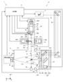
- FIG. 15 is a diagram for explaining the configuration of the EUV light generation apparatus 1 according to the third embodiment.
- FIG. 16 is a diagram for explaining the configuration of the plurality of first image sensors 45 shown in FIG.
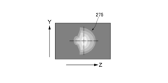
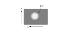
- the imaging units 453 and 454 included in the plurality of first image sensors 45 can acquire a still image of the plasma 275 as illustrated in FIGS. 17 and 18.
- the control unit 8 can measure each coordinate component at the position of the plasma 275 generated at a certain time.
- Each of the plurality of first image sensors 45 transmits a signal including the acquired image to the control unit 8.
- the control unit 8 determines the position of the plasma 275 held by the control unit 8 at the start of the EUV light movement process as the current position of the plasma 275 (Xi, Yi, Zi). And Alternatively, as in the second embodiment, the control unit 8 determines the position of the target 27 measured using the plurality of images acquired by the first and second image sensors 45 and 47 as the current position of the plasma 275. Estimated as (Xi, Yi, Zi). Alternatively, as in the third embodiment, the control unit 8 determines the position of the plasma 275 measured using a plurality of images acquired by the plurality of first image sensors 45 as the current position of the plasma 275 (Xi, Yi, Zi).
- step S62 the control unit 8 sets at least one of the change amount of the control target position of the target 27 and the change amount of the delay time Td as a difference value ⁇ P ( ⁇ X, [Delta] Y, [Delta] Z).
- the control unit 8 determines the change amount of the X-axis coordinate component of the control target position at the position of the target 27 as ⁇ X, and changes the Y-axis coordinate component of the control target position.
- the amount is determined to be ⁇ Y
- the change amount of the Z-axis coordinate component of the control target position is determined to be ⁇ Z.
- the control unit 8 determines the change amount ⁇ t of the delay time Td using ⁇ X and ⁇ Y, as shown in Equation 29.
Landscapes
- Physics & Mathematics (AREA)
- General Physics & Mathematics (AREA)
- Optics & Photonics (AREA)
- Spectroscopy & Molecular Physics (AREA)
- Engineering & Computer Science (AREA)
- Plasma & Fusion (AREA)
- Exposure And Positioning Against Photoresist Photosensitive Materials (AREA)
- X-Ray Techniques (AREA)
Abstract
L'invention concerne un dispositif de génération de lumière ultraviolette extrême qui déplace, sur la base d'une commande donnée par un dispositif externe, la position de génération de lumière ultraviolette extrême. Le dispositif de génération de lumière ultraviolette extrême comporte : une chambre, dans laquelle est générée une lumière ultraviolette extrême à partir d'une cible par exposition de la cible à une lumière laser, ladite cible ayant été disposée à l'intérieur ; un appareil d'alimentation en cible qui délivre et fournit la cible à l'intérieur de la chambre ; un miroir de collecte de lumière qui collecte la lumière laser vers la cible fournie à l'intérieur de la chambre ; un étage qui régule la position de l'appareil d'alimentation en cible ; un manipulateur qui régule la position du miroir de collecte de lumière ; et une unité de commande conçue de telle sorte que la synchronisation d'exposition laser par rapport à l'étage et/ou la synchronisation d'exposition laser par rapport au manipulateur et/ou la synchronisation d'exposition laser par rapport à la cible peuvent être contrôlées au moyen d'un système d'action directe au moment du déplacement de la position de génération lors de la génération de la lumière ultraviolette extrême.
Priority Applications (4)
| Application Number | Priority Date | Filing Date | Title |
|---|---|---|---|
| PCT/JP2016/057196 WO2017154111A1 (fr) | 2016-03-08 | 2016-03-08 | Dispositif de génération de lumière ultraviolette extrême |
| PCT/JP2017/005996 WO2017154528A1 (fr) | 2016-03-08 | 2017-02-17 | Appareil de production de lumière dans l'ultraviolet extrême |
| JP2018504332A JP6763015B2 (ja) | 2016-03-08 | 2017-02-17 | 極端紫外光生成装置 |
| US16/055,274 US10225918B2 (en) | 2016-03-08 | 2018-08-06 | Extreme ultraviolet light generating apparatus |
Applications Claiming Priority (1)
| Application Number | Priority Date | Filing Date | Title |
|---|---|---|---|
| PCT/JP2016/057196 WO2017154111A1 (fr) | 2016-03-08 | 2016-03-08 | Dispositif de génération de lumière ultraviolette extrême |
Publications (1)
| Publication Number | Publication Date |
|---|---|
| WO2017154111A1 true WO2017154111A1 (fr) | 2017-09-14 |
Family
ID=59790303
Family Applications (2)
| Application Number | Title | Priority Date | Filing Date |
|---|---|---|---|
| PCT/JP2016/057196 Ceased WO2017154111A1 (fr) | 2016-03-08 | 2016-03-08 | Dispositif de génération de lumière ultraviolette extrême |
| PCT/JP2017/005996 Ceased WO2017154528A1 (fr) | 2016-03-08 | 2017-02-17 | Appareil de production de lumière dans l'ultraviolet extrême |
Family Applications After (1)
| Application Number | Title | Priority Date | Filing Date |
|---|---|---|---|
| PCT/JP2017/005996 Ceased WO2017154528A1 (fr) | 2016-03-08 | 2017-02-17 | Appareil de production de lumière dans l'ultraviolet extrême |
Country Status (3)
| Country | Link |
|---|---|
| US (1) | US10225918B2 (fr) |
| JP (1) | JP6763015B2 (fr) |
| WO (2) | WO2017154111A1 (fr) |
Families Citing this family (11)
| Publication number | Priority date | Publication date | Assignee | Title |
|---|---|---|---|---|
| WO2017090167A1 (fr) * | 2015-11-26 | 2017-06-01 | ギガフォトン株式会社 | Dispositif de génération de lumière ultraviolette extrême |
| WO2017187571A1 (fr) * | 2016-04-27 | 2017-11-02 | ギガフォトン株式会社 | Unité capteur de lumière ultraviolette extrême et dispositif de génération de lumière ultraviolette extrême |
| WO2019175964A1 (fr) * | 2018-03-13 | 2019-09-19 | ギガフォトン株式会社 | Système de génération de lumière ultraviolette extrême et procédé de fabrication de dispositif |
| WO2020165942A1 (fr) * | 2019-02-12 | 2020-08-20 | ギガフォトン株式会社 | Dispositif de génération de lumière ultraviolette extrême, procédé de commande de cible et procédé de production de dispositif électronique |
| KR102048529B1 (ko) * | 2019-03-06 | 2019-11-25 | 엘아이지넥스원 주식회사 | 평면 미러를 구비하는 레이저의 빔 집속 장치 및 이를 포함한 레이저 시스템 |
| KR102031927B1 (ko) * | 2019-03-13 | 2019-10-14 | 엘아이지넥스원 주식회사 | 레이저의 추적 조준 장치 및 이의 일체형 빔 정렬 광학계 |
| US11650508B2 (en) * | 2020-06-12 | 2023-05-16 | Taiwan Semiconductor Manufacturing Co., Ltd. | Plasma position control for extreme ultraviolet lithography light sources |
| JP2023135426A (ja) * | 2022-03-15 | 2023-09-28 | ギガフォトン株式会社 | 極端紫外光生成装置及び電子デバイスの製造方法 |
| US12149665B2 (en) * | 2022-10-13 | 2024-11-19 | Canon Kabushiki Kaisha | Image reading apparatus and computer-readable storage medium |
| JP7604536B2 (ja) * | 2023-02-28 | 2024-12-23 | レーザーテック株式会社 | 位置検出装置及び位置検出方法 |
| JP2025086739A (ja) * | 2023-11-28 | 2025-06-09 | ギガフォトン株式会社 | Euv光生成システムの性能回復方法、euv光生成システム、及びプロセッサ |
Citations (6)
| Publication number | Priority date | Publication date | Assignee | Title |
|---|---|---|---|---|
| JP2007528607A (ja) * | 2004-03-10 | 2007-10-11 | サイマー インコーポレイテッド | Euv光源 |
| JP2013105725A (ja) * | 2011-11-16 | 2013-05-30 | Gigaphoton Inc | 極端紫外光生成装置および極端紫外光生成方法 |
| JP2014086523A (ja) * | 2012-10-23 | 2014-05-12 | Gigaphoton Inc | 極端紫外光生成装置 |
| JP2014531743A (ja) * | 2011-08-19 | 2014-11-27 | エーエスエムエル ネザーランズ ビー.ブイ. | 光ビームアラインメントのためのエネルギセンサ |
| JP2015015251A (ja) * | 2009-07-29 | 2015-01-22 | ギガフォトン株式会社 | 極端紫外光源装置、極端紫外光源装置の制御方法、およびそのプログラムを記録した記録媒体 |
| JP2015532505A (ja) * | 2012-09-28 | 2015-11-09 | エーエスエムエル ネザーランズ ビー.ブイ. | Euv光のためのターゲット材料プッシュアウトの事前補償 |
Family Cites Families (7)
| Publication number | Priority date | Publication date | Assignee | Title |
|---|---|---|---|---|
| US7217940B2 (en) | 2003-04-08 | 2007-05-15 | Cymer, Inc. | Collector for EUV light source |
| JP2004140390A (ja) * | 2003-12-01 | 2004-05-13 | Canon Inc | 照明光学系、露光装置及びデバイス製造方法 |
| JP5218014B2 (ja) * | 2008-12-17 | 2013-06-26 | ウシオ電機株式会社 | 極端紫外光光源装置および極端紫外光光源装置の保守方法 |
| JP5765730B2 (ja) | 2010-03-11 | 2015-08-19 | ギガフォトン株式会社 | 極端紫外光生成装置 |
| JP5856898B2 (ja) | 2011-06-02 | 2016-02-10 | ギガフォトン株式会社 | 極端紫外光生成装置および極端紫外光生成方法 |
| US8598552B1 (en) * | 2012-05-31 | 2013-12-03 | Cymer, Inc. | System and method to optimize extreme ultraviolet light generation |
| JP6649958B2 (ja) * | 2015-10-02 | 2020-02-19 | ギガフォトン株式会社 | 極端紫外光生成システム |
-
2016
- 2016-03-08 WO PCT/JP2016/057196 patent/WO2017154111A1/fr not_active Ceased
-
2017
- 2017-02-17 JP JP2018504332A patent/JP6763015B2/ja active Active
- 2017-02-17 WO PCT/JP2017/005996 patent/WO2017154528A1/fr not_active Ceased
-
2018
- 2018-08-06 US US16/055,274 patent/US10225918B2/en active Active
Patent Citations (6)
| Publication number | Priority date | Publication date | Assignee | Title |
|---|---|---|---|---|
| JP2007528607A (ja) * | 2004-03-10 | 2007-10-11 | サイマー インコーポレイテッド | Euv光源 |
| JP2015015251A (ja) * | 2009-07-29 | 2015-01-22 | ギガフォトン株式会社 | 極端紫外光源装置、極端紫外光源装置の制御方法、およびそのプログラムを記録した記録媒体 |
| JP2014531743A (ja) * | 2011-08-19 | 2014-11-27 | エーエスエムエル ネザーランズ ビー.ブイ. | 光ビームアラインメントのためのエネルギセンサ |
| JP2013105725A (ja) * | 2011-11-16 | 2013-05-30 | Gigaphoton Inc | 極端紫外光生成装置および極端紫外光生成方法 |
| JP2015532505A (ja) * | 2012-09-28 | 2015-11-09 | エーエスエムエル ネザーランズ ビー.ブイ. | Euv光のためのターゲット材料プッシュアウトの事前補償 |
| JP2014086523A (ja) * | 2012-10-23 | 2014-05-12 | Gigaphoton Inc | 極端紫外光生成装置 |
Also Published As
| Publication number | Publication date |
|---|---|
| WO2017154528A1 (fr) | 2017-09-14 |
| JPWO2017154528A1 (ja) | 2019-01-31 |
| US10225918B2 (en) | 2019-03-05 |
| JP6763015B2 (ja) | 2020-09-30 |
| US20180352641A1 (en) | 2018-12-06 |
Similar Documents
| Publication | Publication Date | Title |
|---|---|---|
| JP6763015B2 (ja) | 極端紫外光生成装置 | |
| JP6649958B2 (ja) | 極端紫外光生成システム | |
| US9241395B2 (en) | System and method for controlling droplet timing in an LPP EUV light source | |
| US8809823B1 (en) | System and method for controlling droplet timing and steering in an LPP EUV light source | |
| US10102938B2 (en) | Extreme ultraviolet light generating apparatus | |
| JP6799583B2 (ja) | 極端紫外光生成装置及び極端紫外光の重心位置の制御方法 | |
| KR20160062053A (ko) | Euv 광원 내에서 타겟 재료의 액적을 제어하기 위한 시스템 및 방법 | |
| WO2017130323A1 (fr) | Dispositif d'alimentation cible et dispositif de production de lumière ultraviolette extrême | |
| JP6866471B2 (ja) | Euv光生成装置 | |
| US10842010B2 (en) | Extreme ultraviolet light generation system | |
| JP6831364B2 (ja) | Lpp euv光源におけるソースレーザの発射を制御するためのシステム及び方法 | |
| WO2017130346A1 (fr) | Dispositif de génération de lumière ultraviolette extrême | |
| JP6378355B2 (ja) | 極端紫外光生成装置及び極端紫外光の生成方法 | |
| JPWO2017051454A1 (ja) | 極端紫外光生成装置 | |
| US20190289707A1 (en) | Extreme ultraviolet light generation system | |
| JPWO2017017834A1 (ja) | 極端紫外光生成装置 | |
| WO2019186754A1 (fr) | Système de génération de lumière ultraviolette extrême et procédé de fabrication de dispositif électronique | |
| WO2019092831A1 (fr) | Dispositif de génération de lumière ultraviolette extrême et procédé de fabrication de dispositif électronique |
Legal Events
| Date | Code | Title | Description |
|---|---|---|---|
| NENP | Non-entry into the national phase |
Ref country code: DE |
|
| WD | Withdrawal of designations after international publication |
Designated state(s): JP |
|
| 121 | Ep: the epo has been informed by wipo that ep was designated in this application |
Ref document number: 16893443 Country of ref document: EP Kind code of ref document: A1 |
|
| 122 | Ep: pct application non-entry in european phase |
Ref document number: 16893443 Country of ref document: EP Kind code of ref document: A1 |