WO2017154528A1 - Appareil de production de lumière dans l'ultraviolet extrême - Google Patents
Appareil de production de lumière dans l'ultraviolet extrême Download PDFInfo
- Publication number
- WO2017154528A1 WO2017154528A1 PCT/JP2017/005996 JP2017005996W WO2017154528A1 WO 2017154528 A1 WO2017154528 A1 WO 2017154528A1 JP 2017005996 W JP2017005996 W JP 2017005996W WO 2017154528 A1 WO2017154528 A1 WO 2017154528A1
- Authority
- WO
- WIPO (PCT)
- Prior art keywords
- target
- euv light
- control unit
- plasma
- ultraviolet light
- Prior art date
- Legal status (The legal status is an assumption and is not a legal conclusion. Google has not performed a legal analysis and makes no representation as to the accuracy of the status listed.)
- Ceased
Links
Images








Classifications
-
- H—ELECTRICITY
- H05—ELECTRIC TECHNIQUES NOT OTHERWISE PROVIDED FOR
- H05G—X-RAY TECHNIQUE
- H05G2/00—Apparatus or processes specially adapted for producing X-rays, not involving X-ray tubes, e.g. involving generation of a plasma
- H05G2/001—Production of X-ray radiation generated from plasma
- H05G2/008—Production of X-ray radiation generated from plasma involving an energy-carrying beam in the process of plasma generation
- H05G2/0082—Production of X-ray radiation generated from plasma involving an energy-carrying beam in the process of plasma generation the energy-carrying beam being a laser beam
- H05G2/0086—Optical arrangements for conveying the laser beam to the plasma generation location
-
- G—PHYSICS
- G01—MEASURING; TESTING
- G01J—MEASUREMENT OF INTENSITY, VELOCITY, SPECTRAL CONTENT, POLARISATION, PHASE OR PULSE CHARACTERISTICS OF INFRARED, VISIBLE OR ULTRAVIOLET LIGHT; COLORIMETRY; RADIATION PYROMETRY
- G01J1/00—Photometry, e.g. photographic exposure meter
- G01J1/42—Photometry, e.g. photographic exposure meter using electric radiation detectors
- G01J1/4209—Photoelectric exposure meters for determining the exposure time in recording or reproducing
-
- G—PHYSICS
- G01—MEASURING; TESTING
- G01J—MEASUREMENT OF INTENSITY, VELOCITY, SPECTRAL CONTENT, POLARISATION, PHASE OR PULSE CHARACTERISTICS OF INFRARED, VISIBLE OR ULTRAVIOLET LIGHT; COLORIMETRY; RADIATION PYROMETRY
- G01J1/00—Photometry, e.g. photographic exposure meter
- G01J1/42—Photometry, e.g. photographic exposure meter using electric radiation detectors
- G01J1/4228—Photometry, e.g. photographic exposure meter using electric radiation detectors arrangements with two or more detectors, e.g. for sensitivity compensation
-
- G—PHYSICS
- G01—MEASURING; TESTING
- G01J—MEASUREMENT OF INTENSITY, VELOCITY, SPECTRAL CONTENT, POLARISATION, PHASE OR PULSE CHARACTERISTICS OF INFRARED, VISIBLE OR ULTRAVIOLET LIGHT; COLORIMETRY; RADIATION PYROMETRY
- G01J1/00—Photometry, e.g. photographic exposure meter
- G01J1/42—Photometry, e.g. photographic exposure meter using electric radiation detectors
- G01J1/4257—Photometry, e.g. photographic exposure meter using electric radiation detectors applied to monitoring the characteristics of a beam, e.g. laser beam, headlamp beam
-
- G—PHYSICS
- G01—MEASURING; TESTING
- G01J—MEASUREMENT OF INTENSITY, VELOCITY, SPECTRAL CONTENT, POLARISATION, PHASE OR PULSE CHARACTERISTICS OF INFRARED, VISIBLE OR ULTRAVIOLET LIGHT; COLORIMETRY; RADIATION PYROMETRY
- G01J1/00—Photometry, e.g. photographic exposure meter
- G01J1/42—Photometry, e.g. photographic exposure meter using electric radiation detectors
- G01J1/429—Photometry, e.g. photographic exposure meter using electric radiation detectors applied to measurement of ultraviolet light
-
- G—PHYSICS
- G03—PHOTOGRAPHY; CINEMATOGRAPHY; ANALOGOUS TECHNIQUES USING WAVES OTHER THAN OPTICAL WAVES; ELECTROGRAPHY; HOLOGRAPHY
- G03F—PHOTOMECHANICAL PRODUCTION OF TEXTURED OR PATTERNED SURFACES, e.g. FOR PRINTING, FOR PROCESSING OF SEMICONDUCTOR DEVICES; MATERIALS THEREFOR; ORIGINALS THEREFOR; APPARATUS SPECIALLY ADAPTED THEREFOR
- G03F7/00—Photomechanical, e.g. photolithographic, production of textured or patterned surfaces, e.g. printing surfaces; Materials therefor, e.g. comprising photoresists; Apparatus specially adapted therefor
- G03F7/70—Microphotolithographic exposure; Apparatus therefor
- G03F7/70008—Production of exposure light, i.e. light sources
- G03F7/70033—Production of exposure light, i.e. light sources by plasma extreme ultraviolet [EUV] sources
-
- H—ELECTRICITY
- H05—ELECTRIC TECHNIQUES NOT OTHERWISE PROVIDED FOR
- H05G—X-RAY TECHNIQUE
- H05G2/00—Apparatus or processes specially adapted for producing X-rays, not involving X-ray tubes, e.g. involving generation of a plasma
- H05G2/001—Production of X-ray radiation generated from plasma
- H05G2/008—Production of X-ray radiation generated from plasma involving an energy-carrying beam in the process of plasma generation
- H05G2/0082—Production of X-ray radiation generated from plasma involving an energy-carrying beam in the process of plasma generation the energy-carrying beam being a laser beam
- H05G2/0084—Control of the laser beam
-
- G—PHYSICS
- G01—MEASURING; TESTING
- G01J—MEASUREMENT OF INTENSITY, VELOCITY, SPECTRAL CONTENT, POLARISATION, PHASE OR PULSE CHARACTERISTICS OF INFRARED, VISIBLE OR ULTRAVIOLET LIGHT; COLORIMETRY; RADIATION PYROMETRY
- G01J1/00—Photometry, e.g. photographic exposure meter
- G01J1/42—Photometry, e.g. photographic exposure meter using electric radiation detectors
- G01J2001/4247—Photometry, e.g. photographic exposure meter using electric radiation detectors for testing lamps or other light sources
Definitions
- This disclosure relates to an extreme ultraviolet light generation apparatus.
- an LPP Laser Produced Plasma
- DPP discharge Produced Plasma
- SR Synchrotron-Radiation
- An extreme ultraviolet light generation device is an extreme ultraviolet light generation device that moves a generation position of extreme ultraviolet light based on a command from an external device, and the target is supplied to the inside.
- a chamber in which extreme ultraviolet light is generated from the target by being irradiated with the laser light a target supplier that outputs the target and supplies the target into the chamber, and a light condensing that condenses the laser light on the target supplied in the chamber
- a control unit configured to be able to control at least one of the irradiation timings by a feed-forward method.
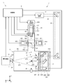
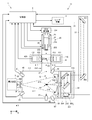
- FIG. 1 is a diagram for explaining the configuration of an EUV light generation apparatus of a comparative example.
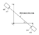
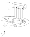
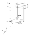
- FIG. 2 is a diagram for explaining the arrangement of the illumination unit and the detection unit shown in FIG.
- FIG. 3 shows a delay that is changed in order to change the irradiation timing of the pulsed laser light by the EUV light generation apparatus including the target detection sensor arranged as shown in FIG. 2 when moving the generation position of the EUV light. The figure for demonstrating time is shown.
- FIG. 4 is a diagram for explaining the configuration of the EUV light generation apparatus according to the first embodiment.
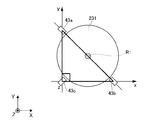
- FIG. 5 is a diagram for explaining the arrangement of the EUV light sensors shown in FIG. FIG.
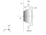
- FIG. 6 shows a view of the arrangement of the EUV light sensor shown in FIG.
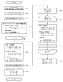
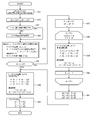
- FIG. 7 is a flowchart for explaining the outline of the EUV light movement process.
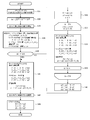
- FIG. 8 is a flowchart of the EUV light movement process executed by the control unit according to the first embodiment.
- FIG. 9 is a diagram for explaining the configuration of the EUV light generation apparatus according to the second embodiment.
- FIG. 10 is a diagram for explaining the configuration of the first and second image sensors shown in FIG.
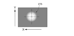
- FIG. 11 is a diagram for explaining an image acquired by the imaging unit included in the first image sensor shown in FIG.
- FIG. 12 is a diagram for explaining an image acquired by the imaging unit included in the second image sensor shown in FIG.
- FIG. 13 is a diagram for explaining an image acquired by the imaging unit included in the second image sensor shown in FIG.
- FIG. 10 is a diagram for explaining the configuration of the first and second image sensors shown in FIG.
- FIG. 11 is a diagram for explaining an image acquired by the imaging unit included in the first image sensor
- FIG. 14 is a flowchart of EUV light movement processing executed by the control unit according to the second embodiment.
- FIG. 15 is a diagram for explaining the configuration of the EUV light generation apparatus according to the third embodiment.
- FIG. 16 is a diagram for explaining the configuration of the plurality of first image sensors shown in FIG.
- FIG. 17 is a diagram for explaining an image acquired by the imaging unit included in the first image sensor shown in FIG.
- FIG. 18 is a view for explaining an image acquired by the imaging unit included in the first image sensor shown in FIG.
- FIG. 19 shows a flowchart of EUV light movement processing executed by the control unit according to the fourth embodiment.
- FIG. 20 is a diagram for explaining a configuration of an EUV light generation apparatus according to the fifth embodiment.
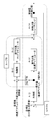
- FIG. 21 is a diagram for explaining the flow of the EUV light barycenter control of the EUV light movement process executed by the control unit according to the fifth embodiment.
- the “target” is an object to be irradiated with laser light introduced into the chamber.
- the target irradiated with the laser light is turned into plasma and emits light including EUV light.
- Plasma generation region is a predetermined region in the chamber.
- the plasma generation region is a region where the target output to the chamber is irradiated with laser light and the target is turned into plasma.
- Target trajectory is a path along which the target output in the chamber travels. The target trajectory intersects the optical path of the laser light introduced into the chamber in the plasma generation region.
- optical path axis is an axis passing through the center of the beam cross section of the laser light along the traveling direction of the laser light.
- the optical path is a path through which the laser beam passes.
- the optical path includes an optical path axis.
- the “Z-axis direction” is a traveling direction of the laser light when the laser light introduced into the chamber travels toward the plasma generation region.
- the Z-axis direction may be substantially the same as the direction in which the EUV light generation apparatus outputs EUV light.
- Y-axis direction is a direction opposite to the direction in which the target supplier outputs the target into the chamber.
- the Y-axis direction is a direction perpendicular to the X-axis direction and the Z-axis direction.
- X-axis direction is a direction perpendicular to the Y-axis direction and the Z-axis direction.
- the EUV light generation apparatus 1 of the comparative example is an LPP type EUV light generation apparatus.
- the EUV light generation apparatus 1 is used together with at least one laser apparatus 3.
- a system including the EUV light generation apparatus 1 and the laser apparatus 3 is also referred to as an EUV light generation system 11.
- the EUV light generation apparatus 1 generates plasma 275 of the target 27 by irradiating the target 27 with at least one pulsed laser light 31 output from the laser apparatus 3.
- the generated plasma 275 emits radiation light 276.
- the emitted light 276 includes various wavelengths of light in addition to the EUV light 277.
- the EUV light generation apparatus 1 collects the EUV light 277 included in the radiation light 276 and outputs it to the exposure apparatus 9.
- the EUV light generation apparatus 1 can generate the EUV light 277.
- a single target 27 may be irradiated with a plurality of pulsed laser beams 31.
- the laser device 3 includes a plurality of laser devices 3 that output pulsed laser beams 31 having different wavelengths.
- the EUV light generation apparatus 1 controls the output timing of each of the plurality of pulse laser beams 31 so that the plurality of pulse laser beams 31 respectively output from the plurality of laser apparatuses 3 irradiate one target 27.
- FIG. 1 is a diagram for explaining a configuration of an EUV light generation apparatus 1 of a comparative example.
- FIG. 2 is a diagram for explaining the arrangement of the illumination unit 410 and the detection unit 420 shown in FIG.
- the EUV light generation apparatus 1 of the comparative example includes a chamber 2, a laser light condensing optical system 22, an EUV light condensing optical system 23, a connection unit 24, and a laser light transmission optical system 33.
- the EUV light generation apparatus 1 of the comparative example includes a target supply device 25, a stage 26, a target recovery device 28, a target detection sensor 41, and a control unit 8.
- the chamber 2 is a container in which plasma 275 is generated from the target 27 and EUV light 277 is generated by irradiating the target 27 supplied inside with the pulsed laser light 31.
- the wall 211 of the chamber 2 forms an internal space of the chamber 2 and isolates the internal space of the chamber 2 from the outside.
- the wall 211 is provided with a window 215 for introducing the pulse laser beam 31 into the chamber 2.
- the chamber 2 includes a target supply path 212 for supplying the target 27 into the chamber 2.
- the laser beam transmission optical system 33 is an optical system that introduces the pulse laser beam 31 output from the laser device 3 into the chamber 2 via the window 215.
- the laser light transmission optical system 33 is disposed outside the chamber 2.
- the laser beam transmission optical system 33 is disposed on the optical path of the pulse laser beam 31 output from the laser device 3 and between the laser device 3 and the window 215.
- the laser light transmission optical system 33 includes a high reflection mirror 331 and a high reflection mirror 332.
- Each of the high reflection mirrors 331 and 332 is mounted on a stage (not shown) that adjusts at least one of their position and posture.
- the operation of the stage on which the high reflection mirrors 331 and 332 are mounted is controlled by the control unit 8.
- the laser beam condensing optical system 22 is an optical system that condenses the pulse laser beam 31 introduced into the chamber 2 through the window 215 in the plasma generation region R1.
- the laser beam condensing optical system 22 is disposed inside the chamber 2.
- the laser beam condensing optical system 22 is disposed on the optical path of the pulsed laser beam 31 transmitted through the window 215 and between the window 215 and the plasma generation region R1.
- the laser beam focusing optical system 22 includes a laser beam focusing mirror 221 and a manipulator 224.
- the laser beam condensing mirror 221 reflects the pulse laser beam 31 transmitted through the window 215 toward the plasma generation region R1.
- the laser beam condensing mirror 221 condenses the reflected pulse laser beam 31 in the plasma generation region R1.
- the laser beam condensing mirror 221 is mounted on the manipulator 224.
- the laser beam condensing mirror 221 is configured using an off-axis parabolic mirror 222 and a flat mirror 223.
- the manipulator 224 is a mechanism for adjusting the position of the laser beam focusing mirror 221.
- the manipulator 224 is a mechanism that moves the laser beam focusing mirror 221 in a direction along at least one of the X axis and the Y axis.
- the manipulator 224 is a mechanism that adjusts the position of the laser beam focusing mirror 221 so that the target 27 is irradiated with the pulsed laser beam 31 in the plasma generation region R1.
- the driving of the manipulator 224 is controlled by the control unit 8.
- the manipulator 224 may adjust not only the position of the laser beam focusing mirror 221 but also its posture.
- the manipulator 224 may be a mechanism that moves the laser beam focusing mirror 221 in a direction along the Z axis in addition to the X axis and the Y axis.
- the EUV light condensing optical system 23 is an optical system that collects the EUV light 277 included in the emitted light 276 and condenses it at the intermediate condensing point IF.
- the EUV light condensing optical system 23 is disposed inside the chamber 2.
- the EUV light condensing optical system 23 includes an EUV light condensing mirror 231.
- the EUV light collector mirror 231 selectively reflects the EUV light 277 out of the radiated light 276 emitted from the plasma 275 in the plasma generation region R1.
- the EUV light condensing mirror 231 condenses the selectively reflected EUV light 277 at an intermediate condensing point IF located in the connection unit 24.
- the reflective surface of the EUV light collector mirror 231 is formed of, for example, a multilayer reflective film in which molybdenum and silicon are alternately stacked.
- the reflection surface of the EUV light collector mirror 231 is formed by a part of a spheroid having first and second focal points, for example.
- the EUV light collector mirror 231 is arranged so that the first focal point is located in the plasma generation region R1 and the second focal point is located at the intermediate focal point IF.
- a through hole 232 is formed at the center of the EUV light collector mirror 231.
- the through-hole 232 is a hole for allowing the pulse laser beam 31 reflected by the laser beam focusing mirror 221 to pass toward the plasma generation region R1.
- connection unit 24 is a connection unit between the chamber 2 and the exposure apparatus 9.
- connection unit 24 includes a gate valve (not shown) for outputting the EUV light 277 condensed at the intermediate condensing point IF to the exposure apparatus 9.
- the gate valve included in the connection unit 24 hermetically communicates or isolates the inside of the chamber 2 and the inside of the exposure apparatus 9.
- a wall 241 is provided inside the connecting portion 24.
- An aperture 242 is formed in the wall 241.
- the aperture 242 is formed so as to be positioned at the intermediate condensing point IF.
- the target supply unit 25 is a device that melts the target 27 supplied into the chamber 2 and outputs it in the form of droplets toward the plasma generation region R1.
- the target supply unit 25 is a device that outputs the target 27 by a so-called continuous jet method.
- the target 27 supplied by the target supplier 25 is made of a metal material.
- the metal material forming the target 27 is a material including tin, terbium, gadolinium, or a combination of any two or more thereof.
- the metal material forming the target 27 is tin.
- the target feeder 25 is mounted on the stage 26.
- the target supply unit 25 includes a tank 251, a nozzle 252, a heater 253, a pressure regulator 254, and a piezo element 255.
- the operation of the target supplier 25 is controlled by the control unit 8.
- the stage 26 is a mechanism for adjusting the position of the target supply unit 25.
- the stage 26 is a mechanism that moves the target supply unit 25 in a direction along at least one of the X axis and the Z axis.
- the stage 26 is a mechanism for adjusting the position of the target supply unit 25 so that the target 27 output from the target supply unit 25 is supplied to the plasma generation region R1.
- the driving of the stage 26 is controlled by the control unit 8.
- the target recovery device 28 is a device that recovers the target 27 that has not been irradiated with the pulse laser beam 31 among the targets 27 output into the chamber 2.
- the target collector 28 is provided on the wall 211 of the chamber 2 on the extension line of the target trajectory Q.
- the target detection sensor 41 is a sensor that detects the target 27 that passes through the target detection region R2.
- the target detection region R2 is a predetermined region in the chamber 2, and is a region located at a predetermined position on the target trajectory Q between the target supply unit 25 and the plasma generation region R1. That is, the target detection region R ⁇ b> 2 is a region through which the target 27 passes after being output from the target supplier 25 and before being irradiated with the pulse laser beam 31.
- the target detection sensor 41 includes an illumination unit 410 and a detection unit 420.
- the illumination unit 410 and the detection unit 420 are connected to the wall 211 of the target supply path 212 via a window 216 and a window 217, respectively.
- the illumination part 410 and the detection part 420 are arrange
- the illumination unit 410 and the detection unit 420 are arranged such that the illumination optical axis of the illumination unit 410 and the detection optical axis of the detection unit 420 are substantially coaxial with each other and pass through the target detection region R2, as shown in FIG.
- the illumination unit 410 and the detection unit 420 include the illumination optical axis of the illumination unit 410 and the detection optical axis of the detection unit 420 included in a plane substantially parallel to the XY plane as shown in FIG. It is arranged so as to be inclined by a predetermined angle ⁇ with respect to the axis.
- the predetermined angle ⁇ is 0 ° or more and less than 90 °.
- the illumination unit 410 and the detection unit 420 are arranged such that the illumination optical axis and the detection optical axis are substantially orthogonal to the target trajectory Q.
- the illumination optical axis of the illumination unit 410 is an optical path axis of illumination light output from the illumination unit 410 toward the target detection region R2.
- the detection optical axis of the detection unit 420 is an optical path axis of the illumination light detected by the detection unit 420 among the illumination light output from the illumination unit 410 toward the target detection region R2.
- the illumination unit 410 outputs illumination light toward the target detection region R2 so as to illuminate the target 27 passing through the target detection region R2.
- the illumination unit 410 is configured using a light source 411 and an illumination optical system 412.
- the detection unit 420 detects the target 27 passing through the target detection region R2 by detecting the light intensity of the illumination light output so as to illuminate the target 27 passing through the target detection region R2.
- the detection unit 420 includes an optical sensor 421 and a light receiving optical system 422.
- the control unit 8 comprehensively controls the operation of each component of the EUV light generation system 11 based on various commands from the exposure apparatus 9 which is an external apparatus.
- the control unit 8 controls the laser device 3 and controls the output of the pulse laser beam 31 from the laser device 3.
- the control unit 8 controls the target supplier 25 and controls the output of the target 27 from the target supplier 25.
- the control unit 8 controls a stage (not shown) on which the high reflection mirrors 331 and 332 are mounted, and controls at least one of the respective positions and postures of the high reflection mirrors 331 and 332.
- the control unit 8 controls the manipulator 224 to control the position of the laser beam focusing mirror 221.
- the control unit 8 controls the stage 26 and controls the position of the target supply unit 25.
- the control unit 8 is composed of a computer in which hardware such as a processor and software such as a program module are combined. Information processing by software included in the control unit 8 is specifically realized by using hardware included in the control unit 8.
- control unit 8 controls the target supply unit 25 to output the target 27 from the target supply unit 25 toward the plasma generation region R1.
- control unit 8 heats the heater 253 of the target supply unit 25 to a temperature equal to or higher than the melting point of the target 27 and melts the solid target 27 accommodated in the tank 251 of the target supply unit 25.
- the control unit 8 heats the heater 253 at a temperature of 250 ° C. or more and 290 ° C. or less, for example.
- the control unit 8 controls the pressure regulator 254 of the target supply unit 25 to apply a predetermined pressure to the target 27 in the tank 251 so that the target 27 in the tank 251 is continuously output from the nozzle 252 at a predetermined speed.
- the control unit 8 vibrates the piezo element 255 of the target supplier 25 with a predetermined waveform, divides the continuously output target 27 at a predetermined period to form a droplet-shaped target 27, and generates a predetermined frequency from the nozzle 252. To output.
- the target 27 output into the chamber 2 travels on the target trajectory Q in the form of a droplet and passes through the target detection region R2.
- the target 27 that has passed through the target detection region R2 is supplied to the plasma generation region R1.
- the target detection sensor 41 detects the timing at which the target 27 has passed through the target detection region R2.
- the light source 411 of the illumination unit 410 outputs illumination light toward the target detection region R2 via the illumination optical system 412 so as to illuminate the target 27 passing through the target detection region R2.
- the optical sensor 421 of the detection unit 420 detects the illumination light output to the target detection region R2 via the light receiving optical system 422, thereby detecting the target 27 passing through the target detection region R2.
- the light intensity of the illumination light detected by the optical sensor 421 can decrease every time the target 27 passes through the target detection region R2.
- the optical sensor 421 generates an output signal corresponding to the change in the detected light intensity of the illumination light, and transmits the output signal to the control unit 8.
- an output signal corresponding to a change in light intensity of illumination light detected by the optical sensor 421 is also referred to as a passage timing signal.
- the control unit 8 receives the passage timing signal transmitted from the target detection sensor 41.
- the control unit 8 determines the timing at which the passage timing signal is lower than a predetermined threshold as the timing at which the target 27 has passed through the target detection region R2. That is, the control unit 8 specifies the timing at which the target 27 has passed through the target detection region R2 based on the detection result of the target detection sensor 41.
- the control unit 8 generates a target detection signal indicating that the target 27 has passed through the target detection region R2 at a timing when the passage timing signal becomes lower than a predetermined threshold.
- the timing at which the target 27 has passed through the target detection region R2 is also referred to as the passage timing of the target detection region R2.
- the control unit 8 transmits a trigger signal to the laser device 3 at a timing delayed by a delay time Td from the timing at which the target detection signal is generated. That is, the control unit 8 causes the laser device 3 to output the pulse laser beam 31 at a timing obtained by adding the delay time Td to the passing timing of the target detection region R2.
- the delay time Td is a time for making the timing at which the pulse laser beam 31 is focused on the plasma generation region R1 substantially coincide with the timing at which the target 27 is supplied to the plasma generation region R1.
- the delay time Td defines the timing at which the pulse laser beam 31 is irradiated to the target 27 supplied to the generation position of the EUV light 277. Therefore, when the generation position of the EUV light 277 is moved at least in the direction along the Y axis, the control unit 8 changes the delay time Td.
- the delay time Td is stored in the control unit 8 in advance.
- the irradiation timing of the pulse laser beam 31 to the target 27 supplied into the chamber 2 is also simply referred to as the irradiation timing of the pulse laser beam 31.
- the laser device 3 outputs a pulse laser beam 31 when receiving the trigger signal.
- the pulsed laser beam 31 output from the laser device 3 is reflected by the high reflection mirrors 331 and 332 of the laser beam transmission optical system 33, passes through the window 215, and is introduced into the chamber 2.
- the pulsed laser beam 31 introduced into the chamber 2 is focused on the plasma generation region R1 by the laser beam focusing optical system 22.
- the pulse laser beam 31 focused on the plasma generation region R1 is applied to the target 27 supplied to the plasma generation region R1.
- the target 27 supplied to the plasma generation region R ⁇ b> 1 is turned into plasma when irradiated with the pulse laser beam 31, and emits radiation light 276.
- the EUV light 277 included in the radiation light 276 is selectively reflected by the EUV light condensing mirror 231 of the EUV light condensing optical system 23 and is condensed at the intermediate condensing point IF of the connection unit 24.
- the EUV light 277 collected at the intermediate focusing point IF is output toward the exposure apparatus 9.
- control unit 8 receives a command from the exposure apparatus 9 for moving the generation position of the EUV light 277.
- the control unit 8 controls at least one of the irradiation timing of the stage 26, the manipulator 224, and the pulsed laser light 31 so that the generation position of the EUV light 277 moves based on a command from the exposure apparatus 9.
- the control unit 8 drives the stage 26 and moves the position of the target supply unit 25. Thereby, the control unit 8 moves the position of the target 27 supplied to the plasma generation region R1.
- control unit 8 drives the manipulator 224 to move the position of the laser beam focusing mirror 221. Thereby, the control part 8 moves the condensing position of the pulsed laser beam 31 in the plasma generation region R1.
- control unit 8 changes the delay time Td and changes the irradiation timing of the pulsed laser light 31 so that the irradiation state of the pulsed laser light 31 to the target 27 is maintained before and after the generation position of the EUV light 277 is moved. change. Maintaining the irradiation state of the pulse laser beam 31 onto the target 27 maintains the relative positional relationship between the position of the target 27 supplied to the plasma generation region R1 and the focused position of the pulse laser beam 31. That is. If these relative positional relationships are shifted, the region where the target 27 irradiated with the pulse laser beam 31 is diffused by laser ablation is changed, and the generation position of the EUV light 277 may not be a desired position. is there. Further, if these relative positional relationships are deviated, the pulse laser beam 31 is not appropriately irradiated onto the target 27, and the performance of the EUV light 277 output from the EUV light generation apparatus 1 may deteriorate. .
- the index for evaluating the performance of the EUV light 277 is, for example, the pulse energy or energy stability of the EUV light 277.
- the deterioration of the performance of the EUV light 277 is, for example, that the pulse energy or energy stability of the EUV light 277 output from the EUV light generation apparatus 1 is out of the allowable range.
- the energy stability of the EUV light 277 is a variation in pulse energy of the EUV light 277, and is described by 3 ⁇ , for example.
- FIG. 3 is a diagram for changing the irradiation timing of the pulsed laser light 31 by the EUV light generation apparatus 1 including the target detection sensor 41 arranged as shown in FIG. 2 when the generation position of the EUV light 277 is moved. The figure for demonstrating the delay time Td changed is shown.
- FIG. 3 indicates the target 27 and its plasma 275 before the EUV light 277 generation position is moved.
- the solid line in FIG. 3 shows the target 27 and its plasma 275 after the generation position of the EUV light 277 has been moved.
- the movement distances of the generation positions of the EUV light 277 in the directions along the X axis and the Y axis are denoted by ⁇ x and ⁇ y, respectively.
- control unit 8 changes the irradiation timing of the pulsed laser light 31 by changing the delay time Td as shown in Equation 1.
- Td indicates the delay time Td after the change.
- ⁇ t represents a change amount of the delay time Td.
- Equation 2 The change amount ⁇ t of the delay time Td is described as shown in Equation 2.
- V_DL indicates the traveling speed of the target 27 output into the chamber.
- the control unit 8 changes the delay time Td using Equation 1 and Equation 2, so that the relative positional relationship between the position of the target 27 supplied to the plasma generation region R1 and the condensing position of the pulsed laser beam 31 is changed. So that the irradiation timing of the pulse laser beam 31 can be changed.
- the control unit 8 changes the delay time Td using Equation 1 and Equation 2, thereby making the relative position between the position of the target 27 supplied to the plasma generation region R1 and the condensing position of the pulsed laser light 31. Therefore, the generation position of the EUV light 277 can be moved while maintaining a proper positional relationship.
- the control unit 8 may drive only the stage 26 and move the position of the target supply unit 25.
- the Rayleigh length of the pulse laser beam 31 in the plasma generation region R1 is 100 ⁇ m or more and 1000 ⁇ m or less. For this reason, moving the condensing position of the pulsed laser light 31 in the direction along the Z-axis does not significantly affect the movement of the generation position of the EUV light 277. Therefore, when the generation position of the EUV light 277 is moved only in the direction along the Z axis, the control unit 8 may drive only the stage 26.
- control unit 8 drives the manipulator 224 to move the position of the laser light collecting mirror 221.
- control unit 8 changes the delay time Td using Equations 1 and 2, and changes the irradiation timing of the pulsed laser light 31.
- the EUV light generation apparatus 1 may perform an interlocking operation with the exposure apparatus 9 such as moving the generation position during generation of the EUV light 277 based on a command from the exposure apparatus 9. At this time, the EUV light generation apparatus 1 needs to complete the interlocking operation in a short time while maintaining the performance of the output EUV light 277.
- the control unit 8 When moving the generation position of the EUV light 277 based on a command from the exposure apparatus 9, the control unit 8 according to the comparative example drives the stage 26 and the manipulator 224 as described above. At this time, in order to complete the movement of the generation position of the EUV light 277 in a short time, the control unit 8 according to the comparative example moves the stage 26 and the manipulator 224 once regardless of the movement distance of the generation position of the EUV light 277. It is driven by control.
- the moving distance of the generation position of the EUV light 277 is a distance from the generation position of the EUV light 277 before the movement to the generation position of the EUV light 277 after the movement.
- the moving distance of the generation position of the EUV light 277 is a distance from the current generation position of the EUV light 277 to the generation position of the EUV light 277 according to a command from the exposure apparatus 9.
- the relative position between the position of the target 27 supplied to the plasma generation region R1 and the condensing position of the pulsed laser light 31 while the stage 26 and the manipulator 224 are driven.
- the relationship may be off. If these relative positional relationships are shifted, as described above, the generation position of the EUV light 277 may not be a desired position, or the performance of the EUV light 277 may deteriorate.
- the EUV light generation apparatus 1 of the comparative example is activated by issuing an error due to detection of performance deterioration of the EUV light 277 in the middle of moving the generation position of the EUV light 277 based on a command from the exposure apparatus 9. May stop.
- the EUV light generation apparatus 1 may generate a large amount of debris that is the target 27 that does not contribute to the generation of the EUV light 277.
- the inside of the chamber 2 is easily contaminated with debris, and the lifetime of the EUV light generation apparatus 1 may be shortened.
- the generation efficiency of the EUV light 277 may decrease.
- irradiating the target 27 supplied to the plasma generation region R1 with the pulsed laser light 31 is also referred to as shooting.
- the shift of the relative positional relationship between the position of the target 27 supplied to the plasma generation region R1 and the focused position of the pulse laser beam 31 is also referred to as shooting shift.
- the EUV light generation apparatus 1 of the first embodiment has a configuration in which an EUV light sensor 43 is added to the EUV light generation apparatus 1 of the comparative example. Furthermore, the EUV light generation apparatus 1 of the first embodiment differs from the EUV light generation apparatus 1 of the comparative example in the function of the control unit 8.
- the description of the same configuration and operation as the EUV light generation apparatus 1 of the comparative example is omitted.
- FIG. 4 is a diagram for explaining the configuration of the EUV light generation apparatus 1 according to the first embodiment.
- FIG. 5 is a diagram for explaining the arrangement of the EUV light sensors 43 shown in FIG.
- FIG. 6 shows a view of the arrangement of the EUV light sensor 43 shown in FIG. 5 as viewed from the direction opposite to the X-axis direction.
- the EUV light sensor 43 is a sensor that measures the energy of the EUV light 277 included in the emitted light 276 emitted from the plasma 275.
- the EUV light sensor 43 is composed of a plurality of EUV light sensors 43.
- the plurality of EUV light sensors 43 includes, for example, EUV light sensors 43a to 43c.
- Each of the plurality of EUV light sensors 43a to 43c is provided on the wall 211 of the chamber 2 so as to face the plasma generation region R1.
- Each of the plurality of EUV light sensors 43a to 43c is arranged so as not to block the optical path of the EUV light 277 reflected by the EUV light collecting mirror 231.
- Each of the plurality of EUV light sensors 43a to 43c is arranged along the outer peripheral edge of the EUV light collecting mirror 231.
- Each of the plurality of EUV sensor lights 43a to 43c is arranged isotropically with respect to the plasma generation region R1 so that the difference in energy measured by the plasma 275 when the plasma 275 is generated in the plasma generation region R1 is reduced. Is done.
- Each of the plurality of EUV light sensors 43 a to 43 c measures the energy of the EUV light 277 and transmits the measured value to the control unit 8.
- the operations of the plurality of EUV light sensors 43a to 43c are controlled by the control unit 8.
- Each of the plurality of EUV light sensors 43a to 43c is arranged at a position where the position of the center of gravity of the EUV light 277 can be easily evaluated.
- the plurality of EUV light sensors 43a to 43c are arranged at the vertices of a right-angled isosceles triangle as shown in FIG.
- the midpoint of its long side is located in the plasma generation region R1
- its apex angle is located on the Z axis
- its two short sides are on the X axis and Y axis.
- They are right-angled isosceles triangles arranged along each.
- the EUV light sensor 43a is the EUV light sensor 43 arranged at the apex located on the axis along the Y axis of the right isosceles triangle shown in FIG.
- the EUV light sensor 43b is the EUV light sensor 43 arranged at the apex located on the axis along the X axis of the right isosceles triangle shown in FIG.
- the EUV light sensor 43c is the EUV light sensor 43 arranged at the apex located on the Z-axis of the right isosceles triangle shown in FIG.
- the gravity center position of the EUV light 277 is the gravity center position of the energy distribution of the EUV light 277. That is, the gravity center position of the EUV light 277 is a weighted average position in the energy distribution of the EUV light 277. Specifically, the gravity center position of the EUV light 277 is a spatial position calculated from a plurality of measurement values obtained by measuring the energy of the EUV light 277 with the plurality of EUV light sensors 43a to 43c.
- the gravity center position of the EUV light 277 is an index reflecting the irradiation position of the pulse laser light 31 on the target 27.
- the position of the center of gravity of the EUV light 277 is an index for evaluating whether the irradiation condition of the pulse laser light 31 on the target 27 satisfies the performance of the EUV light 277. Controlling the position of the center of gravity of the EUV light 277 to be a predetermined position means that the target 27 is appropriately irradiated with the pulse laser light 31.
- the control unit 8 defines the calculated value of Equation 3 as an index for evaluating the position of the center of gravity of the EUV light 277 in the direction along the X axis.
- the control unit 8 defines the calculated value of Expression 4 as an index for evaluating the position of the center of gravity of the EUV light 277 in the direction along the Y axis.
- E1 is a measured value of the EUV light sensor 43a.
- E2 is a measurement value of the EUV light sensor 43b.
- E3 is a measurement value of the EUV light sensor 43c.
- EUV Centroid_x indicates the uneven distribution of the energy distribution of the EUV light 277 in the direction along the X axis.
- EUVCentroid_x is a value obtained by standardizing the deviation of the center of gravity position of the current EUV light 277 from the predetermined position with respect to the X-axis coordinate component. This predetermined position is the plasma generation region R1.
- EUV Centroid_y indicates the uneven distribution of the energy distribution of the EUV light 277 in the direction along the Y axis.
- EUVCentroid_y is a value obtained by standardizing the deviation of the center of gravity position of the current EUV light 277 from the predetermined position with respect to the Y-axis coordinate component.
- the control unit 8 is configured to execute EUV light barycenter control.
- the EUV light centroid control is a feedback control of the manipulator 224 so that the centroid position of the EUV light 277 becomes a predetermined position based on the measurement results of the plurality of EUV light sensors 43a to 43c during the generation of the EUV light 277. That is.
- control unit 8 has a function of executing the following processing as EUV light gravity center control.
- the control unit 8 transmits the first gate signal to each of the plurality of EUV light sensors 43a to 43c at a timing delayed by a predetermined delay time from the timing at which the target detection signal is generated.
- the first gate signal is a signal that gives an opportunity to measure the energy of the EUV light 277 to each of the plurality of EUV light sensors 43a to 43c.
- the plurality of EUV light sensors 43a to 43c respectively measure the energy of the EUV light 277 and transmit the measured values E1 to E3 to the control unit 8.
- the control unit 8 evaluates the position of the center of gravity of the EUV light 277 using Equation 3 and Equation 4.
- the control unit 8 identifies the deviation between the current center of gravity position of the EUV light 277 and the predetermined position from the calculated values of Equation 3 and Equation 4. And the control part 8 specifies the deviation of the current condensing position of the pulse laser beam 31 and a predetermined condensing position. Then, the control unit 8 determines the driving amount of the manipulator 224 such that there is no deviation at the condensing position of the pulse laser beam 31. The control unit 8 drives the manipulator 224 according to the determined drive amount, and moves the condensing position of the pulse laser beam 31.
- the control unit 8 drives the above-described stage on which the high-reflection mirror 331 is mounted and the above-described stage on which the high-reflection mirror 332 is mounted, instead of the manipulator 224, so that the pulse laser beam 31 is driven.
- the condensing position may be moved.
- the control unit 8 also includes the above-described stage on which the manipulator 224 and the high-reflecting mirror 331 are mounted, and the above-described stage on which the high-reflecting mirror 332 is mounted, according to the moving amount and moving speed of the condensing position of the pulse laser beam 31. Any one of the stages may be driven.
- the control unit 8 executes such processing, the relative positional relationship between the position of the target 27 supplied to the plasma generation region R1 and the focused position of the pulse laser beam 31 becomes an appropriate positional relationship, and EUV.
- the position of the center of gravity of the light 277 is controlled to a predetermined position. That is, shooting deviation can be suppressed.
- the processing executed by the control unit 8 to move the generation position during generation of the EUV light 277 is also simply referred to as EUV light movement processing.
- FIG. 7 shows a flowchart for explaining the outline of the EUV light movement process.
- step S1 the control unit 8 receives a command from the exposure apparatus 9 for moving the generation position of the EUV light 277.
- step S2 the control unit 8 stops the execution of the EUV light gravity center control.
- step S3 the control unit 8 acquires the current position of the plasma 275 and specifies the moving distance of the plasma 275.
- the current position of the plasma 275 is the position of the plasma 275 held by the control unit 8 at the start of the EUV light movement process.
- the current position of the plasma 275 may be the generation position of the EUV light 277 commanded by the exposure apparatus 9 during the previous EUV light movement process.
- the generation position of the EUV light 277 has a correlation with the position of the plasma 275.
- the position of the plasma 275 is moved.
- control unit 8 estimates the position of the plasma 275 generated in the chamber 2 as the generation position of the EUV light 277. Then, the control unit 8 estimates the moving distance of the plasma 275 moved according to the command from the exposure apparatus 9 as the moving distance of the generation position of the EUV light 277.
- the moving distance of the plasma 275 is the distance between the current plasma position that is the current position of the plasma 275 and the plasma target position that is the position of the plasma 275 after being moved according to the command from the exposure apparatus 9.
- the moving distance of the plasma 275 is specified from the difference value between the current plasma position and the plasma target position. That is, the moving distance of the generation position of the EUV light 277 is specified from the difference value between the current plasma position and the plasma target position.
- step S4 the control unit 8 determines whether or not the moving distance of the plasma 275 is equal to or less than the allowable value Lth.
- the allowable value Lth is a distance in which the generation position of the EUV light 277 can be moved while maintaining the performance of the EUV light 277 even if the driving speed of the stage 26 and the driving speed of the manipulator 224 are different.
- the allowable value Lth is specified from the spot diameter D of the pulse laser beam 31 in the plasma generation region R1.
- the allowable range Lth can be in a range from (D / 20) to (D / 5).
- a possible range of the allowable value Lth is, for example, 5 ⁇ m or more and 30 ⁇ m or less.
- step S8 If the moving distance of the plasma 275 is less than or equal to the allowable value Lth, the control unit 8 proceeds to step S8. On the other hand, if the moving distance of the plasma 275 is larger than the allowable value Lth, the control unit 8 proceeds to step S5.
- step S5 the control unit 8 controls at least one of the stage 26, the manipulator 224, and the irradiation timing so that the position of the plasma 275 moves by the allowable value Lth.
- control unit 8 determines at least one of the drive amount of the stage 26, the drive amount of the manipulator 224, and the change amount of the delay time Td using the allowable value Lth. Then, the control unit 8 controls at least one of the stage 26, the manipulator 224, and the irradiation timing according to at least one of the determined drive amount of the stage 26, the drive amount of the manipulator 224, and the change amount of the delay time Td. To do.
- step S6 the control unit 8 determines whether or not the plasma 275 has been moved until the remaining distance becomes less than the allowable value Lth.
- the remaining distance is a distance indicating how much remaining movement is necessary to make the position of the plasma 275 reach the plasma target position.
- step S5 If the plasma 275 is not moved until the remaining distance becomes less than the allowable value Lth, the control unit 8 proceeds to step S5. On the other hand, if the control unit 8 moves the plasma 275 until the remaining distance becomes less than the allowable value Lth, the control unit 8 proceeds to step S7.
- step S7 the control unit 8 determines at least one of the drive amount of the stage 26, the drive amount of the manipulator 224, and the change amount of the delay time Td according to the remaining distance.
- step S8 the control unit 8 controls at least one of the stage 26, the manipulator 224, and the irradiation timing at a time.
- control unit 8 controls at least one of the stage 26, the manipulator 224, and the irradiation timing as follows.
- control unit 8 determines at least one of the drive amount of the stage 26, the drive amount of the manipulator 224, and the change amount of the delay time Td according to the moving distance of the plasma 275 specified in step S3. Then, the control unit 8 once selects at least one of the stage 26, the manipulator 224, and the irradiation timing according to at least one of the determined drive amount of the stage 26, the drive amount of the manipulator 224, and the change amount of the delay time Td. To control.
- control unit 8 controls at least one of the stage 26, the manipulator 224, and the irradiation timing as follows.
- control unit 8 determines at least one of the stage 26, the manipulator 224, and the irradiation timing according to at least one of the drive amount of the stage 26, the drive amount of the manipulator 224, and the change amount of the delay time Td determined in step S7. Control one at a time.
- step S9 the control unit 8 resumes execution of the EUV light barycenter control. Then, the control part 8 complete
- control unit 8 controls the EUV light movement process by the feed forward method.
- FIG. 8 shows a flowchart of the EUV light movement process executed by the control unit 8 according to the first embodiment.
- FIG. 8 and FIGS. 14 and 19 to be described later are flowcharts showing in detail the EUV light movement process shown in FIG. 7 for each embodiment.
- step S11 the control unit 8 receives a command from the exposure apparatus 9 for moving the generation position of the EUV light 277.
- the command from the exposure apparatus 9 includes a difference value ⁇ P ( ⁇ X, ⁇ Y, ⁇ Z) between the plasma current position and the plasma target position. That is, the difference value ⁇ P is a deviation between the current plasma position and the target plasma position.
- the command from the exposure apparatus 9 is a command for instructing the control unit 8 to move the position of the plasma 275 according to the difference value ⁇ P.
- step S12 the control unit 8 calculates the movement distance ⁇ L of the plasma 275 as shown in Equation 5. That is, the control unit 8 specifies the moving distance ⁇ L of the plasma 275 from the difference value ⁇ P.
- step S13 the control unit 8 stops the execution of the EUV light barycenter control.
- the control unit 8 stores target centroid positions (EUV-Cent_Xi, EUV-Cent_Yi), which are control target values at the centroid position of the EUV light 277.
- step S14 the control unit 8 acquires each piece of information related to the current shooting condition.
- control unit 8 controls the current position of the plasma 275 (Xi, Yi, Zi), the current position of the stage 26 (X_DLS_i, Z_DLS_i), the current position of the manipulator 224 (X_FU_i, Y_FU_i), and The current delay time Td is acquired. In addition, the control unit 8 acquires the target traveling speed V_DL.
- step S15 the control unit 8 determines whether or not the moving distance ⁇ L of the plasma 275 is equal to or less than the allowable value Lth using Equation 6.
- step S21 If the moving distance ⁇ L of the plasma 275 is equal to or less than the allowable value Lth, the control unit 8 proceeds to step S21. On the other hand, if the moving distance ⁇ L of the plasma 275 is larger than the allowable value Lth, the control unit 8 proceeds to step S16.
- step S16 the control unit 8 sets parameters N, dP, and k for moving the position of the plasma 275 by the allowable value Lth as shown in Equations 7 to 9.
- the control unit 8 sets the quotient obtained by calculating the right side of Equation 7 to N.
- N is a natural number, and is a value obtained by rounding down the remainder obtained by calculating the right side of Equation 7.
- N is the number of times the position of the plasma 275 is moved by the allowable value Lth.
- N is a number that defines how many times the control unit 8 executes control to move the position of the plasma 275 by the allowable value Lth when the position of the plasma 275 is moved by the movement distance ⁇ L. is there.
- the remainder obtained by calculating the right side of Equation 7 corresponds to the above-described residual distance.
- the control unit 8 sets the calculated value on the right side of Equation 8 to dP (dX, dY, dZ).
- dP (dX, dY, dZ) is a deviation between the position of the plasma 275 that is the movement destination in one control of the control unit 8 and the position of the plasma 275 before the movement.
- Setting dP (dX, dY, dZ) as shown in Equation 8 means that the position of the plasma 275 moves by an allowable value Lth by one control in the control unit 8.
- control unit 8 sets 1 to k as an initial value as shown in Equation 9.
- k is an argument related to N.
- k is a natural number of 1 or more and N or less.
- step S17 the control unit 8 executes loop 1 that repeats the processing of steps S18 and S19 until the argument k becomes N, as shown in equation (10).
- step S18 the control unit 8 calculates at least one of the drive amount of the stage 26, the drive amount of the manipulator 224, and the change amount of the delay time Td as shown in Equations 11 to 13, by dp (dX in Equation 8. , DY, dZ).
- the control unit 8 determines the driving amount in the direction along the X axis of the stage 26 as dX, and sets the driving amount in the direction along the Z axis of the stage 26 as dZ. To decide. As shown in Formula 12, the control unit 8 determines the driving amount in the direction along the X axis of the manipulator 224 as dX, and determines the driving amount in the direction along the Y axis of the manipulator 224 as dY. The control unit 8 determines the change amount dt of the delay time Td using dX and dY, as shown in Equation 13.
- control unit 8 once selects at least one of the stage 26, the manipulator 224, and the irradiation timing according to at least one of the determined drive amount of the stage 26, the drive amount of the manipulator 224, and the change amount of the delay time Td. To control.
- control unit 8 drives the stage 26 so that the position (X_DLS_i, Z_DLS_i) of the stage 26 moves to the position shown in Expression 11.
- the control unit 8 drives the manipulator 224 so that the position (X_FU_i, Y_FU_i) of the manipulator 224 moves to the position shown in Expression 12.
- the control unit 8 changes the delay time Td so that the irradiation timing of the pulse laser beam 31 is defined by the delay time Td shown in Equation 13.
- step S19 the control unit 8 increments the argument k as shown in Equation 14.
- the position of the plasma 275 can move N times by the permissible value Lth. At this time, the position of the plasma 275 can move linearly toward the plasma target position.
- the control unit 8 needs to further move the position of the plasma 275 by the above-described residual distance corresponding to the remainder obtained by calculating the right side of Expression 7.
- step S20 the control unit 8 updates ⁇ P ( ⁇ X, ⁇ Y, ⁇ Z) as shown in Expression 15.
- the control unit 8 causes the difference value ⁇ P ( ⁇ X, ⁇ Y, ⁇ Z) to be a deviation between the position of the plasma 275 after the execution of the loop 1 and the plasma target position.
- the difference value ⁇ P ( ⁇ X, ⁇ Y, ⁇ Z) is updated.
- the control unit 8 can further move the position of the plasma 275 by the above-mentioned residual distance corresponding to the remainder obtained by calculating the right side of Expression 7.
- step S21 the control unit 8 sets at least one of the drive amount of the stage 26, the drive amount of the manipulator 224, and the change amount of the delay time Td as a difference value ⁇ P ( ⁇ X, [Delta] Y, [Delta] Z).
- the control unit 8 determines the driving amount in the direction along the X axis of the stage 26 as ⁇ X, and sets the driving amount in the direction along the Z axis of the stage 26 to ⁇ Z. To decide. As shown in Expression 17, the control unit 8 determines the driving amount in the direction along the X axis of the manipulator 224 as ⁇ X, and determines the driving amount in the direction along the Y axis of the manipulator 224 as ⁇ Y. The control unit 8 determines the change amount ⁇ t of the delay time Td using ⁇ X and ⁇ Y, as shown in Expression 18.
- control unit 8 once selects at least one of the stage 26, the manipulator 224, and the irradiation timing according to at least one of the determined drive amount of the stage 26, the drive amount of the manipulator 224, and the change amount of the delay time Td. To control.
- control unit 8 drives the stage 26 so that the position (X_DLS_i, Z_DLS_i) of the stage 26 moves to the position shown in Expression 16.
- the control unit 8 drives the manipulator 224 so that the position (X_FU_i, Y_FU_i) of the manipulator 224 moves to the position shown in Expression 17.
- the control unit 8 changes the delay time Td so that the irradiation timing of the pulse laser beam 31 is defined by the delay time Td shown in Expression 18.
- step S22 the control unit 8 resumes execution of the EUV light barycenter control.
- the control unit 8 sets the target gravity center position (EUV-Cent_Xi, EUV-Cent_Yi) stored in step S13 as the target gravity center position of the EUV light 277.
- the relative positional relationship between the position of the target 27 supplied to the plasma generation region R1 and the focused position of the pulsed laser light 31 becomes minute after the EUV light movement process. Adjusted.
- step S23 the control unit 8 updates the position (Xi, Yi, Zi) of the plasma 275 as shown in Expression 19. Then, the control part 8 complete
- the control unit 8 sets the difference value ⁇ P as the amount of change of the driving amount of the stage 26, the driving amount of the manipulator 224, and the delay time Td. Can be used to determine. And the control part 8 can control the stage 26, the manipulator 224, and irradiation timing at once according to said each drive amount and change amount determined using difference value (DELTA) P.
- DELTA difference value
- control unit 8 can move the generation position to the position according to the command from the exposure apparatus 9 during the generation of the EUV light 277 by one control. At this time, the control unit 8 can move the generation position of the EUV light 277 linearly while maintaining the performance of the EUV light 277.
- the control unit 8 when the moving distance of the EUV light 277 is greater than the allowable value Lth, the control unit 8 according to the first embodiment sets the drive amount of the stage 26, the drive amount of the manipulator 224, and the change amount of the delay time Td to the allowable value Lth. Can be used to determine. And the control part 8 can control the stage 26, the manipulator 224, and irradiation timing at once according to said each drive amount and change amount determined using the tolerance Lth. And the control part 8 can repeat control of the stage 26, the manipulator 224, and irradiation timing in multiple times.
- control unit 8 can move the generation position of the plasma 275 to a position corresponding to a command from the exposure apparatus 9 while generating the EUV light 277 while moving the position of the plasma 275 a plurality of times by the allowable value Lth. At this time, the control unit 8 can move the generation position of the EUV light 277 as linearly as possible while maintaining the performance of the EUV light 277.
- the EUV light generation apparatus 1 of the first embodiment generates the EUV light 277 while maintaining the performance of the EUV light 277 when moving the generation position of the EUV light 277 based on a command from the exposure apparatus 9.
- the generation position can be moved in a short time.
- the EUV light generation apparatus 1 generates EUV light 277 with desired performance while suppressing operation stop due to error reporting, shortening of life due to debris contamination, and reduction in generation efficiency of EUV light 277.
- the generation position can be moved in a short time.
- the EUV light generation apparatus 1 of the second embodiment has a configuration in which first and second image sensors 45 and 47 are added to the EUV light generation apparatus 1 of the first embodiment. Further, the EUV light generation apparatus 1 of the second embodiment differs from the EUV light generation apparatus 1 of the first embodiment in the operation of the control unit 8.
- the description of the same configuration and operation as the EUV light generation apparatus 1 of the first embodiment is omitted.
- FIG. 9 is a diagram for explaining the configuration of the EUV light generation apparatus 1 according to the second embodiment.
- FIG. 10 is a diagram for explaining the configuration of the first and second image sensors 45 and 47 shown in FIG.
- Each of the first and second image sensors 45 and 47 is a sensor that acquires an image of the imaging region using the region including the position of the target 27 supplied to the plasma generation region R1 as an imaging region.
- the first image sensor 45 is a sensor that acquires an image of a region including the plasma generation region R1.
- the first image sensor 45 is a sensor that acquires an image of the target 27 supplied to the plasma generation region R1.
- the first image sensor 45 is provided on the wall 211 of the chamber 2 so as to face the plasma generation region R1.
- the 1st image sensor 45 contains the illumination part 451 and the imaging part 452, as FIG. 10 shows.
- the illumination unit 451 and the imaging unit 452 are arranged so that at least the Y-axis coordinate component at the position of the target 27 supplied to the plasma generation region R1 can be measured from the image acquired by the imaging unit 452.
- the illumination unit 451 and the imaging unit 452 are arranged to face each other across the plasma generation region R1. That is, the illumination unit 451 and the imaging unit 452 are arranged such that the illumination optical axis of the illumination unit 451 and the detection optical axis of the imaging unit 452 are substantially coaxial with each other and pass through the plasma generation region R1. In addition, the illumination unit 451 and the imaging unit 452 are arranged so that the illumination optical axis of the illumination unit 451 and the detection optical axis of the imaging unit 452 are included in a plane substantially parallel to the XZ plane. In addition, the illumination unit 451 and the imaging unit 452 are arranged so that the illumination optical axis of the illumination unit 451 and the detection optical axis of the imaging unit 452 intersect a plane substantially parallel to the XY plane.
- the illumination optical axis of the illumination unit 451 is an optical path axis of illumination light output from the illumination unit 451 toward the plasma generation region R1.
- the detection optical axis of the imaging unit 452 is the optical path axis of the illumination light detected by the imaging unit 452 out of the illumination light output from the illumination unit 451 toward the plasma generation region R1.
- the illumination unit 451 outputs illumination light toward the plasma generation region R1 so as to illuminate the target 27 supplied to the plasma generation region R1.
- the illumination unit 451 is configured by using a light source that outputs pulsed light having a high luminance and a short time width, such as a laser light source or a flash lamp.
- the operation of the illumination unit 451 is controlled by the control unit 8.
- the imaging unit 452 acquires an image of the illumination light output so as to illuminate the target 27 supplied to the plasma generation region R1, thereby acquiring an image of the target 27 supplied to the plasma generation region R1.
- the imaging unit 452 is configured using a detection element such as a CCD (Charge-Coupled Device) and a shutter such as an IIU (Image Intensifier Unit).
- a detection element such as a CCD (Charge-Coupled Device)
- a shutter such as an IIU (Image Intensifier Unit).
- the imaging unit 452 detects the illumination light passing through the periphery of the target 27 supplied to the plasma generation region R1 by exposing the detection element of the imaging unit 452 to the shadow of the target 27 supplied to the plasma generation region R1. Get the image.
- the imaging unit 452 transmits a signal including the acquired image to the control unit 8.
- the operation of the imaging unit 452 is controlled by the control unit 8.
- the second image sensor 47 is a sensor that acquires an image of a region including the plasma generation region R1.
- the second image sensor 47 is a sensor that acquires an image of the target trajectory Q near the plasma generation region R1.
- the second image sensor 47 is a sensor that acquires an image of the target 27 traveling along the target trajectory Q near the plasma generation region R1.
- the second image sensor 47 is provided on the wall 211 of the chamber 2 so as to face the plasma generation region R1.
- the second image sensor 47 includes an illumination unit 471, an imaging unit 472, and an imaging unit 473.
- the illumination unit 471 and the imaging units 472 and 473 can measure the Z-axis coordinate component and the X-axis coordinate component at the position of the target 27 supplied to the plasma generation region R1 from the images acquired by the imaging units 472 and 473.
- the illumination unit 471 and the imaging units 472 and 473 pass through the plasma generation region R1 from the same direction in which the illumination optical axis of the illumination unit 471 and the detection optical axes of the imaging units 472 and 473 are not parallel. Placed in.
- the illumination unit 471 and the imaging units 472 and 473 are arranged so that the illumination optical axis of the illumination unit 471 and the detection optical axes of the imaging units 472 and 473 are included in a plane substantially parallel to the XZ plane. Is done.
- the imaging units 472 and 473 are arranged such that the detection optical axes of the imaging units 472 and 473 intersect with a plane substantially parallel to the YZ plane and a plane substantially parallel to the XY plane, respectively.
- the imaging units 472 and 473 are arranged so that the detection optical axes of the imaging units 472 and 473 are substantially orthogonal to a plane substantially parallel to the YZ plane and a plane substantially parallel to the XY plane, respectively.
- the illumination optical axis of the illumination unit 471 is the optical path axis of illumination light output from the illumination unit 471 toward the plasma generation region R1.
- the detection optical axis of the imaging unit 472 is the imaging unit 472 out of the illumination light output from the illumination unit 471 toward the plasma generation region R1 and reflected by the target 27 traveling along the target trajectory Q near the plasma generation region R1. This is the optical path axis of the illumination light detected by.
- the detection optical axis of the imaging unit 473 is output from the illumination unit 471 toward the plasma generation region R1 and out of the illumination light reflected by the target 27 traveling along the target trajectory Q in the vicinity of the plasma generation region R1, the imaging unit 473. This is the optical path axis of the illumination light detected by.
- the illumination light output from the illumination unit 471 toward the plasma generation region R1 and reflected by the target 27 traveling along the target trajectory Q near the plasma generation region R1 is also simply referred to as reflected light from the target 27.
- the illumination unit 471 outputs illumination light toward the vicinity of the plasma generation region R1 so as to illuminate the target 27 traveling along the target trajectory Q near the plasma generation region R1.
- the illumination unit 471 is configured using a light source that outputs continuous light, such as a CW laser.
- the operation of the illumination unit 471 is controlled by the control unit 8.
- the illumination unit 471 may include a plurality of illumination units 471 corresponding to the imaging units 472 and 473, respectively.
- the imaging units 472 and 473 acquire images of the target trajectory Q near the plasma generation region R1 by acquiring images of reflected light from the target 27 from different directions.
- Each of the imaging units 472 and 473 is configured using a detection element such as a CCD and a shutter such as IIU.
- Each of the imaging units 472 and 473 acquires an image of the target trajectory Q in the vicinity of the plasma generation region R1 by detecting the reflected light from the target 27 by exposing each detection element to exposure.
- Each of the imaging units 472 and 473 transmits a signal including the acquired image to the control unit 8.
- Each operation of the imaging units 472 and 473 is controlled by the control unit 8.
- FIG. 11 is a diagram for explaining an image acquired by the imaging unit 452 included in the first image sensor 45 shown in FIG.
- FIG. 12 is a diagram for explaining an image acquired by the imaging unit 472 included in the second image sensor 47 shown in FIG.
- FIG. 13 is a diagram for explaining an image acquired by the imaging unit 473 included in the second image sensor 47 shown in FIG.
- the control unit 8 transmits a second gate signal to the first image sensor 45 so that an image of the target 27 supplied to the plasma generation region R1 is appropriately acquired.
- the control unit 8 transmits a control signal for outputting illumination light from the illumination unit 451 to the first image sensor 45 in synchronization with the transmission timing of the second gate signal.
- the second gate signal is a signal that gives the first image sensor 45 an opportunity to acquire an image of the target 27 supplied to the plasma generation region R1.
- the second gate signal is a signal for acquiring an image by opening the shutter of the imaging unit 452 for the duration and exposing the detection element of the imaging unit 452.
- the controller 8 delays the target detection signal by a predetermined delay time so that the shutter opens when the target 27 corresponding to the target detection signal reaches the plasma generation region R1.
- a second gate signal is transmitted.
- the controller 8 outputs a second gate signal having a predetermined time width so that the shutter is closed before the plasma 275 is generated from the target 27 corresponding to the target detection signal.
- the control unit 8 transmits a third gate signal to the second image sensor 47 so that an image of the target trajectory Q near the plasma generation region R1 is appropriately acquired.
- the control unit 8 continues to transmit a control signal for outputting illumination light from the illumination unit 471 to the second image sensor 47 in advance.
- the third gate signal is a signal that gives the second image sensor 47 an opportunity to acquire an image of the target trajectory Q near the plasma generation region R1.
- the third gate signal is a signal for acquiring images by opening the shutters of the imaging units 472 and 473 and exposing the detection elements of the imaging units 472 and 473 for the time width.
- the controller 8 delays the target detection signal by a predetermined delay time so that the shutter opens when the target 27 corresponding to the target detection signal reaches the plasma generation region R1.
- a third gate signal is transmitted.
- the control unit 8 outputs a third gate signal having a predetermined time width so that the shutter is closed before the plasma 275 is generated from the target 27 corresponding to the target detection signal.
- the first image sensor 45 When the first image sensor 45 receives the second gate signal, the first image sensor 45 acquires an image of the target 27 supplied to the plasma generation region R1. For example, as shown in FIG. 11, the first image sensor 45 acquires an image in which the Y-axis coordinate component at the position of the target 27 supplied to the plasma generation region R1 can be measured.
- the illumination light output from the illumination unit 451 of the first image sensor 45 is pulsed light having a high luminance and a short time width. For this reason, the time width of the second gate signal may be short according to the time width of the illumination light. When the time width of the second gate signal is short, the time for which the detection element of the imaging unit 452 is exposed becomes short.
- the first image sensor 45 can acquire a still image of the target 27 supplied to the plasma generation region R1, as shown in FIG. With the still image shown in FIG. 11, the control unit 8 can measure the Y-axis coordinate component at the position of the target 27 supplied to the plasma generation region R1 at a certain time.
- the first image sensor 45 transmits a signal including the acquired image to the control unit 8.
- the second image sensor 47 When receiving the third gate signal, acquires an image of the target trajectory Q in the vicinity of the plasma generation region R1.
- the imaging units 472 and 473 of the second image sensor 47 have a Z-axis coordinate component and an X-axis coordinate component at the position of the target 27 supplied to the plasma generation region R1, as shown in FIGS. Obtain a measurable image.
- the illumination light output from the illumination unit 471 of the second image sensor 47 is continuous light.
- the time width of the third gate signal may be relatively longer than that of the second gate signal.
- the time width of the third gate signal may be shorter than the generation period of the target detection signal.
- the third gate signal may be transmitted a plurality of times in synchronization with the generation timing of the target detection signal.
- the cycle in which the detection elements of the imaging units 472 and 473 are exposed is substantially the same as the generation cycle of the target detection signal.
- the second image sensor 47 obtains an image in which a plurality of trajectories of the plurality of targets 27 traveling along the target trajectory Q in the vicinity of the plasma generation region R1 are connected in a broken line shape. To do. With the two images shown in FIGS. 12 and 13, the control unit 8 can measure the Z-axis coordinate component and the X-axis coordinate component at the position of the target 27 supplied to the plasma generation region R1.
- the second image sensor 47 transmits a signal including the acquired image to the control unit 8.
- the controller 8 uses the image acquired by the second image sensor 47 to measure the X-axis and Z-axis coordinate components at the position of the target 27 supplied to the plasma generation region R1. And the control part 8 drives the stage 26 so that the position in the direction along the X-axis and Z-axis of the measured target 27 may turn into a desired position.
- the control unit 8 uses the image acquired by the first image sensor 45 to measure the Y-axis coordinate component at the position of the target 27 supplied to the plasma generation region R1. And the control part 8 changes delay time Td using Numerical formula 1 and Numerical formula 2 so that the position in the direction along the Y-axis of the measured target 27 may turn into a desired position.
- the control unit 8 drives the manipulator 224 so that the pulse laser beam 31 is appropriately applied to the target 27 moved to a desired position.
- FIG. 14 shows a flowchart of EUV light movement processing executed by the control unit 8 according to the second embodiment.
- the control unit 8 When executing the EUV light movement process, the control unit 8 according to the second embodiment displays the position of the target 27 measured using a plurality of images acquired by the first and second image sensors 45 and 47 as a plasma current.
- the plasma current position is specified by estimating the position.
- control unit 8 determines the position of the target 27 supplied to the plasma generation region R1 based on the specified current plasma position and the difference value ⁇ P included in the command from the exposure apparatus 9. The control target position at is set. Then, the control unit 8 controls the stage 26 so that the position of the target 27 supplied to the plasma generation region R1 becomes the set control target position.
- control target position at the position of the target 27 supplied to the plasma generation region R1 is also simply referred to as the control target position at the position of the target 27.
- Steps S31 to S33 the control unit 8 performs the same processing as Steps S11 to S13 shown in FIG.
- step S34 the control unit 8 acquires each piece of information related to the current shooting condition.
- control unit 8 acquires the current position of the plasma 275 (Xi, Yi, Zi) and the current control target position (X_DL_i, Y_DL_i, Z_DL_i) at the position of the target 27. In addition, the control unit 8 acquires the current position (X_FU_i, Y_FU_i) of the manipulator 224, the current delay time Td, and the target traveling speed V_DL.
- control unit 8 determines the position of the target 27 measured using the plurality of images acquired by the first and second image sensors 45 and 47 as the current position of the plasma 275 (Xi , Yi, Zi).
- step S35 the control unit 8 determines whether or not the moving distance ⁇ L of the plasma 275 is equal to or less than the allowable value Lth using Equation 6, similarly to step S15 shown in FIG.
- step S41 If the moving distance ⁇ L of the plasma 275 is equal to or less than the allowable value Lth, the control unit 8 proceeds to step S41. On the other hand, if the moving distance ⁇ L of the plasma 275 is greater than the allowable value Lth, the control unit 8 proceeds to step S36.
- step S36 the control unit 8 executes the same process as in step S16 shown in FIG.
- step S37 as in step S17 shown in FIG. 8, the control unit 8 executes the loop 2 that repeats the processing of steps S38 and S39 until the argument k becomes N, as shown in equation 10.
- step S38 the control unit 8 obtains at least one of the change amount of the control target position at the position of the target 27, the drive amount of the manipulator 224, and the change amount of the delay time Td, as shown in Equations 20 to 22. Determine using dp (dX, dY, dZ).
- the control unit 8 determines the change amount of the X-axis coordinate component of the control target position at the position of the target 27 as dX, and changes the Y-axis coordinate component of the control target position. The amount is determined as dY, and the change amount of the Z-axis coordinate component of the control target position is determined as dZ. As shown in Equation 21, the control unit 8 determines the driving amount of the manipulator 224 in the direction along the X axis as dX, and determines the driving amount of the manipulator 224 in the direction along the Y axis as dY. The control unit 8 determines the change amount dt of the delay time Td using dX and dY, as shown in Expression 22.
- the control unit 8 adjusts the stage 26 so that the position of the target 27 supplied to the plasma generation region R1 in the direction along the X axis and the Z axis becomes the control target position (X_DL_i, Z_DL_i) shown in Expression 20.
- the control unit 8 drives the stage 26 according to the change amounts dX and dZ of the determined control target position (X_DL_i, Z_DL_i). That is, the control unit 8 drives the stage 26 by determining the control target position at the position of the target 27 or a change amount thereof. Therefore, the drive amount of the stage 26 according to the second embodiment is determined by the change amount of the control target position at the position of the target 27.
- the control unit 8 indicates the irradiation timing of the pulsed laser light 31 in Expression 22 so that the position in the direction along the Y axis of the target 27 supplied to the plasma generation region R1 is the control target position shown in Expression 20.
- the delay time Td is changed so as to be defined by the set delay time Td.
- the control unit 8 drives the manipulator 224 so that the position of the manipulator 224 is moved to the position shown in Formula 21.
- control part 8 controls the stage 26, the manipulator 224, and irradiation timing at the same time similarly to step S18 shown in FIG.
- control unit 8 performs the same processing as in steps S19 and S20 shown in FIG.
- step S41 the control unit 8 obtains at least one of the change amount of the control target position of the position of the target 27, the drive amount of the manipulator 224, and the change amount of the delay time Td, as shown in Equations 23 to 25.
- the difference value ⁇ P ( ⁇ X, ⁇ Y, ⁇ Z) is used for determination.
- the control unit 8 determines the amount of change in the X-axis coordinate component of the control target position at the position of the target 27 as ⁇ X, and changes the Y-axis coordinate component of the control target position.
- the amount is determined to be ⁇ Y
- the change amount of the Z-axis coordinate component of the control target position is determined to be ⁇ Z.
- the control unit 8 determines the driving amount in the direction along the X axis of the manipulator 224 as ⁇ X, and determines the driving amount in the direction along the Y axis of the manipulator 224 as ⁇ Y.
- the controller 8 determines the change amount ⁇ t of the delay time Td using ⁇ X and ⁇ Y, as shown in Equation 25.
- control unit 8 sets the determined control target position so that the position of the target 27 supplied to the plasma generation region R1 in the direction along the X axis and the Z axis becomes the control target position shown in Expression 23.
- the stage 26 is driven according to the change amounts ⁇ X and ⁇ Z. That is, the control unit 8 determines the drive amount of the stage 26 by determining the change amount of the control target position at the position of the target 27.
- the control unit 8 sets the irradiation timing of the pulsed laser beam 31 in Expression 25 so that the position in the direction along the Y axis of the target 27 supplied to the plasma generation region R1 is the control target position shown in Expression 23.
- the delay time Td is changed so as to be defined by the set delay time Td.
- the control unit 8 drives the manipulator 224 so that the position of the manipulator 224 is moved to the position shown in Expression 24.
- control part 8 controls the stage 26, the manipulator 224, and irradiation timing at the same time similarly to step S21 shown in FIG.
- control unit 8 performs the same processing as in steps S22 and S23 shown in FIG. Then, the control part 8 complete
- the control unit 8 When executing the EUV light movement process, the control unit 8 according to the second embodiment actually measures the position of the target 27 supplied to the plasma generation region R1, and determines the measured position of the target 27 as the current plasma position. Estimated. In this way, the control unit 8 specifies the current plasma position that serves as a reference for the EUV light movement process.
- the control unit 8 can execute the EUV light movement process even if the target 27 is not irradiated with the pulse laser beam 31 in the initial stage of the EUV light movement process. For example, when the EUV light generation apparatus 1 is operated in an operation in which irradiation with the pulse laser beam 31 and irradiation stop are frequently repeated, such as burst operation, the control unit 8 is stopping irradiation with the pulse laser beam 31. Even so, the EUV light movement process can be executed.
- control unit 8 can execute the EUV light movement process at an arbitrary timing, even if the irradiation of the pulse laser beam 31 is started during the execution of the EUV light movement process, the control unit 8 can suppress the shooting deviation and 277 generation positions can be moved.
- the EUV light generation apparatus 1 can move the generation position of the EUV light 277 in a short time at an arbitrary timing while maintaining the performance of the EUV light 277.
- the burst operation is an EUV in which a burst emission period in which the EUV light 277 is generated over a predetermined period at a predetermined repetition frequency and a burst pause period in which the generation of the EUV light 277 is stopped over a predetermined period are repeated for a predetermined time.
- This is an operation of the light generation device 1.
- irradiation with the pulsed laser beam 31 is performed at a predetermined repetition frequency, whereas in the burst pause period, irradiation with the pulsed laser beam 31 is stopped.
- the EUV light generation apparatus 1 of the third embodiment has a configuration in which a first image sensor 45 is added instead of the second image sensor 47 to the EUV light generation apparatus 1 of the second embodiment. That is, the EUV light generation apparatus 1 according to the third embodiment includes a plurality of first image sensors 45.
- the description of the same configuration and operation as the EUV light generation apparatus 1 of the second embodiment is omitted.
- FIG. 15 is a diagram for explaining the configuration of the EUV light generation apparatus 1 according to the third embodiment.
- FIG. 16 is a diagram for explaining the configuration of the plurality of first image sensors 45 shown in FIG.
- Each of the plurality of first image sensors 45 according to the third embodiment acquires an image of the plasma 275 instead of the target 27 supplied to the plasma generation region R1.
- the plurality of first image sensors 45 according to the third embodiment include an imaging unit 453 and an imaging unit 454, as shown in FIG.
- the plurality of first image sensors 45 according to the third embodiment do not include the illumination unit 451 of the first image sensor 45 according to the second embodiment.
- the imaging units 453 and 454 acquire images of the plasma 275 from different directions.
- Each of the imaging units 453 and 454 has the same configuration as the imaging unit 452 included in the first image sensor 45 according to the second embodiment. That is, each of the imaging units 453 and 454 is configured using a detection element such as a CCD and a shutter such as IIU.
- the imaging units 453 and 454 are arranged such that the detection optical axes of the imaging units 453 and 454 pass through the plasma generation region R1 from the same direction that is not parallel.
- the imaging units 453 and 454 are arranged so that the detection optical axes of the imaging units 453 and 454 are included in a plane substantially parallel to the XZ plane.
- the imaging units 453 and 454 are arranged so that the detection optical axes of the imaging units 453 and 454 intersect with a plane substantially parallel to the YZ plane and a plane substantially parallel to the XY plane, respectively.
- the imaging units 453 and 454 are arranged so that the detection optical axes of the imaging units 453 and 454 are substantially orthogonal to a plane substantially parallel to the YZ plane and a plane substantially parallel to the XY plane, respectively.
- the detection optical axis of the imaging unit 453 is an optical path axis of the radiated light 276 detected by the imaging unit 453 out of the radiated light 276 emitted from the plasma 275.
- the detection optical axis of the imaging unit 454 is an optical path axis of the radiated light 276 detected by the imaging unit 454 out of the radiated light 276 radiated from the plasma 275.
- Each of the imaging units 453 and 454 obtains an image of the plasma 275 by exposing the detection light 276 emitted from the plasma 275 to each detection element and detecting it. Each of the imaging units 453 and 454 transmits a signal including the acquired image to the control unit 8.
- Each operation of the imaging units 453 and 454 is controlled by the control unit 8.
- FIG. 17 is a diagram for explaining an image acquired by the imaging unit 453 included in the first image sensor 45 shown in FIG.
- FIG. 18 is a diagram for explaining an image acquired by the imaging unit 454 included in the first image sensor 45 shown in FIG.
- the control unit 8 transmits a fourth gate signal to each of the plurality of first image sensors 45 at a time so that an image of the plasma 275 is appropriately acquired.
- the fourth gate signal is a signal that gives each of the plurality of first image sensors 45 an opportunity to acquire an image of the plasma 275.
- the fourth gate signal is a signal for acquiring images by opening the shutters of the imaging units 453 and 454 and exposing the detection elements of the imaging units 453 and 454 for the time width.
- control unit 8 starts the operation at a timing delayed by a predetermined delay time from the generation timing of the target detection signal so that the shutter opens at the timing when the plasma 275 is generated from the target 27 corresponding to the target detection signal.
- a 4-gate signal is transmitted.
- the control unit 8 outputs a fourth gate signal having a predetermined time width so that the shutter is open in a time zone in which the plasma 275 generated from the target 27 corresponding to the target detection signal is emitting light.
- Each of the plurality of first image sensors 45 acquires an image of the plasma 275 when receiving the fourth gate signal.
- the imaging unit 453 included in the first image sensor 45 acquires an image in which the Y-axis and Z-axis coordinate components at the position of the plasma 275 can be measured, as shown in FIG.
- the imaging unit 454 included in the first image sensor 45 acquires an image in which the X-axis and Y-axis coordinate components at the position of the plasma 275 can be measured.
- the radiated light 276 emitted from the plasma 275 is pulsed light having a high luminance and a short time width. For this reason, the time width of the fourth gate signal may be short according to the time width of the radiation light 276. When the time width of the fourth gate signal is short, the time for which the detection elements of the imaging units 453 and 454 are exposed becomes short.
- the imaging units 453 and 454 included in the plurality of first image sensors 45 can acquire a still image of the plasma 275 as shown in FIGS.
- the control unit 8 can measure each coordinate component at the position of the plasma 275 generated at a certain time.
- Each of the plurality of first image sensors 45 transmits a signal including the acquired image to the control unit 8.
- the control unit 8 measures each coordinate component at the position of the plasma 275 using a plurality of images acquired by the plurality of first image sensors 45. Then, the control unit 8 drives the stage 26 and the manipulator 224 and changes the delay time Td so that the measured position of the plasma 275 becomes a desired position.
- EUV light movement processing executed by the control unit 8 according to the third embodiment will be described.
- the EUV light movement processing executed by the control unit 8 according to the third embodiment is the same as the EUV light movement processing executed by the control unit 8 according to the second embodiment shown in FIG.
- the control unit 8 specifies the current plasma position using a plurality of images acquired by the plurality of first image sensors 45 when executing the EUV light movement process. Further, in the EUV light movement process, the control unit 8 determines the position of the target 27 supplied to the plasma generation region R1 based on the specified current plasma position and the difference value ⁇ P included in the command from the exposure apparatus 9. The control target position at is set. Then, the control unit 8 controls the stage 26 so that the position of the target 27 supplied to the plasma generation region R1 becomes the set control target position.
- control unit 8 directly sets the current plasma position from the position of the plasma 275 measured using a plurality of images acquired by the plurality of first image sensors 45 in step S34 of FIG. Specific.
- control unit 8 When executing the EUV light movement process, the control unit 8 according to the third embodiment directly measures the position of the plasma 275 to specify the current plasma position as a reference for the EUV light movement process.
- the EUV light generation apparatus 1 can move the generation position of the EUV light 277 with higher accuracy while suppressing the shooting deviation.
- the EUV light generation apparatus 1 according to the fourth embodiment has the same configuration as the EUV light generation apparatus 1 according to the first, second, or third embodiment.
- the EUV light generation apparatus 1 of the fourth embodiment differs from the EUV light generation apparatus 1 of the first, second, or third embodiment in the operation of the control unit 8 related to the EUV light movement process.
- FIG. 19 shows a flowchart of EUV light movement processing executed by the control unit 8 according to the fourth embodiment.
- control unit 8 When the control unit 8 according to the fourth embodiment controls the manipulator 224 in the EUV light movement process, the control unit 8 executes the control of the manipulator 224 as part of the EUV light gravity center control. That is, when controlling the manipulator 224 in the EUV light movement process, the control unit 8 controls the manipulator by executing EUV light barycenter control.
- control unit 8 executes the same processing as in steps S11 and S12 shown in FIG.
- step S53 the control unit 8 determines whether or not EUV light barycenter control is being executed.
- step S55 If the EUV light gravity center control is being executed, the control unit 8 proceeds to step S55. On the other hand, if the EUV light barycenter control is not being executed, the control unit 8 proceeds to step S54.
- step S54 the control unit 8 executes EUV light barycenter control.
- the control unit 8 stores the target gravity center position (EUV-Cent_Xi, EUV-Cent_Yi) of the EUV light 277 when executing the EUV light gravity center control.
- step S55 the control unit 8 acquires each piece of information regarding the current shooting condition.
- control unit 8 includes the current position of the plasma 275 (Xi, Yi, Zi), the current control target position (X_DL_i, Y_DL_i, Z_DL_i) at the position of the target 27, the current delay time Td, and Obtain the target progress velocity V_DL.
- control unit 8 executes the control of the manipulator 224 as part of the EUV light gravity center control, it is not necessary to acquire the current position of the manipulator 224 (X_FU_i, Y_FU_i).
- the control unit 8 determines the position of the plasma 275 held by the control unit 8 at the start of the EUV light movement process as the current position of the plasma 275 (Xi, Yi, Zi). And Alternatively, as in the second embodiment, the control unit 8 determines the position of the target 27 measured using the plurality of images acquired by the first and second image sensors 45 and 47 as the current position of the plasma 275. Estimated as (Xi, Yi, Zi). Alternatively, as in the third embodiment, the control unit 8 determines the position of the plasma 275 measured using a plurality of images acquired by the plurality of first image sensors 45 as the current position of the plasma 275 (Xi, Yi, Zi).
- step S56 the control unit 8 determines whether or not the moving distance ⁇ L of the plasma 275 is equal to or less than the allowable value Lth using Equation 6, similarly to step S15 shown in FIG.
- step S62 If the moving distance ⁇ L of the plasma 275 is less than or equal to the allowable value Lth, the control unit 8 proceeds to step S62. On the other hand, if the moving distance ⁇ L of the plasma 275 is greater than the allowable value Lth, the control unit 8 proceeds to step S57.
- step S57 the control unit 8 executes the same process as in step S16 shown in FIG.
- step S58 similarly to step S17 shown in FIG. 8, the control unit 8 executes the loop 3 in which the processes of steps S59 and S60 are repeated until the argument k becomes N, as shown in the equation 10.
- step S59 the control unit 8 sets at least one of the change amount of the control target position and the change amount of the delay time Td at the position of the target 27 as dp (dX, dY, dZ).
- the control unit 8 determines the change amount of the X-axis coordinate component of the control target position at the position of the target 27 as dX, and changes the Y-axis coordinate component of the control target position.
- the amount is determined as dY, and the change amount of the Z-axis coordinate component of the control target position is determined as dZ.
- the control unit 8 determines the change amount dt of the delay time Td using dX and dY, as shown in Equation 27.
- control unit 8 determines the control target position or the control target position so that the position of the target 27 supplied to the plasma generation region R1 in the direction along the X axis and the Z axis becomes the control target position of Expression 26.
- the stage 26 is driven according to the change amounts dX and dZ.
- the control unit 8 indicates the irradiation timing of the pulse laser beam 31 in Expression 27 so that the position in the direction along the Y axis of the target 27 supplied to the plasma generation region R1 is the control target position shown in Expression 26.
- the delay time Td is changed so as to be defined by the set delay time Td.
- control part 8 controls the stage 26 and irradiation timing at once like step S18 shown by FIG.
- control unit 8 executes the control of the manipulator 224 as part of the EUV light barycenter control. For this reason, in step S59, the control unit 8 does not need to determine the driving amount of the manipulator 224 to drive the manipulator 224.
- the control unit 8 When the control target position and the delay time Td at the position of the target 27 are changed to move the position of the plasma 275 by the allowable value Lth, the position of the center of gravity of the EUV light 277 changes. At this time, since the control unit 8 is executing the EUV light centroid control, the control unit 8 automatically detects the change in the centroid position of the EUV light 277 so that the deviation between the centroid position of the EUV light 277 and the target centroid position is eliminated. The manipulator 224 is automatically driven.
- the range that each distance between each of the plurality of EUV light sensors 43a to 43c and the position of the plasma 275 can take is 200 mm to 500 mm.
- the movement distance ⁇ L of the plasma 275 is 1.5 mm or less, and the allowable value Lth is 30 ⁇ m or less. That is, the moving distance ⁇ L and the allowable value Lth of the plasma 275 are much smaller than the distances between the plurality of EUV light sensors 43a to 43c and the position of the plasma 275. For this reason, the change in the gravity center position of the EUV light 277 detected by the control unit 8 with the movement of the position of the plasma 275 is extremely small.
- step S59 when the control unit 8 executes the control of the manipulator 224 as part of the EUV light gravity center control, it is not necessary to change the target gravity center position of the EUV light 277.
- control unit 8 performs the same processing as in steps S19 and S20 shown in FIG.
- step S62 as shown in Equation 28 and Equation 29, the control unit 8 sets at least one of the change amount of the control target position of the target 27 and the change amount of the delay time Td as a difference value ⁇ P ( ⁇ X, [Delta] Y, [Delta] Z).
- the control unit 8 determines the change amount of the X-axis coordinate component of the control target position at the position of the target 27 as ⁇ X, and changes the Y-axis coordinate component of the control target position.
- the amount is determined to be ⁇ Y
- the change amount of the Z-axis coordinate component of the control target position is determined to be ⁇ Z.
- the control unit 8 determines the change amount ⁇ t of the delay time Td using ⁇ X and ⁇ Y, as shown in Equation 29.
- control unit 8 sets the determined control target position so that the position of the target 27 supplied to the plasma generation region R1 in the direction along the X axis and the Z axis becomes the control target position shown in Expression 28.
- the stage 26 is driven according to the change amounts ⁇ X and ⁇ Z.
- the control unit 8 sets the irradiation timing of the pulsed laser beam 31 in Expression 29 so that the position in the direction along the Y axis of the target 27 supplied to the plasma generation region R1 is the control target position shown in Expression 28.
- the delay time Td is changed so as to be defined by the set delay time Td.
- control part 8 controls the stage 26 and irradiation timing at once like step S21 shown by FIG.
- step S62 the controller 8 does not need to drive the manipulator 224 by determining the driving amount of the manipulator 224, similarly to step S59.
- the control unit 8 does not need to change the target center-of-gravity position of the EUV light 277 as in step S59.
- step S63 the control unit 8 executes the same process as in step S23 shown in FIG. Then, the control part 8 complete
- control unit 8 Since the control unit 8 according to the fourth embodiment executes EUV light gravity center control in parallel with the EUV light movement process, the position of the target 27 supplied to the plasma generation region R1 and the focus position of the pulsed laser light 31 are determined. The relative positional relationship does not need to be finely adjusted after the EUV light movement process.
- the EUV light generation apparatus 1 can move the generation position of the EUV light 277 while quickly suppressing shooting deviation.
- the EUV light emission position control may be applied to an EUV light generation apparatus using a prepulse laser.
- a EUV light barycenter control may be performed by disposing a mirror holder provided with a mirror driving unit on the optical path of the prepulse laser and moving the mirror for the prepulse laser.
- a condensing mirror drive unit that drives the laser beam condensing optical system 22 may be provided to perform auxiliary control for moving the laser beam condensing optical system 22.
- the mirror driving unit may be configured to be able to move the condensing position of the pre-pulse laser irradiated to the target 27, for example, in the region where the plasma 275 is generated on the XY plane.
- the output can be lowered as compared with the main pulse laser beam for generating EUV light.
- the output of the mirror for prepulse laser light can be adjusted to such an extent that a cooling mechanism is unnecessary, so that the mirror drive unit can have a response speed higher than that of the condensing mirror drive unit.
- An actuator can be used as the mirror driving unit and the condensing mirror driving unit.
- the mirror driving unit is also referred to as a high speed actuator. Therefore, relatively high-speed EUV light gravity center control may be performed by driving only the mirror for the prepulse laser, and auxiliary control may be performed by driving the laser light focusing optical system 22.
- the relatively high-speed EUV light gravity center control is referred to as high-speed gravity center control
- auxiliary control for maintaining high-speed gravity center control is referred to as gravity center assistance control.
- the center-of-gravity assist control may be executed every time the high-speed center-of-gravity control is executed a plurality of times (N times).
- high-speed center-of-gravity control may be performed only for the prepulse laser light that is first irradiated onto the target 27. This is because the pre-pulse laser beam that is first irradiated onto the target 27 greatly affects the change in the position of the center of gravity of the EUV light.
- high-speed center of gravity control may be performed by providing a mirror drive unit on the optical path.
- FIG. 20 is a diagram showing a configuration of an EUV light generation apparatus according to the fifth embodiment of the present invention.
- an XYZ orthogonal coordinate system using the target dropping direction as the Y-axis direction is used.
- the laser apparatus 3 of the EUV light generation system 11 may include a main pulse laser apparatus 30 that outputs a main pulse laser beam 32, a first prepulse laser apparatus 400, and a second prepulse laser apparatus 410. .
- the first prepulse laser apparatus 400 is a laser light source that irradiates prepulse laser light L1 having a wavelength of 1.06 ⁇ m and a pulse width of less than 1 ns, for example.
- the second prepulse laser device 410 is a laser light source that irradiates prepulse laser light L2 having the same wavelength as the first prepulse laser device 400 and a pulse width of 1 ns or more, for example.
- the prepulse laser light L1 emitted from the first prepulse laser apparatus 400 may be sequentially reflected by the high reflection mirrors 402 and 404 and transmitted through the prepulse beam combiner 418.
- the prepulse laser beam L1 that has passed through the prepulse beam combiner 418 may be sequentially reflected by the beam combiner 422 and the high reflection mirror 424.
- the pre-pulse laser beam L1 may be incident on the laser beam focusing optical system 22.
- the pre-pulse laser beam L1 incident on the laser beam condensing optical system 22 may be sequentially reflected by the off-axis parabolic mirror 222 and the high reflection mirror 223 and irradiated on the target 27. Thereby, the secondary target in a state where small droplets are dispersed in the space is generated.
- the high reflection mirror 404 may be attached to the mirror holder 406.
- the mirror holder 406 may include a mirror driving unit for moving the high reflection mirror 404 or adjusting the angle of the high reflection mirror 404. Good.
- An actuator may be used as the mirror driving unit.
- the prepulse laser beam L2 emitted from the second prepulse laser apparatus 410 may be sequentially reflected by the high reflection mirrors 412, 414 and 416 and the prepulse beam combiner 418.
- the prepulse laser beam L2 may be sequentially reflected by the beam combiner 422 and the high reflection mirror 424 and incident on the laser beam focusing optical system 22.
- the pre-pulse laser beam L2 incident on the laser beam condensing optical system 22 may be sequentially reflected by the off-axis paraboloid mirror 222 and the high reflection mirror 223 and applied to the secondary target.
- a tertiary target in which the fine particles are more uniformly dispersed in the space than the secondary target is generated.
- the main pulse laser device 30 irradiates the tertiary target generated by the pre-pulse laser beam L2 with the main pulse laser beam 32. Thereby, EUV light is generated.
- the prepulse beam combiner 418 may be arranged so that the optical path of the prepulse laser light L1 that has passed through the prepulse beam combiner 418 and the optical path of the prepulse laser light L2 reflected by the prepulse beam combiner 418 substantially coincide.
- the pre-pulse beam combiner 418 may be configured by a member that transmits laser light.
- the surface of the prepulse beam combiner 418 on which the prepulse laser light L1 is incident and the surface on which the prepulse laser light L1 is emitted may be coated with a film having a property of transmitting the prepulse laser light L1 highly.
- the surface on which the pre-pulse laser beam L2 of the pre-pulse beam combiner 461 is incident may be coated with a film that highly reflects the pre-pulse laser beam L2.
- high transmission means transmission with a relatively high transmittance
- high reflection means reflection with a relatively high reflectance.
- the prepulse laser beam L1 of the prepulse beam combiner 418 is emitted, and the surface 418A on which the prepulse laser beam L2 is reflected may be configured such that the polarization directions of the prepulse laser beams L1 and L2 are orthogonal or non-parallel to each other.
- the pre-pulse beam combiner 418 may include a polarization beam splitter.
- the beam combiner 422 may be arranged so that the optical path of the prepulse laser light L1 and the prepulse laser light L2 whose optical paths are substantially matched by the prepulse beam combiner 418 and the optical path of the main pulse laser light 32 are substantially matched.
- the beam combiner 422 may be a dichroic mirror that highly reflects the wavelengths of the pre-pulse laser beams L1 and L2 and highly transmits the wavelength of the main pulse laser beam 32.
- the pre-pulse laser beam L1 is irradiated to the droplet-shaped target 27, and the pre-pulse laser beam L2 is irradiated to the secondary target in which the target 27 is diffused.
- the diameter of the droplet-shaped target 27 is smaller than the size of the diffusion region of the secondary target. Therefore, the beam diameter when the pre-pulse laser beam L1 is irradiated onto the target 27 may be smaller than the beam diameter when the pre-pulse laser beam L2 is irradiated onto the secondary target.
- the main pulse laser beam 32 may be applied to the tertiary target at a timing at which the fine particles do not diffuse so much.
- the beam diameter when the pre-pulse laser beam L2 is irradiated onto the secondary target may be substantially equal to or larger than the beam diameter when the main pulse laser beam 32 is irradiated onto the tertiary target.
- the control unit 8 may control the actuator of the mirror holder 406 so that the value of the position of the center of gravity of the EUV light detected based on the output of the EUV light sensor 43 falls within a predetermined range.
- the control unit 8 may adjust the condensing mirror driving unit so as to eliminate the deviation between the average swing angle of the actuator of the mirror holder 406 and the target value of the swing angle of the actuator of the mirror holder 406.
- the condenser mirror driving unit is referred to as a FU (Focus Unit) actuator 250.
- the FU actuator 250 corresponds to the manipulator 224 in each of the above embodiments. Therefore, the condensing mirror driving unit is an aspect of the manipulator 224.
- the high reflection mirror 404 is used for reflecting the pre-pulse laser beam L1 having a relatively low output that does not require cooling, so that the load may be small and the resonance frequency may be high.
- the resonance frequency may be, for example, 1 kHz or more and 10 kHz or less.
- the diameter of the droplet-like target 27 supplied from the target supply unit 25 to the chamber 2 is, for example, 1 ⁇ m to several tens of ⁇ m. Therefore, the actuator used to drive the high-reflection mirror 404 has an irradiation position of the pre-pulse laser beam L1 in the region where the plasma 275 is generated, a distance corresponding to the diameter of the droplet on the XY plane, for example, several tens of ⁇ m. What is necessary is just to be able to move. For this reason, the response speed of the actuator used for driving the high reflection mirror 404 may be, for example, 0.5 ms to 10 ms, or 1 ms to 3 ms.
- the laser condensing optical system 22 receives a high-power CO 2 laser reaching several tens of kW, the weight of the mirror cooling structure increases.
- the diameters of the secondary target diffused by the prepulse laser beam L1 and the tertiary target diffused by the prepulse laser beam L2 are several hundred ⁇ m. Therefore, the FU actuator 250 only needs to be able to move the laser beam irradiation position from several hundred ⁇ m to several mm on the XY plane. For this reason, the response speed of the FU actuator 250 is about 100 ms.
- the control unit 8 may change the execution frequency of the high-speed center-of-gravity control and the center-of-gravity assist control according to the relationship between the response speed of the actuator of the mirror holder 406 and the FU actuator 250.
- FIG. 21 is a block diagram illustrating a flow of EUV light barycenter control in the EUV light movement process executed by the control unit according to the fifth embodiment.
- EUV light barycenter control according to the fifth embodiment is expressed by a block diagram including loop A and loop B, both of which are executed by the control unit 8.
- the control unit 8 executes the loop A more frequently than the loop B.
- the execution frequency of the loop A and the loop B may be determined based on, for example, the response speeds of the actuators of the FU actuator 250 and the mirror holder 406 or a ratio of the response speeds.
- the control unit 8 may execute the center-of-gravity assist control once every time the high-speed center-of-gravity control is executed a plurality of times (N times).
- loop A the control unit 8 controls the position of the center of gravity of the EUV light by driving the high reflection mirror 404.
- Loop A includes an operation of high-speed center-of-gravity control.
- the control unit 8 determines the droplet-shaped target 27 based on the measured value of the EUV light centroid position measured by the EUV light sensor 43 and the target value deviation of the EUV light centroid position.
- the relative positional relationship between the laser beam and the laser beam may be calculated.
- the control unit 8 may calculate the swing angle of the actuator of the mirror holder 406 so that the position of the center of gravity of the EUV light becomes a predetermined value.
- the target value of the center of gravity position of the EUV light may be set so that the region in which the tertiary target is diffused is included in the range irradiated with the main pulse laser light 32 or substantially coincides with it.
- control unit 8 controls the actuator of the mirror holder 406 so that the swing angle of the high reflection mirror 404 is moved in a direction that becomes the swing angle calculated by the control unit 8. Good.
- control unit 8 may irradiate the target 27 with the pre-pulse laser beams L1 and L2 and the main pulse laser beam 32, that is, shooting.
- Control unit 8 may output a gate signal by a predetermined time t d delay the detection signal of the target 27 by the target sensor 41 to the EUV light sensor 43.
- the EUV light sensor 43 may detect desired EUV pulse light according to the gate signal received from the control unit 8.
- the predetermined time t d may be obtained experimentally based on, for example, the time required from generation of the target 27 to generation of EUV light.
- the control unit 8 may calculate the position of the center of gravity of the EUV light according to the formula for calculating the position of the center of gravity of the EUV light of [Equation 3] and [Equation 4]. Thereby, the result of the change in the relative positional relationship between the droplet and the laser light due to the change in the swing angle of the actuator of the mirror holder 406 may be detected as the center of gravity position of the EUV light.
- loop B the control unit 8 may control the position of the FU actuator 250 so as to maintain the control range of the actuator of the mirror holder 406.
- Loop B includes the operation of the gravity center auxiliary control.
- the control unit 8 may detect the target value and the current value of the swing angle of the actuator of the mirror holder 406.
- the control unit 8 may calculate the movement amount of the FU actuator 250 so as to eliminate the deviation between the target value of the swing angle of the actuator of the mirror holder 406 and the current value.
- the current value for example, an average value for N times of the control amount of the actuator of the mirror holder 406 may be used.
- the control unit 8 may drive the FU actuator 250 so as to eliminate the deviation between the target value of the swing angle of the actuator of the mirror holder 406 and the current value.
- the moving speed of the FU actuator 250 is slower than that of the mirror holder 406.
- the loop A may be executed a plurality of times even while the FU actuator 250 is moving. That is, the deviation of the center of gravity position of the EUV light generated by driving the FU actuator 250 may be eliminated by executing the loop A a plurality of times.
- Target 275 ... Plasma 276 ... Radiation light 277 ... EUV light 28 ... Target recovery device 3 ... Laser device 31 ... Pulse laser light 33 ... Laser light transmission optical system 331 ... High reflection mirror 332 ... High reflection mirror 41 ... Target detection sensor 410 ... Illumination unit 411 ... Light source 412... Illumination optical system 420... Detection unit 421... Optical sensor 422... ... Imaging unit 453 ... Imaging unit 454 ... Imaging unit 47 ... Second image sensor 471 ... Illumination unit 472 ... Imaging unit 473 ... Imaging unit 8 ... Control unit 9 ... Exposure device IF ... Intermediate focusing point Q ... Target orbit R1 ... Plasma generation area R2 ... Target detection area
Landscapes
- Physics & Mathematics (AREA)
- General Physics & Mathematics (AREA)
- Optics & Photonics (AREA)
- Spectroscopy & Molecular Physics (AREA)
- Engineering & Computer Science (AREA)
- Plasma & Fusion (AREA)
- Exposure And Positioning Against Photoresist Photosensitive Materials (AREA)
- X-Ray Techniques (AREA)
Abstract
L'invention concerne un appareil de production de lumière dans l'ultraviolet extrême (1) qui déplace la position au niveau de laquelle la lumière dans l'ultraviolet extrême est produite sur la base d'une instruction provenant d'un dispositif d'exposition (9) qui est un dispositif externe, l'appareil de production de lumière dans l'ultraviolet extrême comprenant : une chambre (2) dans laquelle une cible (27) est fournie et irradiée avec la lumière laser (31) afin de produire de la lumière dans l'ultraviolet extrême à partir de la cible; une unité de fourniture de cible (25) qui délivre la cible et la fournit dans la chambre; un miroir de focalisation (231) qui focalise la lumière laser sur la cible fournie dans la chambre; une platine (26) qui ajuste la position de l'unité de fourniture de cible; un manipulateur (224) qui ajuste la position du miroir de focalisation; et une unité de commande conçue pour commander, à l'aide du procédé de réaction anticipée, la platine et/ou le manipulateur et/ou la temporisation d'irradiation de la cible avec la lumière laser lors du déplacement de la position de production pendant la production de la lumière dans l'ultraviolet extrême.
Priority Applications (2)
| Application Number | Priority Date | Filing Date | Title |
|---|---|---|---|
| JP2018504332A JP6763015B2 (ja) | 2016-03-08 | 2017-02-17 | 極端紫外光生成装置 |
| US16/055,274 US10225918B2 (en) | 2016-03-08 | 2018-08-06 | Extreme ultraviolet light generating apparatus |
Applications Claiming Priority (2)
| Application Number | Priority Date | Filing Date | Title |
|---|---|---|---|
| PCT/JP2016/057196 WO2017154111A1 (fr) | 2016-03-08 | 2016-03-08 | Dispositif de génération de lumière ultraviolette extrême |
| JPPCT/JP2016/057196 | 2016-03-08 |
Related Child Applications (1)
| Application Number | Title | Priority Date | Filing Date |
|---|---|---|---|
| US16/055,274 Continuation US10225918B2 (en) | 2016-03-08 | 2018-08-06 | Extreme ultraviolet light generating apparatus |
Publications (1)
| Publication Number | Publication Date |
|---|---|
| WO2017154528A1 true WO2017154528A1 (fr) | 2017-09-14 |
Family
ID=59790303
Family Applications (2)
| Application Number | Title | Priority Date | Filing Date |
|---|---|---|---|
| PCT/JP2016/057196 Ceased WO2017154111A1 (fr) | 2016-03-08 | 2016-03-08 | Dispositif de génération de lumière ultraviolette extrême |
| PCT/JP2017/005996 Ceased WO2017154528A1 (fr) | 2016-03-08 | 2017-02-17 | Appareil de production de lumière dans l'ultraviolet extrême |
Family Applications Before (1)
| Application Number | Title | Priority Date | Filing Date |
|---|---|---|---|
| PCT/JP2016/057196 Ceased WO2017154111A1 (fr) | 2016-03-08 | 2016-03-08 | Dispositif de génération de lumière ultraviolette extrême |
Country Status (3)
| Country | Link |
|---|---|
| US (1) | US10225918B2 (fr) |
| JP (1) | JP6763015B2 (fr) |
| WO (2) | WO2017154111A1 (fr) |
Cited By (7)
| Publication number | Priority date | Publication date | Assignee | Title |
|---|---|---|---|---|
| KR102031927B1 (ko) * | 2019-03-13 | 2019-10-14 | 엘아이지넥스원 주식회사 | 레이저의 추적 조준 장치 및 이의 일체형 빔 정렬 광학계 |
| KR102048529B1 (ko) * | 2019-03-06 | 2019-11-25 | 엘아이지넥스원 주식회사 | 평면 미러를 구비하는 레이저의 빔 집속 장치 및 이를 포함한 레이저 시스템 |
| WO2020165942A1 (fr) * | 2019-02-12 | 2020-08-20 | ギガフォトン株式会社 | Dispositif de génération de lumière ultraviolette extrême, procédé de commande de cible et procédé de production de dispositif électronique |
| JPWO2019175964A1 (ja) * | 2018-03-13 | 2021-03-18 | ギガフォトン株式会社 | 架台、極端紫外光生成システム、及びデバイスの製造方法 |
| JP2023135426A (ja) * | 2022-03-15 | 2023-09-28 | ギガフォトン株式会社 | 極端紫外光生成装置及び電子デバイスの製造方法 |
| JP2024121849A (ja) * | 2023-02-28 | 2024-09-09 | レーザーテック株式会社 | 位置検出装置及び位置検出方法 |
| NL2038806A (en) * | 2023-11-28 | 2025-06-04 | Gigaphoton Inc | Performance recovery method for euv light generation system, euv light generation system, and processor |
Families Citing this family (4)
| Publication number | Priority date | Publication date | Assignee | Title |
|---|---|---|---|---|
| WO2017090167A1 (fr) * | 2015-11-26 | 2017-06-01 | ギガフォトン株式会社 | Dispositif de génération de lumière ultraviolette extrême |
| WO2017187571A1 (fr) * | 2016-04-27 | 2017-11-02 | ギガフォトン株式会社 | Unité capteur de lumière ultraviolette extrême et dispositif de génération de lumière ultraviolette extrême |
| US11650508B2 (en) * | 2020-06-12 | 2023-05-16 | Taiwan Semiconductor Manufacturing Co., Ltd. | Plasma position control for extreme ultraviolet lithography light sources |
| US12149665B2 (en) * | 2022-10-13 | 2024-11-19 | Canon Kabushiki Kaisha | Image reading apparatus and computer-readable storage medium |
Citations (8)
| Publication number | Priority date | Publication date | Assignee | Title |
|---|---|---|---|---|
| JP2004140390A (ja) * | 2003-12-01 | 2004-05-13 | Canon Inc | 照明光学系、露光装置及びデバイス製造方法 |
| JP2007528607A (ja) * | 2004-03-10 | 2007-10-11 | サイマー インコーポレイテッド | Euv光源 |
| JP2010147138A (ja) * | 2008-12-17 | 2010-07-01 | Ushio Inc | 極端紫外光光源装置および極端紫外光光源装置の保守方法 |
| JP2013105725A (ja) * | 2011-11-16 | 2013-05-30 | Gigaphoton Inc | 極端紫外光生成装置および極端紫外光生成方法 |
| JP2014086523A (ja) * | 2012-10-23 | 2014-05-12 | Gigaphoton Inc | 極端紫外光生成装置 |
| JP2014531743A (ja) * | 2011-08-19 | 2014-11-27 | エーエスエムエル ネザーランズ ビー.ブイ. | 光ビームアラインメントのためのエネルギセンサ |
| JP2015015251A (ja) * | 2009-07-29 | 2015-01-22 | ギガフォトン株式会社 | 極端紫外光源装置、極端紫外光源装置の制御方法、およびそのプログラムを記録した記録媒体 |
| JP2015532505A (ja) * | 2012-09-28 | 2015-11-09 | エーエスエムエル ネザーランズ ビー.ブイ. | Euv光のためのターゲット材料プッシュアウトの事前補償 |
Family Cites Families (5)
| Publication number | Priority date | Publication date | Assignee | Title |
|---|---|---|---|---|
| US7217940B2 (en) | 2003-04-08 | 2007-05-15 | Cymer, Inc. | Collector for EUV light source |
| JP5765730B2 (ja) | 2010-03-11 | 2015-08-19 | ギガフォトン株式会社 | 極端紫外光生成装置 |
| JP5856898B2 (ja) | 2011-06-02 | 2016-02-10 | ギガフォトン株式会社 | 極端紫外光生成装置および極端紫外光生成方法 |
| US8598552B1 (en) * | 2012-05-31 | 2013-12-03 | Cymer, Inc. | System and method to optimize extreme ultraviolet light generation |
| JP6649958B2 (ja) * | 2015-10-02 | 2020-02-19 | ギガフォトン株式会社 | 極端紫外光生成システム |
-
2016
- 2016-03-08 WO PCT/JP2016/057196 patent/WO2017154111A1/fr not_active Ceased
-
2017
- 2017-02-17 JP JP2018504332A patent/JP6763015B2/ja active Active
- 2017-02-17 WO PCT/JP2017/005996 patent/WO2017154528A1/fr not_active Ceased
-
2018
- 2018-08-06 US US16/055,274 patent/US10225918B2/en active Active
Patent Citations (8)
| Publication number | Priority date | Publication date | Assignee | Title |
|---|---|---|---|---|
| JP2004140390A (ja) * | 2003-12-01 | 2004-05-13 | Canon Inc | 照明光学系、露光装置及びデバイス製造方法 |
| JP2007528607A (ja) * | 2004-03-10 | 2007-10-11 | サイマー インコーポレイテッド | Euv光源 |
| JP2010147138A (ja) * | 2008-12-17 | 2010-07-01 | Ushio Inc | 極端紫外光光源装置および極端紫外光光源装置の保守方法 |
| JP2015015251A (ja) * | 2009-07-29 | 2015-01-22 | ギガフォトン株式会社 | 極端紫外光源装置、極端紫外光源装置の制御方法、およびそのプログラムを記録した記録媒体 |
| JP2014531743A (ja) * | 2011-08-19 | 2014-11-27 | エーエスエムエル ネザーランズ ビー.ブイ. | 光ビームアラインメントのためのエネルギセンサ |
| JP2013105725A (ja) * | 2011-11-16 | 2013-05-30 | Gigaphoton Inc | 極端紫外光生成装置および極端紫外光生成方法 |
| JP2015532505A (ja) * | 2012-09-28 | 2015-11-09 | エーエスエムエル ネザーランズ ビー.ブイ. | Euv光のためのターゲット材料プッシュアウトの事前補償 |
| JP2014086523A (ja) * | 2012-10-23 | 2014-05-12 | Gigaphoton Inc | 極端紫外光生成装置 |
Cited By (11)
| Publication number | Priority date | Publication date | Assignee | Title |
|---|---|---|---|---|
| JPWO2019175964A1 (ja) * | 2018-03-13 | 2021-03-18 | ギガフォトン株式会社 | 架台、極端紫外光生成システム、及びデバイスの製造方法 |
| JP7110323B2 (ja) | 2018-03-13 | 2022-08-01 | ギガフォトン株式会社 | 架台、極端紫外光生成システム、及びデバイスの製造方法 |
| WO2020165942A1 (fr) * | 2019-02-12 | 2020-08-20 | ギガフォトン株式会社 | Dispositif de génération de lumière ultraviolette extrême, procédé de commande de cible et procédé de production de dispositif électronique |
| JPWO2020165942A1 (ja) * | 2019-02-12 | 2021-12-09 | ギガフォトン株式会社 | 極端紫外光生成装置、ターゲット制御方法、及び電子デバイスの製造方法 |
| US11287744B2 (en) | 2019-02-12 | 2022-03-29 | Gigaphoton Inc. | Extreme ultraviolet light generation apparatus, target control method, and electronic device manufacturing method |
| KR102048529B1 (ko) * | 2019-03-06 | 2019-11-25 | 엘아이지넥스원 주식회사 | 평면 미러를 구비하는 레이저의 빔 집속 장치 및 이를 포함한 레이저 시스템 |
| KR102031927B1 (ko) * | 2019-03-13 | 2019-10-14 | 엘아이지넥스원 주식회사 | 레이저의 추적 조준 장치 및 이의 일체형 빔 정렬 광학계 |
| JP2023135426A (ja) * | 2022-03-15 | 2023-09-28 | ギガフォトン株式会社 | 極端紫外光生成装置及び電子デバイスの製造方法 |
| JP2024121849A (ja) * | 2023-02-28 | 2024-09-09 | レーザーテック株式会社 | 位置検出装置及び位置検出方法 |
| JP7604536B2 (ja) | 2023-02-28 | 2024-12-23 | レーザーテック株式会社 | 位置検出装置及び位置検出方法 |
| NL2038806A (en) * | 2023-11-28 | 2025-06-04 | Gigaphoton Inc | Performance recovery method for euv light generation system, euv light generation system, and processor |
Also Published As
| Publication number | Publication date |
|---|---|
| JPWO2017154528A1 (ja) | 2019-01-31 |
| US10225918B2 (en) | 2019-03-05 |
| WO2017154111A1 (fr) | 2017-09-14 |
| JP6763015B2 (ja) | 2020-09-30 |
| US20180352641A1 (en) | 2018-12-06 |
Similar Documents
| Publication | Publication Date | Title |
|---|---|---|
| JP6763015B2 (ja) | 極端紫外光生成装置 | |
| US9241395B2 (en) | System and method for controlling droplet timing in an LPP EUV light source | |
| JP6649958B2 (ja) | 極端紫外光生成システム | |
| US8809823B1 (en) | System and method for controlling droplet timing and steering in an LPP EUV light source | |
| CN105940349B (zh) | 辐射源 | |
| JP6744397B2 (ja) | 極端紫外光源におけるターゲット膨張率制御 | |
| KR20160062053A (ko) | Euv 광원 내에서 타겟 재료의 액적을 제어하기 위한 시스템 및 방법 | |
| US10842010B2 (en) | Extreme ultraviolet light generation system | |
| JP6799583B2 (ja) | 極端紫外光生成装置及び極端紫外光の重心位置の制御方法 | |
| JP6866471B2 (ja) | Euv光生成装置 | |
| US9426872B1 (en) | System and method for controlling source laser firing in an LPP EUV light source | |
| WO2017077930A1 (fr) | Générateur de lumière uv extrême | |
| WO2017130346A1 (fr) | Dispositif de génération de lumière ultraviolette extrême | |
| JP6855570B2 (ja) | ターゲット供給装置、極端紫外光生成装置、及びターゲット供給方法 | |
| JP6378355B2 (ja) | 極端紫外光生成装置及び極端紫外光の生成方法 | |
| TWI821437B (zh) | 用於監控光發射之系統、euv光源、及控制euv光源之方法 | |
| US20190289707A1 (en) | Extreme ultraviolet light generation system | |
| WO2017017834A1 (fr) | Dispositif de génération de lumière uve | |
| WO2019186754A1 (fr) | Système de génération de lumière ultraviolette extrême et procédé de fabrication de dispositif électronique | |
| WO2019167234A1 (fr) | Dispositif d'alimentation cible, dispositif de génération de lumière ultraviolette extrême, et procédé de fabrication de dispositif électronique | |
| WO2019092831A1 (fr) | Dispositif de génération de lumière ultraviolette extrême et procédé de fabrication de dispositif électronique | |
| US11500194B2 (en) | Beam delivery system, focal length selecting method, and electronic device manufacturing method | |
| JPWO2020170362A1 (ja) | 極端紫外光生成システム及び電子デバイスの製造方法 |
Legal Events
| Date | Code | Title | Description |
|---|---|---|---|
| WWE | Wipo information: entry into national phase |
Ref document number: 2018504332 Country of ref document: JP |
|
| NENP | Non-entry into the national phase |
Ref country code: DE |
|
| 121 | Ep: the epo has been informed by wipo that ep was designated in this application |
Ref document number: 17762871 Country of ref document: EP Kind code of ref document: A1 |
|
| 122 | Ep: pct application non-entry in european phase |
Ref document number: 17762871 Country of ref document: EP Kind code of ref document: A1 |