WO2017154147A1 - 中空単相誘導モータ - Google Patents
中空単相誘導モータ Download PDFInfo
- Publication number
- WO2017154147A1 WO2017154147A1 PCT/JP2016/057432 JP2016057432W WO2017154147A1 WO 2017154147 A1 WO2017154147 A1 WO 2017154147A1 JP 2016057432 W JP2016057432 W JP 2016057432W WO 2017154147 A1 WO2017154147 A1 WO 2017154147A1
- Authority
- WO
- WIPO (PCT)
- Prior art keywords
- rotor
- claw
- claw portion
- peripheral wall
- induction motor
- Prior art date
- Legal status (The legal status is an assumption and is not a legal conclusion. Google has not performed a legal analysis and makes no representation as to the accuracy of the status listed.)
- Ceased
Links
Images

Classifications
-
- H—ELECTRICITY
- H02—GENERATION; CONVERSION OR DISTRIBUTION OF ELECTRIC POWER
- H02K—DYNAMO-ELECTRIC MACHINES
- H02K17/00—Asynchronous induction motors; Asynchronous induction generators
- H02K17/02—Asynchronous induction motors
- H02K17/04—Asynchronous induction motors for single phase current
-
- H—ELECTRICITY
- H02—GENERATION; CONVERSION OR DISTRIBUTION OF ELECTRIC POWER
- H02K—DYNAMO-ELECTRIC MACHINES
- H02K1/00—Details of the magnetic circuit
- H02K1/06—Details of the magnetic circuit characterised by the shape, form or construction
- H02K1/12—Stationary parts of the magnetic circuit
- H02K1/14—Stator cores with salient poles
- H02K1/145—Stator cores with salient poles having an annular coil, e.g. of the claw-pole type
-
- H—ELECTRICITY
- H02—GENERATION; CONVERSION OR DISTRIBUTION OF ELECTRIC POWER
- H02K—DYNAMO-ELECTRIC MACHINES
- H02K16/00—Machines with more than one rotor or stator
- H02K16/04—Machines with one rotor and two stators
-
- H—ELECTRICITY
- H02—GENERATION; CONVERSION OR DISTRIBUTION OF ELECTRIC POWER
- H02K—DYNAMO-ELECTRIC MACHINES
- H02K17/00—Asynchronous induction motors; Asynchronous induction generators
- H02K17/02—Asynchronous induction motors
- H02K17/16—Asynchronous induction motors having rotors with internally short-circuited windings, e.g. cage rotors
-
- H—ELECTRICITY
- H02—GENERATION; CONVERSION OR DISTRIBUTION OF ELECTRIC POWER
- H02K—DYNAMO-ELECTRIC MACHINES
- H02K19/00—Synchronous motors or generators
- H02K19/02—Synchronous motors
- H02K19/04—Synchronous motors for single-phase current
-
- H—ELECTRICITY
- H02—GENERATION; CONVERSION OR DISTRIBUTION OF ELECTRIC POWER
- H02K—DYNAMO-ELECTRIC MACHINES
- H02K3/00—Details of windings
- H02K3/04—Windings characterised by the conductor shape, form or construction, e.g. with bar conductors
-
- H—ELECTRICITY
- H02—GENERATION; CONVERSION OR DISTRIBUTION OF ELECTRIC POWER
- H02K—DYNAMO-ELECTRIC MACHINES
- H02K3/00—Details of windings
- H02K3/04—Windings characterised by the conductor shape, form or construction, e.g. with bar conductors
- H02K3/22—Windings characterised by the conductor shape, form or construction, e.g. with bar conductors consisting of hollow conductors
-
- H—ELECTRICITY
- H02—GENERATION; CONVERSION OR DISTRIBUTION OF ELECTRIC POWER
- H02K—DYNAMO-ELECTRIC MACHINES
- H02K7/00—Arrangements for handling mechanical energy structurally associated with dynamo-electric machines, e.g. structural association with mechanical driving motors or auxiliary dynamo-electric machines
- H02K7/08—Structural association with bearings
- H02K7/085—Structural association with bearings radially supporting the rotary shaft at only one end of the rotor
-
- H—ELECTRICITY
- H02—GENERATION; CONVERSION OR DISTRIBUTION OF ELECTRIC POWER
- H02K—DYNAMO-ELECTRIC MACHINES
- H02K7/00—Arrangements for handling mechanical energy structurally associated with dynamo-electric machines, e.g. structural association with mechanical driving motors or auxiliary dynamo-electric machines
- H02K7/08—Structural association with bearings
- H02K7/086—Structural association with bearings radially supporting the rotor around a fixed spindle; radially supporting the rotor directly
- H02K7/088—Structural association with bearings radially supporting the rotor around a fixed spindle; radially supporting the rotor directly radially supporting the rotor directly
-
- H—ELECTRICITY
- H02—GENERATION; CONVERSION OR DISTRIBUTION OF ELECTRIC POWER
- H02K—DYNAMO-ELECTRIC MACHINES
- H02K2201/00—Specific aspects not provided for in the other groups of this subclass relating to the magnetic circuits
- H02K2201/12—Transversal flux machines
Definitions
- a single-phase induction motor has a structure in which coils are arranged in a diagonal direction of the outer shell of the motor, so that even if an electromagnetic force in a diagonal direction is generated by flowing an alternating current through the coil, it can be started by itself.
- I can't For a motor that can be started by itself, three sets of coils arranged in the diagonal direction of the outer shell of the motor are arranged at equal intervals in the circumferential direction, and a three-phase current flows, and is arranged inside the coil by the generated rotating magnetic field.
- Patent Document 1 There is a three-phase induction motor as shown in Patent Document 1 that rotates a cage rotor.
- the cage rotor of Patent Document 1 includes a plurality of plate-like linear moving bodies, an annular connecting conductor that electrically connects all one ends of the plate-like linear moving bodies, and five other ends of the plate-like linear conductor. It is composed of six arc-shaped connecting conductors that form six linear moving body groups by being electrically connected as a set.
- the three-phase induction motor has a problem in that the wiring to the coil and the energization control are more complicated than the single-phase induction motor.
- a conventional three-phase induction motor such as Patent Document 1 generates a rotating magnetic field by a magnetic field line passing through the rotation center of a cage rotor. Therefore, in the conventional three-phase induction motor, it is necessary to provide a cage rotor on the outer periphery of a solid iron core (not shown) so that the magnetic lines of force can easily pass through the rotation center, so that it is difficult to form a hollow structure. There was a problem in terms.
- the three-phase induction motor of Patent Document 1 divides the arc-shaped connecting conductor into six equal parts to form a short conductive path for generating an induced current, and reduces the resistance of one conductive path to reduce rotation by a low current. Is a low voltage motor.
- the low-voltage motor of Patent Document 1 allows a current to flow simultaneously through at least 10 plate-like linear conductors and arc-shaped connecting conductors in order to obtain a rotational force necessary for the rotation of the cage rotor.
- the length of one conductive path of Patent Document 1 (the total length of ten plate-like linear conductors and arc-shaped connecting conductors) can be made from the viewpoint of lowering the resistance and allowing the rotor to rotate at a lower current. It is desirable to form as short as possible.
- the present invention provides a hollow induction motor that can be started by itself with a low current of a single-phase alternating current.
- the stator in an induction motor having a metal stator having a plurality of magnetic poles formed by an AC power source, and a rotor that is arranged coaxially with the stator and rotates based on a change in the magnetic poles of the stator,
- the stator includes a bottom, an annular outer peripheral wall protruding in a direction orthogonal to the bottom, and an annular inner peripheral wall protruding from the bottom so as to be coaxial with the outer peripheral wall inside the outer peripheral wall.
- a plurality of first claw portions formed with a circumferential interval between the front end edges of the outer peripheral wall, and a circumferential interval between the front end edges of the inner peripheral wall so as to face the first claw portions, respectively.
- An annular case having a plurality of second claw portions formed by opening, and a first claw portion and a second claw fixed to the inside of the case and energized with an alternating current and single phase current
- the rotor has a cylindrical main body portion that is coaxially and rotatably supported inside the case, a flange portion that is formed to protrude from the outer periphery of the main body portion, and a circumferential interval between the outer peripheral edge portions of the flange portion.
- a plurality of openings are formed, each tip is inserted into a gap formed between the first claw portion and the second claw portion so as to be parallel to both the first claw portion and the second claw portion, and at least One is a plurality of coil support portions arranged to be shifted in the circumferential direction of the case with respect to both the first claw portion and the second claw portion, and an annular shape attached to the outer periphery of each coil support portion.
- a hollow single-phase induction motor was configured by having a plurality of rotor coils.
- different magnetic poles N pole and S pole
- the rotor coil of the coil support portion that is inserted in the gap between the first claw portion and the second claw portion and is displaced in the circumferential direction of the case with respect to the first claw portion and the second claw portion Current flows in the circumferential direction due to electromagnetic induction, and magnetic poles repelling both the first and second claw portions or the magnetic poles attracted to both are generated at the front and rear ends.
- the rotor having a plurality of rotor coils rotates using the electromagnetic force generated in each rotor coil as a rotational torque based on Fleming's left-hand rule.
- the rotor is started on its own by the single-phase alternating current that is passed through the coil.
- the length of the one conductive path for generating the induced current is shortened to be the circumference of the annular rotor coil, the resistance of the one conductive path is reduced.
- the rotor is rotated by the magnetic field generated between the first claw portion and the second claw portion arranged on the concentric circles, and no magnetic field lines passing through the rotation center of the rotor are generated.
- one of a plurality of combinations of the first claw portion and the second claw portion facing the first claw portion, or a plurality of coil support portions is arranged in the circumferential direction of the case. It was arranged at equal intervals, and at least a part of the other was arranged at different intervals in the circumferential direction of the case.
- each of the inner peripheral lengths of the plurality of first claw portions and each of the outer peripheral lengths of the plurality of second claw portions is shorter than each width of the rotor coil. To be formed.
- the rotor coil is made of copper.
- each rotor coil forms a conductive path with low resistance, an induction motor that can be started on its own by a single-phase alternating current is obtained. Furthermore, since it is not necessary to provide an iron core for generating a magnetic force line passing through the rotation center of the rotor at the center of the rotor, a hollow induction motor can be obtained.
- the hollow single-phase induction motor of the present application at least a part of the plurality of rotor coils is always arranged at a position shifted in the circumferential direction with respect to the first claw portion and the second claw portion, thus, it is possible to obtain a hollow induction motor that can always be started by itself without adjusting the position of the rotor coil.
- a hollow induction motor that can be started on its own by a further low current of a single-phase alternating current can be obtained.
- FIG. 1 The exploded perspective view of the Example of a hollow single phase induction motor.
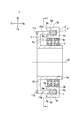
- a hollow single-phase induction motor 1 shown in FIGS. 1 and 2 includes a conductive metal stator 2, a rotor 3, and ball bearings 4 and 5.
- the rotor 3 is coaxially (center axis L0) and rotatably attached to the stator 2 by ball bearings 4 and 5.
- the stator 2 and the rotor 3 will be described in detail.
- the stator 2 shown in FIGS. 1 and 2 is formed by a case 6 and a coil 7.
- the case 6 has a bottom portion 6a, an annular outer peripheral wall 6b protruding in a direction orthogonal to the outer peripheral edge of the bottom portion 6a, and a bottom portion 6a so as to be coaxial with the outer peripheral wall 6b (center axis L0) inside the outer peripheral wall 6b. It is constituted by an annular inner peripheral wall 6c protruding from the inner peripheral edge portion, a plurality of first claw portions (8a to 8L) and a plurality of second claw portions (9a to 9L).
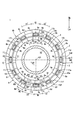
- the plurality of first claw portions (8a to 8L) shown in FIG. 3 protrude from the front end edge 6d of the outer peripheral wall 6b in the direction along the central axis L0, and are spaced apart in the circumferential direction of the front end edge 6d.
- a plurality of second claw portions (9a to 9L), which are formed, protrude in the direction along the central axis L0 from the front end edge 6e of the inner peripheral wall 6c, respectively, and surround the front end edge 6e. Twelve claw portions formed at intervals in the direction.
- the plurality of second claw portions (9a to 9L) shown in FIG. 3 are provided to face the plurality of first claw portions (8a to 8L), respectively. Both ends (8m, 8n) of the first claw portions (8a to 8L) face the opposite ends (9m, 9n) of the second claw portions (9a to 9L) facing each other in the radial direction from the central axis L0. It is formed to become one.
- the first claw portions (8a to 8g) and the first claw portions (8i to 8L) are both formed to have a uniform circumferential length W1 (
- the circumferential length W1 is the arc length of the outer circumference of each first claw portion).
- the first claw portions (8a to 8f) and the first claw portions (8i to 8L) are arranged at equal intervals of 15 °.
- the second claw portions (9a to 9f) and the second claw portions (9i to 9L) are formed so as to have a uniform circumferential length W1 ′ (the circumferential length W1 ′ is equal to each second claw portion). Arc length of the inner circumference).
- the second claw portions (9a to 9f) and the first claw portions (9i to 9L) are all arranged at equal intervals of 15 °.
- first claw portion 8g in the tip edge portion 6d shown in FIG. 3 is formed at an interval of 10 ° with respect to the first claw portion 8f and formed at an interval of 20 ° with respect to the first claw portion 8h.
- second claw portion 9g at the tip edge portion 6e is formed at an interval of 10 ° with respect to the second claw portion 9f and at an interval of 20 ° with respect to the second claw portion 9h. That is, the first claw portion 8g and the second claw portion 9h are formed at different intervals with respect to the installation interval (15 °) between the other first claw portion and the second claw portion.
- first claw portion 8h at the tip edge portion 6d shown in FIG. 3 has a circumferential length W3 (shorter than the circumferential length W1 of the other first claw portions (8a to 8g) and the first claw portions (8i to 8L)).
- the second claw portion 9h at the tip edge portion 6e is formed around the circumference of the other second claw portions (9a to 9g) and the second claw portions (9i to 9L).
- a circumferential length W3 ′ (an arc length of the outer circumference of the second claw portion 9h) shorter than the length W1 ′ is formed.
- the coil 7 is installed on the bottom portion 6a, and when a single-phase alternating current is applied, the first claw portions (8a to 8L) and the second claw portions (9a to 9L) facing the first claw portions (9a to 9L) have different magnetic poles. Generate alternately.
- the rotor 3 shown in FIGS. 1 to 3 is formed by a hollow cylindrical main body portion 3a, a flange portion 3b, a plurality of coil support portions (10a to 10L), and a plurality of rotor coils (11a to 11L).
- the main body portion 3a, the flange portion 3b, and the plurality of coil support portions (10a to 10L) are each made of a metal or resin having low conductivity, and the plurality of rotor coils (11a to 11L) are made of metal having high conductivity. It is formed.
- the flange portion 3b has a disk shape and is formed so as to protrude radially outward from the outer periphery of the front end portion of the main body portion 3a.
- Each of the plurality of coil support portions (10a to 10L) has the same rectangular parallelepiped shape, and is formed to protrude rearward along the central axis L0 from the outer peripheral end portion 3c of the flange portion 3b. Further, the plurality of coil support portions (10a to 10L) are formed at 12 locations at equal intervals of 30 ° in the circumferential direction of the flange portion 3b.
- the rotor 3 is coaxially and rotatably attached to the inner side of the inner peripheral wall 6c of the case 6 via ball bearings 4 and 5 attached to the outer periphery of the main body 3a.
- the plurality of rotor coils (11a to 11L) shown in FIGS. 1 to 3 are 12 copper members each having the same rectangular parallelepiped cylinder shape, and are fixed to the outer circumferences of the plurality of coil support portions (10a to 10L), respectively.
- the Each of the four corners of the rotor coils (11a to 11L) has an R shape. Note that the material of the rotor coil is not limited to copper as long as it is a highly conductive metal.
- the length is substantially the same as the width W4 (width in the cross section orthogonal to the central axis L0) of each rotor coil (11a to 11L).
- the rotor coils (11a to 11L) having the same shape of the rotor 3 are installed at equal intervals in the circumferential direction, whereas the first and second claw portions (8g, 9g) of the case 6 are provided. ) Are formed at different intervals with respect to the other first and second claw portions. Accordingly, the circumferential end (11m, 11n) of any one of the rotor coils (11a to 11L) (see the rotor coil 11g) has the first and second claw portions (8g, 9g) when the rotor 3 stops. ) Always stop at a position shifted in the circumferential direction with respect to both circumferential ends.
- the circumferential length W3 of the first claw portion 8h is shorter than the circumferential length W1 of the other first claw portion, and the circumferential length W3 ′ of the second claw portion 9h is larger than the circumferential length W1 ′ of the other second claw portion. short. Therefore, the inner peripheral length of the first claw portion 8h and the outer peripheral length of the second claw portion 9h of the case 6 are the circumferential end portions (11m) of any one of the rotor coils (11a to 11L) (see the rotor coil 11h). , 11n) always stops at a position shifted in the circumferential direction with respect to the circumferential end portions of both the first and second claw portions (8h, 9h) when the rotor 3 is stopped.
- the rotor coil that receives the magnetic force from the magnetic poles generated in the first and second claw portions (8g, 9g) and the first and second claw portions (8h, 9h) when energized with a single phase current An induced current for starting the rotor 3 by itself is always generated.
- the rotor coils (11a to 11L) are installed at equal intervals, and part of the first claw portions (8a to 8L) and the second claw portions (9a to 9L) are installed at different intervals.
- a part of the rotor coil (11a to 11L) is installed at different intervals, and the first claw part (8a to 8L) and the second claw part (9a to 9L) May be installed at equal intervals.
- the widths of the rotor coils (11a to 11L) are made uniform so that the peripheral lengths of the first claw portions (8a to 8L) and the second claw portions (9a to 9L) are set to other circumferences.
- the circumferential lengths of the first claw portions (8a to 8L) and the second claw portions (9a to 9L) are all formed uniformly, and then the rotor coil ( 11a to 11L) may be formed to have a width that is longer than the peripheral lengths of the first claw portions (8a to 8L) and the second claw portions (9a to 9L).
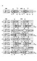
- FIG. 4 is an operation explanatory diagram of the hollow single-phase induction motor of this embodiment.
- the right figure of Fig.4 (a) is the 1st and 2nd nail
- the rotor coils (11g, 11h) are arranged in a straight line from the left in order.
- 4 (b) to 4 (i) show first claw portions (8a, 8b) and second claw portions (parts other than the starting portion of the hollow single-phase induction motor shown in FIG. 3).
- 9a, 9b) and the rotor coils (11a, 11b) are linearly arranged in order from the left, and show the change in electromagnetic force acting on the rotor coil over time.
- FIG. 4A to FIG. 4I “S” and “N” shown in the right diagrams indicate magnetic poles, and “ ⁇ ” flows from the front side of the sheet of FIG. 4 to the other side in the rotor coil.
- the direction of the induced current is indicated, and “ ⁇ ” indicates the direction of the induced current that flows from the far side to the near side in FIG. 4 in the rotor coil.
- 4A to 4I are graphs showing changes in the single-phase alternating current that is passed through the opposing coil 7.
- the horizontal axis represents time, and the vertical axis represents current intensity. Represents.
- FIGS. 4 (a) and 4 (b) are supplied with a single-phase alternating current that changes sinusoidally as shown in the left diagrams of FIGS. 4 (a) and 4 (b).
- S poles of magnetic poles are generated in the first claw portions (8a to 8L) of the case 6 shown in FIG.
- the magnetic flux passing through the rotor coils (11a to 11L) is increased by generating N poles of the magnetic poles.
- the rotor coil (11a to 11L) generates an inductive continuous flow based on Lenz's law, and the outer surface of the rotor coil (11a to 11L).
- An S pole is generated on the side 11p to prevent an increase in magnetic flux, and an N pole is generated on the inner surface 11q.
- the rotor coil (11g, 11h) has an induced current flowing away from the front side of the sheet of FIG. 3 and a second claw from the first claw portion (8a-8L). Due to the magnetic field toward the portions (9g, 9h), a starting torque P1 in the right direction of the paper based on Fleming's left hand rule (starting torque in the clockwise direction D1 around the central axis L0 in FIG. 3) is generated. As a result, the rotor 3 shown in FIGS. 1 to 3 starts relative rotation by itself with respect to the stator 2 by the starting torque P ⁇ b> 1 generated by the single-phase alternating current passed through the coil 7.
- the rotor coils (11a to 11f, 11i to 11L) shown in FIG. 3 are rotated relative to the case 6 by the starting torque P1 of the clockwise direction D1 generated in the rotor coils (11g, 11h).
- the rotor coil ( 11a to 11L) When it is arranged at a position shifted in the circumferential direction from the inside of the two claw parts, and only the other end (11n, 11n) of the circumferential end part is arranged inside the first claw part and the second claw part, the rotor coil ( 11a to 11L), a clockwise rotational torque P2 based on the left hand rule of electromagnetic induction and Fleming is generated.
- the rotor coils (11a, 11b) in FIG. 4 (c) and the rotor coils (11c-11f, 11i-11L) in FIG. 3 receive the force (rotational torque) of P1 + P2 acting in the right direction on the page. 1 to 3 rotate relative to the stator 2 by the rotational torque P1 + P2.
- the magnetic flux does not change, so that no induction power is instantaneously generated in the rotor coils (11a, 11b, 11L). (11a to 11L) further rotate in the direction D1 in FIG. 3 due to inertia while the received magnetic flux is reduced.
- a clockwise rotational torque P2 based on the left hand rule of electromagnetic induction and Fleming is generated in the rotor coils (11L, 11a) and the rotor coils (11b-11f, 11i-11k) of FIG. From FIG. 3, the rotor 3 continues to rotate in the direction D1 with respect to the stator 2 by the rotational torque P1 + P2.
- a clockwise rotational torque P2 based on the left hand rule of electromagnetic induction and Fleming is generated in the motor coils (11k, 11L) and the rotor coils (11a to 11f, 11i to 11j) of FIG. From FIG. 3, the rotor 3 continues to rotate in the direction D1 with respect to the stator 2 by the rotational torque P1 + P2.
- the rotor 3 in FIG. 3 is self-powered by the single-phase alternating current supplied to the coil 7 by the first claw portions (8g, 8h) and the second claw portions (9g, 9h) constituting the starting portion.
- the stator 2 rotates.
- the magnetic field is generated between the first claw portions (8a to 8L) and the second claw portions (9g, 9h) arranged in a ring shape and does not pass through the rotation center of the motor.
- the motor can have a hollow structure, and another mechanism or the like can be disposed inside the motor. Further, each of the rotor coils (11a to 11L) forms an extremely short conductive path in a ring shape, so that the resistance value of the conductive path becomes small. Therefore, the hollow single-phase induction motor of this embodiment can be started and rotated with a low current.
Landscapes
- Engineering & Computer Science (AREA)
- Power Engineering (AREA)
- Iron Core Of Rotating Electric Machines (AREA)
- Synchronous Machinery (AREA)
- Windings For Motors And Generators (AREA)
- Induction Machinery (AREA)
Abstract
Description
2 固定子
3 ローター
6 ケース
6a 底部
6b 外周壁
6c 内周壁
6d 外周壁の先端縁部
6e 内周壁の先端縁部
7 コイル
8a~8L 複数の第1爪部
8h 外周壁の周方向に異なる間隔で配置された第1爪部
8g 他の第1爪部より短く形成された第1爪部
9a~9L 複数の第2爪部
9h 内周壁の周方向に異なる間隔で配置された第2爪部
9g 他の第2爪部より短く形成された第2爪部
10a~10L コイル支持部
11a~11L 複数のローターコイル
L0 ローターの回動中心軸線
Claims (4)
- 交流電源によって複数の磁極を形成される金属製の固定子と、前記固定子と同軸に配置され前記固定子の磁極の変化に基づいて前記固定子に対して相対回転するローターと、を有する誘導モータにおいて、
前記固定子は、
底部と、前記底部から直交する方向に突出する円環状の外周壁と、前記外周壁の内側で前記外周壁と同軸に位置するように前記底部から突出する円環状の内周壁と、前記外周壁の先端縁部に周方向の間隔を開けて形成される複数の第1爪部と、第1爪部にそれぞれ対向するように前記内周壁の先端縁部に周方向の間隔を開けて形成される複数の第2爪部と、を有する円環形状のケースと、
前記ケースの内側に固定され、交流かつ単相の電流を通電されることで第1爪部と第2爪部に互いに異なる磁極を形成するコイルと、を有し、
前記ローターは、
前記ケースの内側に同軸かつ回転可能に支持される筒状の本体部と、
前記本体部の外周に突出形成されるフランジ部と、
前記フランジ部の外周縁部に周方向の間隔を開けて複数形成され、それぞれの先端が前記第1爪部及び第2爪部の双方と平行になるよう前記第1爪部及び第2爪部の間に形成される隙間に挿入され、かつ少なくとも1つが前記第1爪部及び第2爪部の双方に対して前記ケースの周方向にずれて配置される複数のコイル支持部と、
各コイル支持部の外周にそれぞれ取り付けられた円環形状の複数のローターコイルと、
を有することを特徴とする、中空単相誘導モータ。 - 前記第1爪部及び前記第1爪部に対向する前記第2爪部の複数の組み合わせ、または複数のコイル支持部のうち一方が前記ケースの周方向に等間隔で配置され、もう一方の少なくとも一部が前記ケースの周方向に異なる間隔で配置されたことを特徴とする、請求項1に記載の中空単相誘導モータ。
- 複数の前記第1爪部のそれぞれの内周長及び複数の前記第2爪部のそれぞれの外周長が、いずれも前記ローターコイルのそれぞれの幅よりも短く形成されたことを特徴とする、請求項1または2に記載の中空単相誘導モータ。
- 前記ローターコイルが銅製であることを特徴する、請求項1または2に記載の中空単相誘導モータ。
Priority Applications (5)
| Application Number | Priority Date | Filing Date | Title |
|---|---|---|---|
| PCT/JP2016/057432 WO2017154147A1 (ja) | 2016-03-09 | 2016-03-09 | 中空単相誘導モータ |
| CN201680077942.7A CN108432094B (zh) | 2016-03-09 | 2016-03-09 | 中空单相感应电动机 |
| JP2018503926A JP6609368B2 (ja) | 2016-03-09 | 2016-03-09 | 中空単相誘導モータ |
| EP16893479.2A EP3429062A4 (en) | 2016-03-09 | 2016-03-09 | HOLY ONE-PHASE INDUCTION MOTOR |
| US16/124,214 US10804780B2 (en) | 2016-03-09 | 2018-09-07 | Hollow single-phase induction motor |
Applications Claiming Priority (1)
| Application Number | Priority Date | Filing Date | Title |
|---|---|---|---|
| PCT/JP2016/057432 WO2017154147A1 (ja) | 2016-03-09 | 2016-03-09 | 中空単相誘導モータ |
Related Child Applications (1)
| Application Number | Title | Priority Date | Filing Date |
|---|---|---|---|
| US16/124,214 Continuation-In-Part US10804780B2 (en) | 2016-03-09 | 2018-09-07 | Hollow single-phase induction motor |
Publications (1)
| Publication Number | Publication Date |
|---|---|
| WO2017154147A1 true WO2017154147A1 (ja) | 2017-09-14 |
Family
ID=59789327
Family Applications (1)
| Application Number | Title | Priority Date | Filing Date |
|---|---|---|---|
| PCT/JP2016/057432 Ceased WO2017154147A1 (ja) | 2016-03-09 | 2016-03-09 | 中空単相誘導モータ |
Country Status (5)
| Country | Link |
|---|---|
| US (1) | US10804780B2 (ja) |
| EP (1) | EP3429062A4 (ja) |
| JP (1) | JP6609368B2 (ja) |
| CN (1) | CN108432094B (ja) |
| WO (1) | WO2017154147A1 (ja) |
Families Citing this family (3)
| Publication number | Priority date | Publication date | Assignee | Title |
|---|---|---|---|---|
| CN109713864A (zh) | 2019-03-08 | 2019-05-03 | 关伟伟 | 一种电流主控电动机 |
| CN112769306A (zh) * | 2021-01-20 | 2021-05-07 | 深圳市万至达电机制造有限公司 | 一种高功率密度的步进电机 |
| US20220243655A1 (en) * | 2021-02-03 | 2022-08-04 | The Suppes Family Trust | Flat plate airfoil platfform vehicle |
Citations (4)
| Publication number | Priority date | Publication date | Assignee | Title |
|---|---|---|---|---|
| WO2010035318A1 (ja) * | 2008-09-25 | 2010-04-01 | Takahashi Sachio | 回転機構、シングルドライブリニアモータ、電動機、車輪及び車両 |
| US20120242184A1 (en) * | 2009-09-09 | 2012-09-27 | HOBA International (Motor) Group Ltd. | Non-360 Degree Driving Brushless DC Motor |
| JP2015104250A (ja) * | 2013-11-26 | 2015-06-04 | アスモ株式会社 | モータ |
| JP2015154555A (ja) * | 2014-02-13 | 2015-08-24 | アスモ株式会社 | モータ |
Family Cites Families (26)
| Publication number | Priority date | Publication date | Assignee | Title |
|---|---|---|---|---|
| GB375721A (en) * | 1931-01-16 | 1932-06-30 | Gen Electric | Improvements in and relating to electric motors |
| US3261998A (en) * | 1960-08-12 | 1966-07-19 | Aerojet General Co | Axial airgap dynamoelectric machine |
| US3330975A (en) * | 1964-10-15 | 1967-07-11 | Vega Prec Lab Inc | Self-starting synchronous motor |
| GB1185998A (en) * | 1966-04-18 | 1970-04-02 | Gaston Cartier | D.C. Electric motors of small axial dimensions |
| DE2201145A1 (de) * | 1972-01-11 | 1973-07-19 | Hoesch Werke Ag | Antrieb fuer eine drehverbindung |
| US4080724A (en) * | 1976-01-13 | 1978-03-28 | Zephyr Wind Dynamo Company | Method of forming electrical machine care from E-laminations |
| DE3504681A1 (de) * | 1985-02-12 | 1986-09-04 | Deutsche Forschungs- und Versuchsanstalt für Luft- und Raumfahrt e.V., 5000 Köln | Antriebs- und positioniersystem |
| US4731554A (en) * | 1985-11-14 | 1988-03-15 | Allied Corporation | Low profile ring-shaped motor |
| US4949000A (en) * | 1988-07-18 | 1990-08-14 | Mueller And Smith, Lpa | D.C. motor |
| US4837474A (en) * | 1988-08-12 | 1989-06-06 | Camatec Corporation | D.C. motor |
| US5177392A (en) * | 1991-01-14 | 1993-01-05 | Westinghouse Electric Corp. | High efficiency, low reactance disk-type machine including an improved rotor and stator |
| JP3147920B2 (ja) * | 1991-04-02 | 2001-03-19 | 亮拿 佐藤 | 低電圧モータ |
| JPH08242572A (ja) * | 1995-02-28 | 1996-09-17 | Japan Servo Co Ltd | 3相永久磁石式回転電機 |
| JP3579642B2 (ja) * | 2000-12-20 | 2004-10-20 | 台達電子工業股▲ふん▼有限公司 | モータ構造 |
| US6097124A (en) * | 1997-10-23 | 2000-08-01 | Satcon Technology Corporation | Hybrid permanent magnet/homopolar generator and motor |
| US6465916B2 (en) * | 1998-12-04 | 2002-10-15 | Canon Kabushiki Kaisha | Motor |
| JP2000262038A (ja) * | 1999-03-09 | 2000-09-22 | Cateye Co Ltd | エルゴメータの負荷装置 |
| SI20497B (sl) * | 2000-01-14 | 2008-08-31 | Harmonic Drive Systems | Sinhronski hibridni elektriäśni stroj s toroidnim navitjem |
| US6891302B1 (en) * | 2000-09-23 | 2005-05-10 | Christopher W. Gabrys | Light-weight high-power electrical machine |
| JP4158024B2 (ja) * | 2002-04-30 | 2008-10-01 | 株式会社富士通ゼネラル | 誘導電動機 |
| JP4457777B2 (ja) * | 2004-06-28 | 2010-04-28 | 日産自動車株式会社 | 回転電機 |
| US8760029B2 (en) * | 2008-10-06 | 2014-06-24 | Hitachi, Ltd. | Stator core arrangements using heat-shrinkable tubing, for rotarty electric machines |
| RU2396675C1 (ru) * | 2008-12-29 | 2010-08-10 | Андрей Михайлович Максимов | Электрическая машина |
| CN102570760A (zh) * | 2011-12-19 | 2012-07-11 | 上海电机学院 | 电励磁无刷爪极电机 |
| US9667112B2 (en) * | 2014-08-28 | 2017-05-30 | General Electric Company | Rotor slot liners |
| JP2016111842A (ja) * | 2014-12-08 | 2016-06-20 | 株式会社デンソー | ダブルステータ型回転電機 |
-
2016
- 2016-03-09 JP JP2018503926A patent/JP6609368B2/ja not_active Expired - Fee Related
- 2016-03-09 CN CN201680077942.7A patent/CN108432094B/zh not_active Expired - Fee Related
- 2016-03-09 EP EP16893479.2A patent/EP3429062A4/en not_active Withdrawn
- 2016-03-09 WO PCT/JP2016/057432 patent/WO2017154147A1/ja not_active Ceased
-
2018
- 2018-09-07 US US16/124,214 patent/US10804780B2/en not_active Expired - Fee Related
Patent Citations (4)
| Publication number | Priority date | Publication date | Assignee | Title |
|---|---|---|---|---|
| WO2010035318A1 (ja) * | 2008-09-25 | 2010-04-01 | Takahashi Sachio | 回転機構、シングルドライブリニアモータ、電動機、車輪及び車両 |
| US20120242184A1 (en) * | 2009-09-09 | 2012-09-27 | HOBA International (Motor) Group Ltd. | Non-360 Degree Driving Brushless DC Motor |
| JP2015104250A (ja) * | 2013-11-26 | 2015-06-04 | アスモ株式会社 | モータ |
| JP2015154555A (ja) * | 2014-02-13 | 2015-08-24 | アスモ株式会社 | モータ |
Non-Patent Citations (1)
| Title |
|---|
| See also references of EP3429062A4 * |
Also Published As
| Publication number | Publication date |
|---|---|
| CN108432094B (zh) | 2020-08-28 |
| JPWO2017154147A1 (ja) | 2019-01-10 |
| US20190081541A1 (en) | 2019-03-14 |
| EP3429062A1 (en) | 2019-01-16 |
| CN108432094A (zh) | 2018-08-21 |
| JP6609368B2 (ja) | 2019-11-20 |
| EP3429062A4 (en) | 2019-11-27 |
| US10804780B2 (en) | 2020-10-13 |
Similar Documents
| Publication | Publication Date | Title |
|---|---|---|
| JP6284694B2 (ja) | 台所器具 | |
| CN110268610B (zh) | 具有磁旋转场降低和通量集中的同步电机 | |
| US11152828B2 (en) | Rotating electric machine | |
| KR20160131945A (ko) | 단상 외부-회전자 모터 및 그의 회전자 | |
| JP2010098945A (ja) | 発電機 | |
| JP3207654U (ja) | 単相永久磁石モータ | |
| WO2018180721A1 (ja) | 電動モータ | |
| JP4082445B2 (ja) | 電子的に切替えられる二相のリラクタンス機械 | |
| EP3308457A1 (en) | Mirroring of high rotor pole switched reluctance machines | |
| US3433987A (en) | Rotor without sticking moment | |
| US20180069462A1 (en) | Stepping Motor | |
| JP6609368B2 (ja) | 中空単相誘導モータ | |
| US11336163B2 (en) | Low profile axial, flux permanent magnet synchronous motor | |
| JP6895909B2 (ja) | ハイブリッド界磁式ダブルギャップ同期機 | |
| JP2005020885A (ja) | ロータリ・リニア直流モータ | |
| JP2019154140A (ja) | 回転電機 | |
| JP2018148675A (ja) | 回転電機のステータ | |
| WO2011036723A1 (ja) | 同期発電機 | |
| WO2021065462A1 (ja) | 回転電機 | |
| JP5924913B2 (ja) | 発電機 | |
| JP5340332B2 (ja) | 回転電機 | |
| JP2010284028A (ja) | スイッチング素子一体型回転電機 | |
| TW202537196A (zh) | 同極向量轉動馬達 | |
| WO2026018737A1 (ja) | モータ | |
| WO2021019703A1 (ja) | 三相交流発電機 |
Legal Events
| Date | Code | Title | Description |
|---|---|---|---|
| ENP | Entry into the national phase |
Ref document number: 2018503926 Country of ref document: JP Kind code of ref document: A |
|
| NENP | Non-entry into the national phase |
Ref country code: DE |
|
| WWE | Wipo information: entry into national phase |
Ref document number: 2016893479 Country of ref document: EP |
|
| ENP | Entry into the national phase |
Ref document number: 2016893479 Country of ref document: EP Effective date: 20181009 |
|
| 121 | Ep: the epo has been informed by wipo that ep was designated in this application |
Ref document number: 16893479 Country of ref document: EP Kind code of ref document: A1 |