WO2017154792A1 - Procédé de bombement à la presse-plieuse utilisant un mécanisme d'augmentation de force, et presse-plieuse - Google Patents
Procédé de bombement à la presse-plieuse utilisant un mécanisme d'augmentation de force, et presse-plieuse Download PDFInfo
- Publication number
- WO2017154792A1 WO2017154792A1 PCT/JP2017/008581 JP2017008581W WO2017154792A1 WO 2017154792 A1 WO2017154792 A1 WO 2017154792A1 JP 2017008581 W JP2017008581 W JP 2017008581W WO 2017154792 A1 WO2017154792 A1 WO 2017154792A1
- Authority
- WO
- WIPO (PCT)
- Prior art keywords
- press brake
- eccentric shaft
- actuator
- lower table
- crowning
- Prior art date
- Legal status (The legal status is an assumption and is not a legal conclusion. Google has not performed a legal analysis and makes no representation as to the accuracy of the status listed.)
- Ceased
Links
Images












Classifications
-
- B—PERFORMING OPERATIONS; TRANSPORTING
- B30—PRESSES
- B30B—PRESSES IN GENERAL
- B30B15/00—Details of, or accessories for, presses; Auxiliary measures in connection with pressing
- B30B15/16—Control arrangements for fluid-driven presses
- B30B15/24—Control arrangements for fluid-driven presses controlling the movement of a plurality of actuating members to maintain parallel movement of the platen or press beam
-
- B—PERFORMING OPERATIONS; TRANSPORTING
- B21—MECHANICAL METAL-WORKING WITHOUT ESSENTIALLY REMOVING MATERIAL; PUNCHING METAL
- B21D—WORKING OR PROCESSING OF SHEET METAL OR METAL TUBES, RODS OR PROFILES WITHOUT ESSENTIALLY REMOVING MATERIAL; PUNCHING METAL
- B21D5/00—Bending sheet metal along straight lines, e.g. to form simple curves
- B21D5/02—Bending sheet metal along straight lines, e.g. to form simple curves on press brakes without making use of clamping means
-
- B—PERFORMING OPERATIONS; TRANSPORTING
- B21—MECHANICAL METAL-WORKING WITHOUT ESSENTIALLY REMOVING MATERIAL; PUNCHING METAL
- B21D—WORKING OR PROCESSING OF SHEET METAL OR METAL TUBES, RODS OR PROFILES WITHOUT ESSENTIALLY REMOVING MATERIAL; PUNCHING METAL
- B21D5/00—Bending sheet metal along straight lines, e.g. to form simple curves
- B21D5/02—Bending sheet metal along straight lines, e.g. to form simple curves on press brakes without making use of clamping means
- B21D5/0272—Deflection compensating means
-
- B—PERFORMING OPERATIONS; TRANSPORTING
- B30—PRESSES
- B30B—PRESSES IN GENERAL
- B30B1/00—Presses, using a press ram, characterised by the features of the drive therefor, pressure being transmitted directly, or through simple thrust or tension members only, to the press ram or platen
- B30B1/02—Presses, using a press ram, characterised by the features of the drive therefor, pressure being transmitted directly, or through simple thrust or tension members only, to the press ram or platen by lever mechanism
- B30B1/06—Presses, using a press ram, characterised by the features of the drive therefor, pressure being transmitted directly, or through simple thrust or tension members only, to the press ram or platen by lever mechanism operated by cams, eccentrics, or cranks
-
- B—PERFORMING OPERATIONS; TRANSPORTING
- B30—PRESSES
- B30B—PRESSES IN GENERAL
- B30B1/00—Presses, using a press ram, characterised by the features of the drive therefor, pressure being transmitted directly, or through simple thrust or tension members only, to the press ram or platen
- B30B1/10—Presses, using a press ram, characterised by the features of the drive therefor, pressure being transmitted directly, or through simple thrust or tension members only, to the press ram or platen by toggle mechanism
- B30B1/14—Presses, using a press ram, characterised by the features of the drive therefor, pressure being transmitted directly, or through simple thrust or tension members only, to the press ram or platen by toggle mechanism operated by cams, eccentrics, or cranks
Definitions
- the present invention relates to a press brake crowning method and a press brake, and more specifically, when an eccentric shaft is rotated to perform crowning of a lower table, the eccentric shaft is increased by a booster mechanism (a booster mechanism).
- the present invention relates to a crowning method for rotating and crowning and a press brake.
- the press brake has C-shaped left and right side frames.
- a lower table is provided at the front lower portion of the side frame.
- An upper table facing the lower table is provided at the front upper part of the side frame so as to be movable up and down.
- a plate-like workpiece is placed and positioned on the lower mold mounted on the lower table. Then, the workpiece is bent by the cooperation of the upper and lower molds by pressurizing the workpiece with the upper mold provided in the upper table.
- the left and right ends of the lower table are fixed to the left and right side frames, and the left and right ends of the upper table are supported by the side frames so as to be movable up and down. Therefore, the central portions of the upper and lower tables tend to bend in directions away from each other due to the reaction force when the workpiece is bent. Therefore, when the workpiece is bent, the bending angle near the center of the workpiece becomes sweeter (larger) than the bending angles near the left and right ends, and the workpiece becomes a boat shape.
- Patent Documents 1 and 2 are configurations in which the output shaft and the eccentric shaft of the motor are directly connected via a coupling. Therefore, a large motor is used as the motor, and it has been desired to reduce the size of the motor in order to save energy and make the overall configuration compact.
- the present invention has been made in view of the above-described problems, and an object of the present invention is to provide a press brake crowning method and press brake capable of reducing the size and size of the actuator and saving energy. Is to provide.
- a front plate and a rear plate are provided on the front and rear of a lower table attached to the lower side of the left and right side frames in a press brake.
- a force increasing mechanism is provided between an actuator for rotating an eccentric shaft provided in a lower table and the eccentric shaft, and an output of the actuator is increased by the force increasing mechanism and transmitted to the eccentric shaft.
- a press brake crowning method is provided for performing crowning by rotating the.
- a front plate and a rear plate are arranged before and after the lower table supported by the left and right side frames in the press brake, and a plurality of the lower tables provided in the lower table are separated in the left-right direction.
- a press brake crowning method that rotates an eccentric shaft to perform crowning, and includes an intensifying mechanism between the actuator for rotating each eccentric shaft and each eccentric shaft, and outputs the actuator.
- a press brake crowning method is provided in which the force is increased by the force increasing mechanism and transmitted to each eccentric shaft, and the eccentric shaft is rotated to perform crowning.
- each of the force-increasing mechanisms extends in a direction intersecting with the axis of each of the left and right eccentric shafts, and is provided integrally with each of the eccentric shafts.
- the link member having the distal end portion pivotally coupled to the distal end portion of each lever member and the proximal end portion pivotally coupled to each link member are pushed in a direction intersecting the longitudinal direction of each link member.
- the front plate and the rear plate are arranged before and after the lower table supported by the left and right side frames in the press brake, and the eccentrics provided in the lower table are separated in the left-right direction.
- a press brake crowning method in which a shaft mechanism is rotated to perform crowning, each of which includes a force-increasing mechanism between each actuator and each eccentric shaft mechanism for individually rotating each eccentric shaft mechanism.
- a press brake crowning method is provided in which the output of each actuator is boosted by each of the booster mechanisms and transmitted to each of the eccentric shaft mechanisms, and the eccentric shaft mechanisms are individually rotated to perform crowning.
- each eccentric shaft mechanism provided separately in the left-right direction has a pair of left and right eccentric shafts rotatably, and each of the force-increasing mechanisms allows a pair of left and right When the eccentric shafts are rotated, the eccentric shafts are synchronized and rotated in opposite directions to perform crowning.
- a front plate and a rear plate are provided before and after the lower table attached to the lower side of the left and right side frames in the press brake, and in the form of a plate in cooperation with the lower mold provided in the lower table.
- An upper table having an upper mold for bending the workpiece is a press brake provided on the upper side of the left and right side frames so as to be movable up and down, and an eccentric shaft for crowning the lower table,
- a press which is provided in a lower table so as to be freely rotatable, and includes a force-increasing mechanism for increasing the output of the actuator and transmitting it to each eccentric shaft between the actuator for rotating the eccentric shaft and the eccentric shaft.
- a brake is provided.
- a front plate and a rear plate are provided before and after the lower table attached to the lower side of the left and right side frames in the press brake, and in the form of a plate in cooperation with the lower mold provided in the lower table.
- a press brake provided with an upper table having an upper mold for bending the workpiece of the workpiece on the upper side of the left and right side frames, and having left and right eccentric shafts for crowning the lower table.
- the lower table is rotatably provided in the left and right direction, and the actuator output is increased between the eccentric shaft and the actuator for rotating the eccentric shaft, and the eccentric shaft is moved to the eccentric shaft.
- a press brake having a booster mechanism for transmission is provided.
- the force-increasing mechanism is provided to extend in a direction intersecting with the axis of each of the left and right eccentric shafts, and is provided integrally with each eccentric shaft.
- tip part of each said lever member, and the base end part side by which the said link member was pivotally connected is pushed and pulled by the said actuator.
- each of the left and right eccentric shafts includes a plurality of eccentric shafts arranged in parallel in the left-right direction, and the plurality of eccentric shafts provided in parallel are synchronized in the same direction. It is the structure rotated to.
- a front plate and a rear plate are provided before and after the lower table attached to the lower side of the left and right side frames in the press brake, and in the form of a plate in cooperation with the lower mold provided in the lower table.
- a left and right eccentric shaft mechanism for crowning the lower table which is a press brake provided with an upper table having an upper mold for bending a workpiece of the workpiece on the upper side of the left and right side frames.
- each of the actuators is provided between each of the actuators provided separately and each of the eccentric shaft mechanisms in order to individually operate each of the eccentric shaft mechanisms.
- press brakes each provided with a force-increasing mechanism for increasing the output of the power and transmitting the output to the eccentric shaft mechanisms individually.
- the force-increasing mechanism is constituted by a toggle mechanism.
- the eccentric shaft mechanism includes a plurality of eccentric shafts arranged in parallel in the left-right direction, and the toggle mechanism is provided integrally with each eccentric shaft provided in parallel.
- the distal end portion of each link member is pivotally connected to the distal end portion of each lever member, and the proximal end portion pivotally connected to each other of the link members is pushed and pulled by the actuator.
- the actuator is a servo motor, and a member that pushes and pulls the pivot connecting portion of each link member is reciprocally screwed to a ball screw rotated by the servo motor. It is a ball nut.
- the ball screw is arranged in a plane parallel to the plate surface of the lower table, and a rotation axis of the servo motor is in a plane parallel to the plate surface of the lower table. It is arranged.
- a front plate and a rear plate are provided before and after the lower table attached to the lower side of the left and right side frames in the press brake, and in the form of a plate in cooperation with the lower mold provided in the lower table.
- a press brake provided with an upper table having an upper mold for bending the workpiece of the workpiece on the upper side of the left and right side frames, and having left and right eccentric shafts for crowning the lower table.
- the lower table is pivotably spaced apart in the left-right direction, and the both end sides of the telescopically movable connecting member are connected to the free end side of each intensifying link mechanism in which the base end side is connected to the left and right eccentric shafts.
- a press brake is provided in which the connecting member is provided with an actuator for extending and contracting the connecting member.
- the connecting member includes a ball screw mechanism at both ends, and an actuator that individually operates the ball screw mechanisms at both ends.
- the force-increasing link mechanism is pivotally connected to the distal end portion of each lever member having a proximal end portion coupled to each eccentric shaft provided adjacent thereto.
- one link member in each of the link members is longer than the other link member, the base end side of the other link member is pivotally connected to an intermediate position in the one link member, The end of the connecting member is connected to the base end of the one link member.
- a front plate and a rear plate are provided before and after the lower table attached to the lower side of the left and right side frames in the press brake, and in the form of a plate in cooperation with the lower mold provided in the lower table.
- a press brake provided with an upper table having an upper mold for bending the workpiece of the workpiece on the upper side of the left and right side frames, and having left and right eccentric shafts for crowning the lower table.
- the lower table is rotatably provided in the left and right direction, and the actuator output is increased between the eccentric shaft and the actuator for rotating the eccentric shafts.
- a press brake having a force-increasing mechanism for transmitting and urging means for assisting the operation of the actuator when the eccentric shaft is rotated by the actuator. It is.
- a front plate and a rear plate are provided before and after the lower table attached to the lower side of the left and right side frames in the press brake, and in the form of a plate in cooperation with the lower mold provided in the lower table.
- a press brake provided with an upper table having an upper mold for bending the workpiece of the workpiece on the upper side of the left and right side frames, and having left and right eccentric shafts for crowning the lower table.
- the lower table is pivotably spaced apart in the left-right direction, and the both end sides of the extendable connecting member are connected to the free end side of each intensifying link mechanism in which the base end side is connected to the left and right eccentric shafts.
- a press brake is provided which includes a biasing means for assisting the operation of each actuator.
- a front plate and a rear plate are provided before and after the lower table attached to the lower side of the left and right side frames in the press brake, and in the form of a plate in cooperation with the lower mold provided in the lower table.
- a press brake provided with an upper table having an upper mold for bending the workpiece of the workpiece on the upper side of the left and right side frames, and having left and right eccentric shafts for crowning the lower table.
- the lower table is pivotably spaced apart in the left-right direction, and the both end sides of the extendable connecting member are connected to the free end side of each intensifying link mechanism in which the base end side is connected to the left and right eccentric shafts.
- the connecting member is provided with an actuator for rotating a ball screw mechanism provided in the connecting member, and the force-increasing links are provided by the actuator via the connecting member.
- the press brake biasing means for assisting the operation of the actuator is provided in each energizing link mechanism is provided.
- the urging means is a compression spring.
- the output of the actuator is increased by interposing the force increasing mechanism between the actuator for rotating the eccentric shaft and the eccentric shaft. Then communicate. Therefore, it is possible to provide a press brake crowning method and a press brake that can reduce the size and size of the actuator and can save energy.
- FIG. 10 is a perspective view of the toggle mechanism shown in FIG. 9.
- FIG. 10 is a cross-sectional plan view of the toggle mechanism shown in FIG. 9.
- FIG. 10 is a plan view of the toggle mechanism shown in FIG. 9.
- FIG. 1 It is a rear view which shows the structure of a toggle mechanism part. It is a back perspective view which shows the structure of the lower table which concerns on 6th Embodiment. It is a rear view which shows the structure of the toggle mechanism shown in FIG. It is a rear view which shows the operation state of the toggle mechanism shown in FIG. It is a rear view which shows the operation state of the toggle mechanism shown in FIG. It is a rear view which shows the structure of the lower table which concerns on 7th Embodiment.
- the structure of the lower table which concerns on 7th Embodiment is shown, (a) is a top view, (b) is a rear view. It is a rear view which shows the operation state of a toggle mechanism. It is a rear view which shows the operation state of a toggle mechanism.
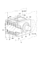
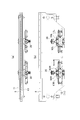
- a press brake 1 includes C-shaped left and right side frames 3L and 3R on both sides in the left-right direction (X-axis direction).
- the left and right ends of the plate-like lower table 5 are supported on the lower portions on the front side of the side frames 3L, 3R.
- the left and right ends of the upper table 7 as a ram are supported on the front upper portions of the side frames 3L and 3R so as to be movable up and down.
- ram lifting and lowering operation devices 9L and 9R each composed of, for example, a hydraulic cylinder or a ball screw mechanism are mounted on the front upper portions of the side frames 3L and 3R.
- a plate-like workpiece is placed and positioned on a lower mold (not shown) mounted on the lower table 5. Then, by lowering the upper table 7, the work is pressurized with an upper mold (not shown) mounted on the upper table 7. In this way, when the workpiece is pressed, the workpiece is bent by the cooperation of the upper and lower molds.
- the central portions in the left and right directions of the upper and lower tables 7 and 5 are separated from each other by the reaction force. Tend to curve. Therefore, in order to keep the upper and lower molds mounted on the upper and lower tables 7 and 5 in a parallel state and bend the workpiece, the central portion in the left and right direction of the lower table 5 is curved in a convex shape upward. Crowning is performed.
- the lower table 5 is attached to the lower front side of the side frames 3L, 3R via bolts (not shown).
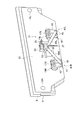
- a front plate 11 and a rear plate 13 are provided before and after the lower table 5, respectively.
- the front plate 11, the lower table 5, and the rear plate 13 are integrally provided via left and right pivots 15L and 15R penetrating the front plate 11 in the front-rear direction.
- 17L and 17R are formed.
- Units (eccentric shaft mechanisms) 19L and 19R are internally provided.
- the eccentric shaft units 19L and 19R have front and rear bearing blocks whose movement in the vertical direction is restricted in the through holes 17L and 17R in the front plate 11 and the rear plate 13, respectively.
- 21F and 21B are provided apart from each other in the front-rear direction.
- the plate thickness of the front and rear bearing blocks 21F and 21B is substantially equal to the plate thickness of the front plate 11 and the rear plate 13.
- the front-rear direction interval is substantially equal to the front-rear direction interval between the front plate 11 and the rear plate 13.
- Front and rear ends of a pair of left and right eccentric shafts 23 having the same configuration are rotatably supported on the bearing blocks 21F and 21B.
- the bearing blocks 21F and 21B are each provided with a bearing flange 25, and the front and rear ends of the eccentric shaft 23 are rotatably supported by the bearing flange 25. Between the front and rear bearing flanges 25, the eccentric shaft 23 is provided with a large-diameter eccentric portion 23E. A lift block 29 is supported on the eccentric portion 23E via a plurality of bearings 27.
- the elevating block 29 is disposed between the front and rear bearing blocks 21F and 21B so as to be movable up and down.
- a pressing plate 29 ⁇ / b> A that presses the upper surface of the through holes 17 ⁇ / b> L and 17 ⁇ / b> R formed in the lower table 5 is provided on the upper surface of the elevating block 29.
- the lifting block 29 is restricted from turning so as not to follow when the eccentric shaft 23 is turned.
- each eccentric shaft 23 can be made thinner compared to the case where a single eccentric shaft is used, and the vertical dimension can be suppressed to achieve compactness.
- the left and right eccentric shaft units 19L and 19R provided in the left and right through holes 17L and 17R have a symmetrical configuration and their operating directions are opposite to each other.
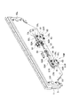
- an operating device (actuator) 31 is provided on the rear surface of the rear plate 13. More specifically, a support bracket 33 is attached to the rear surface of the rear plate 13, and a servo motor 35 is attached to the support bracket 33.
- the support bracket 33 is provided with a ball screw 37 that is rotated by the servo motor 35 vertically and rotatably.
- a nut member 39 is screwed onto the ball screw 37 so as to be movable up and down. Accordingly, when the servo motor 35 is rotated forward and backward, the ball screw 37 is rotated forward and backward, and the nut member 39 is moved up and down.
- boosting mechanisms (boost mechanisms) 41L and 41R are provided between the operating device 31 and the eccentric shafts 23, respectively. Yes.
- the force-increasing mechanism 41 has a function of increasing the output of the operating device 31 and transmitting it to the eccentric shafts 23.
- the force-increasing mechanism 41 is constituted by a toggle mechanism. It is configured.
- the tip portions of the left and right link members 49L, 49R are pivotally connected to the hinge pins 45 of the left and right force-increasing mechanisms 41L, 41R.
- the base end portions of the left and right link members 49L and 49R are pivotally connected to each other via a pivot 51.
- a push-pull member 53 that pushes and pulls the pivot 51 in the upward direction, that is, the direction intersecting the longitudinal direction of the link members 49L and 49R is pivotally attached to the pivot 51. As shown in FIG. 2, the push-pull member 53 is attached to the nut member 39 in the operating device 31 as an example of an actuator.
- the push-pull member 53 is integrally moved up and down.
- the depression angles of the link members 49L and 49R of the left and right link members 49L and 49R are gradually increased.
- the distal end portions of the lever members 43 in the left and right eccentric shaft units 19L and 19R are pressed and rotated outwardly, in other words, the distal end portions of the lever members 43 are separated from each other.
- each eccentric shaft 23E in each eccentric shaft 23 is gradually raised from the lowered position. Therefore, the pressing plate 29A provided in each lifting block 29 in the left and right eccentric shaft units 19L and 19R presses the lower table 5 upward to perform crowning.
- the eccentric shafts 23 are rotated to perform crowning, the eccentric shafts 23 are rotated via the force-increasing mechanisms 41L and 41R configured by a toggle mechanism. Therefore, when the eccentric shaft 23 is rotated, the output of the operating device 31 is increased to rotate. Therefore, the operating device 41 can be reduced in size and size.
- the operating device (actuator) for moving the push-pull member 53 up and down (push-pull) is not limited to the above-described configuration, and a fluid pressure cylinder or the like can be used, for example.
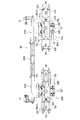
- left and right eccentric shaft units 55L and 55R corresponding to the left and right eccentric shaft units 19L and 19R described above are housed in the through holes 17L and 17R in the same manner as the eccentric shaft units 19L and 19R. .
- the eccentric shaft units 55L and 55R are provided with left and right eccentric shafts 57L and 57R corresponding to the eccentric shaft 23, respectively.
- the eccentric shafts 57L and 57R are configured to be bilaterally symmetric and are configured to rotate in opposite directions to each other, which is different from the configuration of the eccentric shaft units 19L and 19R described above. However, since the other configurations are the same and have the same functions, the detailed description of the eccentric shaft units 55L and 55R is omitted.
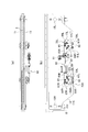
- the base ends of the left and right lever members 59L and 59R corresponding to the lever member 43 are integrally attached to the eccentric shafts 57L and 57R provided in the left and right eccentric shaft units 55L and 55R. Further, the distal ends of the link members 61L and 61R corresponding to the link members 49L and 49R are pivotally connected to the distal ends of the lever members 59L and 59R via hinge pins 63, respectively. The base ends of the link members 61L and 61R are pivotally connected to the push / pull member 67 via a pivot 65. The push / pull member 67 corresponds to the push / pull member 53 described above.
- the structure of the actuator (actuator) 69 that moves the push-pull member 67 up and down is the same as that of the actuator 31 described above, the same reference numerals are given to the constituent elements having the same function, and the description is repeated. Is omitted.
- the nut member 39 and the push / pull member 67 are integrally connected via a connecting rod 71.
- the lever members 59L and 59R and the link members 61L and 61R for rotating the pair of left and right eccentric shafts 57L and 57R in the left and right eccentric shaft units 55L and 55R are toggle mechanisms 73L as an example of a force-increasing mechanism. , 73R. Therefore, when the servo motor 35 in the left and right actuators 69 is driven to rotate the ball screw 37 forward and backward, the nut member 39 is moved up and down. Therefore, the link members 61L and 61R are pushed and pulled through the push / pull member 67.
- the depression angle between the link members 61L and 61R gradually increases. Therefore, the output of the servo motor 35 is transmitted from the ball screw 37 and the nut member 39 to the eccentric shafts 57L and 57R via the toggle mechanisms 73L and 73R. That is, the output of the servo motor 35 is increased and transmitted to the eccentric shafts 57L and 57R. Therefore, the servo motor 35 can be reduced in size and size.
- an operating device 69 for operating the left and right eccentric shaft units 55L and 55R is individually provided. Therefore, the left and right eccentric shaft units 55L and 55R can be individually operated. That is, the left and right crowning in the lower table 5 can be performed individually.
- this invention is not limited only to embodiment mentioned above, It can implement with another form by making an appropriate change.
- the eccentric shaft is provided with, for example, a large-diameter sector gear, and the sector gear is rotated by a small-diameter gear, or the sector gear is configured as a worm gear.
- the sector gear is configured as a worm gear.
- the configuration of the boosting mechanism may be configured to rotate the eccentric shaft via a lever crank mechanism using a “lever”, for example.
- the place where the actuator is provided is not limited to the rear plate, but may be a front plate. Further, it may be a part of a frame such as the left and right side frames.
- FIG. 6 shows a configuration of a boosting (boost) mechanism according to the third embodiment for rotating the eccentric shaft provided in the eccentric shaft unit.
- boost boost
- eccentric shaft units 55L and 55R are arranged in through holes 17L and 17R formed in the front plate 11, the lower table 5, and the rear plate 13, respectively.
- the left and right eccentric shafts 57L and 57R (see FIG. 7B) provided in the eccentric shaft units 55L and 55R are provided with lever members 59L that constitute a part of the long toggle mechanisms 73L and 73R that are force-increasing link mechanisms. , 59R are attached integrally.
- link members 61L and 61R are pivotally connected to the distal ends of the lever members 59L and 59R via the hinge pins 63.
- one link member 61R is configured to be longer than the other link member 61L.
- the base end portion of the other link member 61L is pivotally connected to an intermediate position of the one link member 61R via a pivot shaft 81.
- the lever members 59L and 59R and the link members 61L and 61R constitute an intensifying link mechanism (toggle mechanisms 73L and 73R).
- both ends of a telescopic connecting member 83 for rotating the eccentric shafts 57L and 57R via the force-increasing link mechanism are provided at the distal end portions (free end portions) of the left and right link members 61R in the left and right force-increasing link mechanisms.
- the parts are pivotally connected via a pivot 85.
- the connecting member 83 is divided into a first connecting portion 83A having a ball screw 87 rotatably and a second connecting portion 83B having a ball nut 89 screwed to the ball screw 87.
- the first connecting portion 83A is provided with a servo motor 91 for rotating the ball screw 87.
- the overall length of the connecting member 83 can be adjusted by rotating the servo motor 91 and adjusting the screwed state of the ball screw 87 and the ball nut 89. Therefore, the eccentric shafts 57L and 57R in the left and right eccentric shaft units 55L and 55R can be rotated by the servo motor 91. That is, it is possible to adjust the crowning of the lower table 5 by driving the left and right eccentric shaft units 55L and 55R.
- FIG. 8 shows a fourth embodiment for rotating the eccentric shaft provided in the eccentric shaft unit.
- the connecting member 83 for operating the left and right eccentric shaft units 55L and 55R via the left and right toggle mechanisms 73L and 73R is divided into three parts.
- the end portions of the first connecting member 83A including the ball screw 87 are pivotally connected to the link member 61R in the toggle mechanisms 73L and 73R.
- the 2nd connection part 83B provided with the ball nut 89 screwed together with the said ball screw 87 at both ends is arrange
- the connecting member 83 can be expanded and contracted by rotationally driving the ball screw 87 by the servo motor 91 provided in each of the first connecting portions 83A on both sides. Therefore, the eccentric shafts provided in the left and right eccentric shaft units 55L and 55R can be rotated to crown the lower table 5.
- the servo motor 91 since the servo motor 91 is provided, the servo motor 91 can be downsized.
- the connection member 83 it is also possible to use the fluid pressure cylinder which can be expanded / contracted, for example instead of the ball screw mechanism mentioned above.
- FIG. 9 shows a fifth embodiment.
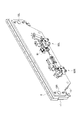
- the left and right eccentric shaft units 55L and 55R provided in the left and right through holes 17L and 17R formed in communication with the front plate 11, the lower table 5 and the rear plate 13 are connected to the left and right toggles. It is the structure which act
- the eccentric shaft unit 55L operated by the toggle mechanism 93L is provided with left and right eccentric shafts 57L and 57R (see FIG. 11).
- the eccentric shafts 57L and 57R have lever members 59L and 59R.
- the base end of is attached.
- the front ends of the lever members 59L and 59R are pivotally connected to the front ends of the T-shaped link members 95L and 95R via hinge pins 63 (see FIG. 13).
- the base ends of the link members 95L and 95R are pivotally connected to the push / pull member 67 via the pivot 65.
- the push / pull member 67 is moved up and down by a servo motor 35 attached to the rear plate 13. That is, the servo motor 35 is supported by a support bracket 33 attached to the rear surface of the rear plate 13. A ball screw 37 rotated by a servo motor 35 is supported on the support bracket 33 vertically and rotatably. A nut member 39 integrally connected to the push-pull member 67 is screwed to the ball screw 37 so as to be movable up and down.
- the push-pull member 67 is moved up and down via the nut member 39 by rotating the ball screw 37 forward and backward by the servo motor 35. Therefore, the eccentric shafts 57L and 57R in the eccentric shaft unit 55L are rotated via the toggle mechanism 93L including the link members 95L and 95R and the lever members 59L and 59R.
- the eccentric shafts 57L and 57R are rotated by the servo motor 35 as an actuator.
- the biasing means for assisting the operation of the servo motor 35 is provided when the eccentric shafts 57L and 57R are rotated by the servo motor 35.
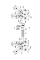
- end plates 99 are provided on the lateral sides of the link members 95L and 95R.
- the end plate 99 is integrally provided at both ends of a plurality of guide rods 97 that are long in the left-right direction.
- a left and right L-shaped slide plate 101 having a left and right cross section that is movable toward and away from each other is movably supported at an intermediate position in the left and right direction of the guide rod 97.
- the distal ends of the arm portions 95LA and 95RA provided in the link members 95L and 95R are pivotally connected to the left and right slide plates 101 via a pivot shaft 102.
- the arm portions 95LA and 95RA are provided so as to protrude in a direction intersecting the longitudinal direction of the link members 95L and 95R. Accordingly, the link members 95L and 95R are T-shaped.
- a plurality of coil springs 103 are mounted between the end plate 99 and the slide plate 101.
- the coil spring 103 constitutes an urging means that assists the operation of the servo motor 35. That is, the coil spring 103 is compressed and always functions in a direction in which the left and right slide plates 101 approach each other.
- the seat plate 105 (see FIG. 13) is provided in each of the hinge pins 63 described above. Between the seat plates 105, a plurality of coil springs 107 as urging means are mounted.
- the coil springs 103 and 107 as urging means assist the drive of the servo motor 35 when the lower table 5 is crowned. Therefore, the servo motor 35 can be reduced in size and energy can be saved.
- the left and right eccentric shaft units 55L and 55R can be individually operated. Therefore, when changing the position of the lower table 5 in the left-right direction and performing step bending of the workpiece, the lower table 5 can be crowned corresponding to each bending position.
- FIG. 14 shows a sixth embodiment.
- This embodiment corresponds to a combination of the above-described embodiment shown in FIGS. 9 to 13 and the embodiment of the connecting member 83 in the embodiment shown in FIG. Therefore, the duplicate description is abbreviate
- the left and right toggle mechanisms 93L and 93R are interlocked. That is, in the sixth embodiment, the servo motor 35 in the embodiment shown in FIG. 9 is omitted. Then, in the link member 95L in the toggle mechanisms 93L and 93R, as shown in FIG. 15, the arm portion 95LA is formed so as to largely protrude upward from the pivot 102 portion. In the above configuration, the left and right arm portions 95LA are provided with the connecting member 83 according to the embodiment shown in FIG.
- the plurality of coil springs 103 and 107 assist the operation of the servo motor 91, and the same effect as described above can be obtained.
- the left and right toggle mechanisms 93L and 93R are provided with coil springs as biasing means, and the left and right toggle mechanisms 93L and 93R are interlocked by a single servo motor.
- the toggle mechanisms 93L and 93R have lever members 59L and 59R attached to the eccentric shafts 57L and 57R in the left and right eccentric shaft units 55L and 55R (see FIG. 21), similarly to the configuration described above.
- Link members 61L and 61R are pivotally connected to the lever members 59L and 59R via hinge pins 63, respectively.
- the link members 61L and 61R are pivotally connected via a pivot 65.
- toggle mechanisms 93L and 93R are configured by the lever members 59L and 59R and the link members 61L and 61R.
- both toggle mechanisms 93L and 93R are operated in conjunction by rotating the ball screw 87 forward and backward by the servo motor 91 provided in the connecting member 83 to expand and contract the connecting member 83. Therefore, the eccentric shafts 57L and 57R in the left and right eccentric shaft units 55L and 55R are simultaneously rotated in conjunction with each other to perform crowning.
- the urging means for assisting the rotation of the eccentric shafts 57L and 57R when performing crowning is configured as follows (see FIG. 20).
- the urging means includes urging means 109A and 109B that assist the link members 61L and 61R individually. That is, the urging means 109 ⁇ / b> A includes a seat plate 113 pivotally attached to the rear plate 13 via the pivot 111. In addition, a seat plate 117 pivotally attached to the link member 61L via the pivot 115 is provided. A coil spring 119 is mounted between the seat plates 113 and 117. The coil spring 119 acts and assists so as to press the link member 61L.
- the urging means 109B includes a seat plate 123 pivotally attached to the rear plate 13 via a pivot 121. Further, a bracket 127 pivotally attached to the link member 61R via the pivot 125 is provided. A rod 129 provided integrally with the bracket 127 penetrates the seat plate 123 slidably, and a seat plate 131 is provided at the tip of the rod 129. A coil spring 133 is mounted between the seat plate 123 and the seat plate 131.
- the biasing means 109B assists by acting so as to pull the link member 61R.
- the eccentric shaft in the press brake when the eccentric shaft in the press brake is rotated to perform crowning, the eccentric shaft is connected via a toggle mechanism as an example of a boosting mechanism (a boosting mechanism). Rotate. Therefore, the actuator for rotating the eccentric shaft can be reduced in size.
- an urging means for assisting the operation of a toggle mechanism (intensifying link mechanism) for rotating the eccentric shaft is provided. Therefore, the actuator can be further downsized due to the synergistic effect of the effect of the toggle mechanism and the effect of the urging means.
- the urging means is not limited to the coil spring as described above, and for example, a gas spring or the like can be used.
Landscapes
- Engineering & Computer Science (AREA)
- Mechanical Engineering (AREA)
- Bending Of Plates, Rods, And Pipes (AREA)
- Press Drives And Press Lines (AREA)
Abstract
L'invention concerne un procédé de bombement et une presse-plieuse dans laquelle, lors de la réalisation d'un bombement avec une table inférieure, le bombement est réalisé tout en faisant tourner des arbres excentriques à l'aide d'un mécanisme d'augmentation de force. Dans ce procédé de bombement à la presse-plieuse, une plaque avant (11) et une plaque arrière (13) sont situées respectivement à l'avant et à l'arrière d'une table inférieure (5), qui est supportée par des cadres latéraux gauche et droit (3L et 3R) dans une presse-plieuse (1), et un bombement est réalisé pendant la rotation d'arbres excentriques (23), qui sont situés dans la table inférieure (5) avec des intervalles entre ceux-ci dans les directions gauche-droite. Un mécanisme d'augmentation de force (41) est prévu entre chaque arbre excentrique (23) et un actionneur (31) pour la rotation de chaque arbre excentrique (23), la sortie de l'actionneur (31) est augmentée par le mécanisme d'augmentation de force (41) et est transmise à chaque arbre excentrique (23), et chaque arbre excentrique (23) est mis à tourner, ce qui permet de réaliser le bombement.
Priority Applications (1)
| Application Number | Priority Date | Filing Date | Title |
|---|---|---|---|
| EP17763132.2A EP3427854B1 (fr) | 2016-03-11 | 2017-03-03 | Presse-plieuse utilisant un mécanisme d'augmentation de force |
Applications Claiming Priority (4)
| Application Number | Priority Date | Filing Date | Title |
|---|---|---|---|
| JP2016047798 | 2016-03-11 | ||
| JP2016-047798 | 2016-03-11 | ||
| JP2017000111A JP6175200B1 (ja) | 2016-03-11 | 2017-01-04 | プレスブレーキのクラウニング方法及びプレスブレーキ |
| JP2017-000111 | 2017-01-04 |
Publications (1)
| Publication Number | Publication Date |
|---|---|
| WO2017154792A1 true WO2017154792A1 (fr) | 2017-09-14 |
Family
ID=59505301
Family Applications (1)
| Application Number | Title | Priority Date | Filing Date |
|---|---|---|---|
| PCT/JP2017/008581 Ceased WO2017154792A1 (fr) | 2016-03-11 | 2017-03-03 | Procédé de bombement à la presse-plieuse utilisant un mécanisme d'augmentation de force, et presse-plieuse |
Country Status (3)
| Country | Link |
|---|---|
| EP (1) | EP3427854B1 (fr) |
| JP (1) | JP6175200B1 (fr) |
| WO (1) | WO2017154792A1 (fr) |
Cited By (2)
| Publication number | Priority date | Publication date | Assignee | Title |
|---|---|---|---|---|
| CN108608480A (zh) * | 2018-04-13 | 2018-10-02 | 盐城市协和机械有限公司 | 一种裁断机的横梁升降机构及升降方法 |
| CN109848263A (zh) * | 2019-01-29 | 2019-06-07 | 廊坊中德汽车座椅制造有限公司 | 汽车座椅u型头枕骨架折弯机 |
Citations (3)
| Publication number | Priority date | Publication date | Assignee | Title |
|---|---|---|---|---|
| JPH08103832A (ja) * | 1994-10-03 | 1996-04-23 | Murata Mach Ltd | パンチ駆動装置 |
| JPH08129938A (ja) * | 1994-09-08 | 1996-05-21 | Chubu Electric Power Co Inc | 電力用開閉機器の電動式開閉操作装置 |
| JP2015178131A (ja) * | 2014-02-27 | 2015-10-08 | 株式会社アマダホールディングス | 曲げ加工装置 |
-
2017
- 2017-01-04 JP JP2017000111A patent/JP6175200B1/ja active Active
- 2017-03-03 WO PCT/JP2017/008581 patent/WO2017154792A1/fr not_active Ceased
- 2017-03-03 EP EP17763132.2A patent/EP3427854B1/fr active Active
Patent Citations (3)
| Publication number | Priority date | Publication date | Assignee | Title |
|---|---|---|---|---|
| JPH08129938A (ja) * | 1994-09-08 | 1996-05-21 | Chubu Electric Power Co Inc | 電力用開閉機器の電動式開閉操作装置 |
| JPH08103832A (ja) * | 1994-10-03 | 1996-04-23 | Murata Mach Ltd | パンチ駆動装置 |
| JP2015178131A (ja) * | 2014-02-27 | 2015-10-08 | 株式会社アマダホールディングス | 曲げ加工装置 |
Cited By (4)
| Publication number | Priority date | Publication date | Assignee | Title |
|---|---|---|---|---|
| CN108608480A (zh) * | 2018-04-13 | 2018-10-02 | 盐城市协和机械有限公司 | 一种裁断机的横梁升降机构及升降方法 |
| CN108608480B (zh) * | 2018-04-13 | 2024-02-23 | 浙江奥星工贸有限公司 | 一种裁断机的横梁升降机构及升降方法 |
| CN109848263A (zh) * | 2019-01-29 | 2019-06-07 | 廊坊中德汽车座椅制造有限公司 | 汽车座椅u型头枕骨架折弯机 |
| CN109848263B (zh) * | 2019-01-29 | 2024-04-05 | 廊坊中德汽车座椅制造有限公司 | 汽车座椅u型头枕骨架折弯机 |
Also Published As
| Publication number | Publication date |
|---|---|
| EP3427854A4 (fr) | 2019-03-27 |
| JP2017164809A (ja) | 2017-09-21 |
| JP6175200B1 (ja) | 2017-08-02 |
| EP3427854B1 (fr) | 2021-06-16 |
| EP3427854A1 (fr) | 2019-01-16 |
Similar Documents
| Publication | Publication Date | Title |
|---|---|---|
| CN101561022B (zh) | 铁道车辆用盘式制动装置 | |
| US9688041B2 (en) | Drive device for a bending press | |
| JP3850934B2 (ja) | ラム昇降駆動装置及びプレス機械 | |
| US7165437B2 (en) | Mechanical press device | |
| JP2008043970A (ja) | サーボプレスとその運転方法 | |
| JP6175200B1 (ja) | プレスブレーキのクラウニング方法及びプレスブレーキ | |
| JP6123810B2 (ja) | 鍛造金型の複動システム | |
| CN101239505A (zh) | 多连杆液压压力机 | |
| JP6415529B2 (ja) | 成形プレス機 | |
| CN110743998A (zh) | 一种混合驱动冲压机 | |
| CA2947359C (fr) | Presse a articulation | |
| CN113441671B (zh) | 汽车五金件生产用锻压定位工装 | |
| JP2010042426A (ja) | プレス機械のスライド構造 | |
| CN110355249A (zh) | 一种丝杠驱动双肘杆机构的伺服包边压力机 | |
| JP4979501B2 (ja) | コンロッドレスプレス | |
| CN112475071A (zh) | 零件两端部同步扩口装置 | |
| CN224087643U (zh) | 一种折弯机 | |
| CN223465435U (zh) | 一种液压成型设备 | |
| JP2018094583A (ja) | ノックアウト装置、およびプレス装置。 | |
| CN224128383U (zh) | 一种具有定位机构的汽车齿轮锻件加工用冲孔模具 | |
| CN215469179U (zh) | 一种增力压紧机构 | |
| CN222679441U (zh) | 一种锻压机滑块升降调节装置 | |
| CN223960357U (zh) | 一种用于零部件加工的可调节式折弯结构 | |
| CN215508477U (zh) | 一种中置机构 | |
| CN221067256U (zh) | 一种节能型液压机 |
Legal Events
| Date | Code | Title | Description |
|---|---|---|---|
| NENP | Non-entry into the national phase |
Ref country code: DE |
|
| WWE | Wipo information: entry into national phase |
Ref document number: 2017763132 Country of ref document: EP |
|
| ENP | Entry into the national phase |
Ref document number: 2017763132 Country of ref document: EP Effective date: 20181011 |
|
| 121 | Ep: the epo has been informed by wipo that ep was designated in this application |
Ref document number: 17763132 Country of ref document: EP Kind code of ref document: A1 |