WO2017155002A1 - Procédé de collage de substrat - Google Patents
Procédé de collage de substrat Download PDFInfo
- Publication number
- WO2017155002A1 WO2017155002A1 PCT/JP2017/009335 JP2017009335W WO2017155002A1 WO 2017155002 A1 WO2017155002 A1 WO 2017155002A1 JP 2017009335 W JP2017009335 W JP 2017009335W WO 2017155002 A1 WO2017155002 A1 WO 2017155002A1
- Authority
- WO
- WIPO (PCT)
- Prior art keywords
- substrate
- bonding
- substrates
- distance
- amount
- Prior art date
- Legal status (The legal status is an assumption and is not a legal conclusion. Google has not performed a legal analysis and makes no representation as to the accuracy of the status listed.)
- Ceased
Links
Images


Classifications
-
- H—ELECTRICITY
- H10—SEMICONDUCTOR DEVICES; ELECTRIC SOLID-STATE DEVICES NOT OTHERWISE PROVIDED FOR
- H10P—GENERIC PROCESSES OR APPARATUS FOR THE MANUFACTURE OR TREATMENT OF DEVICES COVERED BY CLASS H10
- H10P95/00—Generic processes or apparatus for manufacture or treatments not covered by the other groups of this subclass
Definitions
- the present invention relates to a substrate bonding method.
- mounting technology has been developed for bonding electronic components and substrates to each other, and bonding between substrates provided with electronic circuits and electronic wiring.
- An object to be bonded by such a mounting technique has an electrode electrically connected to an electronic circuit or the like on the bonding surface. The electrodes are joined together to establish electrical connection between the objects to be joined.
- the wafer has a larger bonding surface area than a chip or the like. For this reason, when flat joining surfaces of flat substrates are brought into contact with each other and joined, air may enter between the joining surfaces, resulting in voids and product defects.
- a technique is used in which, after aligning the substrates, the center of the wafer is pressed and bent toward the mating wafer to be bonded.
- the central portion is pressed while holding the outer peripheral portion of the wafer, and the bonding surface of the wafer is bent against the counterpart wafer by bending the central portion so that the central portion is convex toward the counterpart wafer. .
- the bent central portion of the bent wafer hits the bonding surface of the mating wafer.
- the bent wafer is released.
- the bent wafer is restored to the original flat plate shape, and bonded to the mating wafer and the entire bonding surface.
- the bent wafer sequentially contacts the counterpart wafer from the convex central part toward the outer peripheral side, so the air between the wafers This prevents the air from entering between the bonding surfaces of the wafers.
- the center portion of the wafer is pressed against the mating wafer to be bonded and bent, or the bent wafer is released and the wafer is released. While restoring the original flat shape, the wafer may be displaced.
- the present invention has been made in view of the above reasons, and provides a substrate bonding method capable of preventing generation of voids between substrates and bonding with high positional accuracy when bonding substrates. That is.
- a substrate bonding method includes: A method of bonding a first substrate and a second substrate, A hydrophilization treatment step of performing a hydrophilization treatment for attaching water or an OH-containing substance to the surfaces of the respective bonding surfaces of the first substrate and the second substrate; Bending the substrate for bending the first substrate with respect to the outer peripheral portion of the bonding surface such that a central portion protrudes toward the second substrate; A butting step of abutting the joint surface of the first substrate and the joint surface of the second substrate at the central portions; In a state where the central portions are in contact with each other so as to maintain a constant distance, the distance between the outer peripheral portion of the first substrate and the outer peripheral portion of the second substrate is reduced, and the bonding surface of the first substrate A pasting step of laminating the joint surface of the second substrate over the entire surface, Before or after the matching step, the distance between the first substrate and the second substrate is measured, and the outer peripheral portion of the first substrate and the outer peripheral portion of the
- the substrate bonding method according to the present invention from another viewpoint is as follows: A method of bonding a first substrate and a second substrate, A hydrophilization treatment step of performing a hydrophilization treatment for attaching water or an OH-containing substance to the surfaces of the respective bonding surfaces of the first substrate and the second substrate; Bending the substrate for bending the first substrate with respect to the outer peripheral portion of the bonding surface such that a central portion protrudes toward the second substrate; A butting step of abutting the joint surface of the first substrate and the joint surface of the second substrate at the central portions; In a state where the central portions are in contact with each other so as to maintain a constant distance, the distance between the outer peripheral portion of the first substrate and the outer peripheral portion of the second substrate is reduced, and the bonding surface of the first substrate A bonding step of bonding the bonding surface of the second substrate to the entire surface; During or after the bonding step, the first substrate and the second substrate including a displacement amount corresponding to a warp amount with respect to an outer peripheral portion of a
- a positional deviation amount measuring step for measuring the positional deviation amount with respect to the substrate; A position for correcting the relative position of the first substrate and the second substrate, the amount of warpage of the first substrate, and the amount of warpage of the second substrate so that the amount of positional deviation becomes small. A correction step.
- the present invention when the substrates are bonded to each other, it is possible to prevent generation of voids between the substrates and to bond with high positional accuracy.
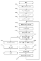
- FIG. It is a flowchart which shows the board
- FIG. It is a figure for demonstrating the method to measure the positional offset amount according to the curvature amount of the two board
- the substrate bonding method is a method of bonding a first substrate and a second substrate, and water or OH is formed on the surface of each bonding surface of the first substrate and the second substrate.
- a step of performing a hydrophilization treatment for adhering a contained substance, and bending the first substrate with respect to an outer peripheral portion of the bonding surface so that a central portion protrudes toward the second substrate In the state of abutting the bonding surface of the second substrate and the bonding surface of the second substrate with each other at the center portion, and in a state where the center portions are butted so as to maintain a constant distance,
- the flatness of the glass stage is about 5 ⁇ m, and by adjusting the parallelism to submicron and controlling the gap, it becomes possible to bring the gap closer to about 10 ⁇ m for the first time up and down without applying pressure. Further, it is preferable to perform bonding in a vacuum because it becomes easy to eliminate voids due to air entrainment even in a gap of 10 ⁇ m.
- the first substrate and the second substrate are arranged with the bonding surfaces facing each other between the hydrophilization treatment step and the bonding step, and the first substrate Between the first substrate and the second substrate so that the amount of positional deviation between the first substrate and the second substrate is small.
- a step of adjusting the relative position is arranged with the bonding surfaces facing each other between the hydrophilization treatment step and the bonding step, and the first substrate Between the first substrate and the second substrate so that the amount of positional deviation between the first substrate and the second substrate is small.
- the above bonding method further includes a step of measuring a positional shift amount between the first substrate and the second substrate during or after the bonding step.
- the outer peripheral portion of the first substrate and the second substrate are in contact with each other so that the central portions keep a constant distance. And the step of returning the deflection of the central portion of the first substrate, and the first substrate and the second substrate so that the positional deviation amount is small. Adjusting the relative position of the substrate and the second substrate, and the first substrate is centered with respect to the outer peripheral portion of the bonding surface until the amount of displacement is within an allowable error range. The process from the step of bending so that the portion protrudes toward the second substrate side to the step of adjusting the relative position between the first substrate and the second substrate is repeated.
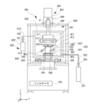
- FIG. 1 is a front view showing a schematic structure inside a substrate bonding apparatus 100 according to an embodiment of the present invention.
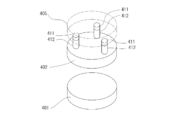
- FIG. 2 is a schematic perspective view showing the vicinity of the stage and the head.
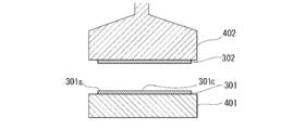
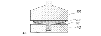
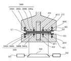
- FIG. 3 is a front sectional view showing the configuration of the stage holding the substrate.
- FIG. 7 is a front sectional view showing another example of the protruding mechanism. In the following description, directions and the like are shown using an XYZ orthogonal coordinate system for convenience.
- the substrate bonding apparatus 100 includes a chamber 200, a substrate (second substrate) 301 that is an object to be bonded, and a substrate support unit 400 that supports the substrate (first substrate) 302 so as to face each other. , A position measuring means (positioning unit) 500 for measuring the relative positional relationship between the substrates 301 and 302, and a hydrophilic treatment means 600 for performing a surface activation process on the surfaces of the substrates 301 and 302 that are supported to face each other. And a controller (control unit) 700 that controls the operation of each unit of the substrate bonding apparatus 100.
- Examples of the substrates 301 and 302 include a glass substrate, an oxide substrate (for example, a silicon oxide (SiO 2 ) substrate, an alumina substrate (Al 2 O 3 )), a nitride substrate (for example, silicon nitride (SiN), and aluminum nitride. (AlN)).
- an oxide substrate for example, a silicon oxide (SiO 2 ) substrate, an alumina substrate (Al 2 O 3 )
- a nitride substrate for example, silicon nitride (SiN), and aluminum nitride. (AlN)
- the chamber 200 has a hollow box shape, and stages 401 and 402 of a substrate support means 400 described later are provided therein.
- the chamber 200 includes a vacuum pump 201 as a evacuation unit for evacuating the inside.
- the vacuum pump 201 is connected to the chamber 200 via the exhaust pipe 202.
- the exhaust pipe 202 is provided with an exhaust valve 203 that opens and closes the exhaust pipe 202.
- the exhaust pipe 202 is opened and the vacuum pump 201 is operated to discharge the gas in the chamber 200 to the outside through the exhaust pipe 202.
- the inside of the chamber 200 is depressurized and evacuated, and the atmosphere in the chamber 200 is brought into a vacuum or low pressure state.
- the exhaust valve 203 can adjust the exhaust flow rate in the exhaust pipe 202 by changing the opening / closing amount thereof, and can adjust the target vacuum degree in the chamber 200.
- ⁇ Distance measuring means for measuring the distance between the stage (second substrate holding unit) 401 holding the substrates 301 and 302 and the stage (first substrate holding unit) 402 before the step of bending the central portion of the substrate 301 or 302. (Not shown).
- the distance measuring means is preferably a device that can measure the distance between stages without contacting the stage, such as a laser distance meter.
- ⁇ Wafer thickness measuring means> Prior to the step of bending the central portion of the substrate 301 or 302, a wafer thickness measuring means (not shown) for measuring the thickness of each of the substrates 301 and 302 is provided.
- the wafer thickness measuring means is preferably capable of measuring the thickness of the substrate without contacting the substrate, such as a laser displacement meter.
- the wafer thickness is measured at three locations with a laser from above and below at the aligner position.
- the required thickness may be calculated by measuring the circumference or the entire surface.
- the distance between the substrates 301 and 302 can be calculated from the measurement results of the distance measuring means and the wafer thickness measuring means.
- the distance between the substrates 301 and 302 is the distance between the bonding surfaces of the substrates 301 and 302, and the stage (second substrate holding unit) 401 and the stage (first substrate holding) measured by the measurement means described above. Part) 402, and can be calculated as a distance obtained by subtracting the thickness of each of the substrates 301 and 302 measured by the wafer thickness measuring means.
- the substrate support means 400 includes a stage (second substrate holding unit) 401, a stage (first substrate holding unit) 402 for supporting the substrates 301 and 302, stage driving mechanisms 403 and 404 for moving the respective stages, and a substrate.
- Substrate heating means 420 for heating.
- Stages 401 and 402 are provided to face each other in the vertical direction (Z direction).
- the upper surface of the lower stage 401 is a support surface of the substrate 301.
- the lower surface of the upper stage 402 is a support surface of the substrate 302.
- the support surfaces of these stages 401 and 402 are arranged in parallel to each other.
- the stages 401 and 402 may have a holding mechanism such as a mechanical chuck, an electrostatic chuck, or a vacuum chuck on each support surface.
- This holding mechanism can switch between a fixed state of the substrates 301 and 302 to the support surface and an open state from the fixed state of the substrates 301 and 302 to the support surface.
- the lower stage 401 includes a stage drive mechanism 403.
- the stage drive mechanism 403 moves the lower stage 401 in the XY ⁇ direction within a horizontal plane orthogonal to the vertical direction (Z direction) in which the stage 401 and the stage 402 face each other.
- the upper stage 402 includes a Z-direction lifting drive mechanism 406 and a Z-axis rotation drive mechanism 407 as the stage drive mechanism 404.
- the stage drive mechanism 404 can further include an XY direction drive mechanism 405.
- the Z-direction lifting / lowering drive mechanism 406 moves the stage 402 in the Z direction, thereby moving the stages 401 and 402 closer to or away from each other along the Z direction. Further, the Z-direction lifting drive mechanism 406 brings the stages 401 and 402 close to each other to bring the bonded surfaces of the held substrates 301 and 302 into contact with each other, and further pressurizes the substrates 301 and 302 that are in contact with each other. be able to.
- the Z direction elevating drive mechanism 406 is provided with a pressure sensor 408 for measuring a force related to the Z axis.
- the pressure sensor 408 detects the pressure acting on the bonding surfaces of the substrates 301 and 302 that are pressed against each other by the Z-direction lift drive mechanism 406.
- a load cell can be used as the pressure sensor 408.
- the XY direction drive mechanism 405 can slide the stage 402 in the XY direction orthogonal to the Z direction where the stage 401 and the stage 402 face each other.
- a plurality of, for example, three projecting mechanisms 412 are provided in the vicinity of the outer periphery of the stage 402 at intervals in the circumferential direction. It has been.
- the protruding mechanisms 412 are independently extended and contracted in the Z direction. By these protrusion mechanisms 412, the distribution of force or pressure acting on the bonding surfaces of the substrates 301 and 302 is finely or accurately adjusted.
- a stage pressure sensor 411 is provided between each protrusion mechanism 412 and the XY direction drive mechanism 405.
- the operation of the protruding mechanism 412 is controlled by a control unit (not shown) according to the distribution of force or pressure acting on the bonding surfaces of the substrates 301 and 302 measured by the plurality of stage pressure sensors 411.
- the stage pressure sensor 411 and the protrusion mechanism 412 further finely adjust the distribution of pressure acting on the substrates 301 and 302 that are pressed against each other by the Z-direction lift drive mechanism 406, and extend over the joint surface. It can be a uniform or predetermined distribution.
- the operation of the Z-direction lifting drive mechanism 406 may be stopped based on the pressure generated on the bonding surface of the substrate 301 and the bonding surface of the substrate 302.
- the pressure generated on the bonding surface of the substrate 301 and the bonding surface of the substrate 302 exceeds a certain value, for example, when the direction in which the substrate is pressed against the counterpart substrate is positive, the pressure generated on the bonding surface of the substrate is When the value is greatly negative, it is considered that a force is working to reduce the distance between the substrates.
- the substrates may be deformed by a force generated in the X or Y direction. When such deformation occurs, positional displacement between the bonded substrates occurs.
- the Z-direction lifting drive mechanism 406 By maintaining the pressure generated on the bonding surface of the substrate 301 and the bonding surface of the substrate 302 at a constant force and stopping the operation of the Z-direction lifting drive mechanism 406 when this pressure exceeds a certain value, time passes. Then, the force to reduce the distance between the substrates is alleviated and returns to a certain value or less. When the pressure generated on the bonding surface of the substrates returns to a certain value or less, the Z-direction lift drive mechanism 406 can be re-driven again.
- the bonding surface of the substrate when the direction in which the substrate is pressed against the counterpart substrate is positive, the bonding surface of the substrate is maintained so that the pressure generated on the bonding surface of the substrate does not become a negative value. It is more preferable to maintain the pressure generated in As an example, when the lower limit value of the pressure generated on the bonding surface of the substrate is set to ⁇ 100 N, the operation speed is controlled or the operation is temporarily stopped when the detected pressure becomes ⁇ 150 N or less. . This can be applied both when the distance between the substrates is reduced and when the distance is removed.
- the pressure generated on the bonding surface of the substrates can be detected by a plurality of stage pressure sensors 411. Thereby, even if the substrate 301 or 302 has thickness variation or distortion, deformation due to pressure generated between the substrates can be suppressed.
- the pressure generated on the bonding surface of the substrate is maintained so as not to exceed a certain value. You may do it.
- the Z axis rotation drive mechanism 407 can rotate the stage 402 around the Z axis.
- the rotational drive mechanism 407 can control the rotational position ⁇ around the Z axis with respect to the stage 401 with respect to the stage 401, thereby controlling the relative positions of both substrates 301 and 302 in the rotational direction.
- control unit evacuates the atmosphere around the first substrate and the second substrate in the chamber so that the air can be bonded without voids. It becomes possible.
- the microelectrode portion made of Cu is subjected to CMP polishing in a dented state, and the insulating layer is first bonded at a low temperature of about 150 ° C. Then, there is a method in which the Cu electrodes are expanded by heating to about 350 ° C. to fill the gaps and diffusely bond Cu to each other.
- the gap between the Cu electrodes is filled with the atmosphere, and the surface of the Cu electrode is oxidized in the heating and expansion process, which is not preferable for joining.
- the air in the gap remains void as it has nowhere to go.
- SiO 2 which is a constituent material of the substrate, when a Cu electrode is included in the bonding surface, it is more preferable to apply heat and pressure in the bonding step.
- the gap is vacuumed by bonding in vacuum, so that oxidation can be suppressed and generation of voids can also be suppressed.
- the timing of evacuation it is possible to correct misalignment because there are many water molecules in the contact part by securing the atmospheric environment in the state where the center part is in contact, but it is a short time within a few minutes.
- the degree of vacuum is about several hundred Pa, it is possible to leave water molecules at the interface to some extent even if vacuuming is performed from the beginning.
- the entire surface can be secured in a vacuum atmosphere while interposing water molecules. If position correction after contact is not required, a vacuum may be drawn from the beginning.
- the alignment process between the first substrate and the second substrate may be performed before releasing the bent substrate or after evacuation.
- the time required for alignment is several seconds to several tens of seconds, and does not affect the bonding of the substrates.
- a stage 402 (or stage 401) not holding a substrate while holding only one of the substrates 301 (or substrate 302) before the step of bending the central portion of the substrate.
- a distance measuring means (not shown) for measuring the distance between the substrate and the held substrate.
- the distance measuring means is preferably a laser distance meter provided in the stage 402 (or stage 401), for example, and can measure the distance from the opposing stage or the upper surface of the substrate to the stage without contacting the opposing stage or substrate. .
- the distance between the substrates 301 and 302 can be calculated from the measurement results of the distance measuring means and the wafer thickness measuring means. For example, it is possible to obtain the inter-stage distance from the difference between the reflected light on the upper surface of the lower glass stage and the reflected light on the lower surface of the upper glass stage by introducing laser light from the upper part of the head side upper glass stage. When the wafer is on the lower stage, the distance between the lower surface of the upper glass stage and the upper surface of the lower wafer can be obtained.
- distance measuring means (not shown) is provided for measuring the distance between the bonding surfaces of the substrate 301 and the substrate 302 in a state where the substrate 301 and the substrate 302 are held on the stages 401 and 402. Also good. Specifically, a mode in which a distance measuring unit capable of measuring the distance between the bonding surfaces of the substrate 301 and the substrate 302 is inserted between the substrates to measure the distance between the substrates can be mentioned.
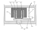
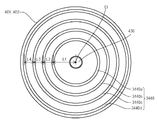
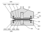
- a protruding mechanism 430 that can be projected and retracted toward the lower stage 401 side is built in the central portion of the support surface that supports the substrate 302.
- the protruding mechanism 430 can employ a cylinder structure or an electromagnetic mechanism. It is preferable that the protrusion mechanism 430 has at least a force that bends the substrate 302 and has a function of moving in a direction opposite to the protruding direction when receiving a force in a direction opposite to the protruding direction for a certain amount.
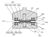
- the protruding mechanism 430 includes a pressing member 434 that presses the substrate 302, a voice coil motor 433, and a displacement sensor 435.
- the voice coil motor 433 includes a bottomed cylindrical coil bobbin 4331, a coil 4332 wound around the coil bobbin 4331, a magnet 4333 disposed to face the coil 4332, and a bottomed cylindrical part covering the outside of the coil 4332.
- a yoke 4334 configured from a bottom portion of the bottomed cylindrical portion and a protruding portion fitted inside the coil 4332.
- the pressing member 434 is fixed to the bottom of the coil bobbin 4331 of the voice coil motor 433.
- a yoke 4334 of the voice coil motor 433 is fixed to the stage main body 4021.
- the voice coil motor 433 when a current flows through the coil 4332, the coil bobbin 4331 moves along the cylinder axis direction.
- the pressing member 434 fixed to the coil bobbin 4331 moves in a direction protruding from the stage 402 or a direction immersing in the stage 402. Then, by controlling the magnitude of the current flowing through the coil 4332, the pressure applied to the substrate 302 by the pressing member 434 fixed to the coil bobbin 4331 can be controlled.
- the pressing member 434 includes a protruding portion 4341 that protrudes from the stage main body 4021 to the outside, and a flat base portion 4342 that is formed integrally with the protruding portion 4341.
- the displacement sensor 435 is comprised, for example from an eddy current type displacement sensor, and measures the distance LH between the detection part 435a and the base part 4342 of the press member 434.
- FIG. The substrate bonding apparatus 100 can execute position control of the pressing member 434 fixed to the coil bobbin 4331 based on the distance LH measured by the displacement sensor 435.
- the protruding mechanism 430 uses the voice coil motor 433, pressure control when the pressing member 434 presses the substrate 302 and position control of the pressing member 434 are possible.
- the substrate bonding apparatus 100 when the substrate bonding apparatus 100 performs pressure control while pressing the substrate 302 with the pressing member 434, if the position of the pressing member 434 is out of a preset range, the substrate bonding apparatus 100 controls the pressing member 434. By switching to position control, the pressing member 434 can be returned to a preset range. As described above, the substrate bonding apparatus 100 can combine pressure control and position control of the pressing member 434.
- a protrusion mechanism it may have a cylinder structure, for example, and can change a pressurizing force by changing the air pressure supplied in a cylinder.
- a protrusion mechanism it is an electromagnetic coil type
- the projecting mechanism is pushed down by bringing the substrates closer to each other by the vertical movement axis between the substrates, for example, the Z axis in this embodiment, to bring the distance between each substrate of the head or stage from the bent state.
- the contact area can be increased from the center to the outer periphery, following the other flat substrate.
- the speed of wetting and spreading can be controlled by numerically controlling the distance between the substrates.
- the wetting speed is different, and the conventional method of inserting the claw between the wafers and pulling it out and dropping it naturally causes voids, so speed control is an effective method.
- the distance from the bottom surface of each substrate to the center portion can be expanded and contracted according to the Z-axis movement of the head.
- the contact area can be increased to the outer peripheral portion by moving the outer peripheral portion closer while maintaining the same upper and lower sides.
- the alignment mark position of the substrate on one side is also shifted inward, resulting in poor alignment accuracy and distortion during joining.
- the alignment mark position can be brought to the same position, and bonding can be performed without causing distortion at the time of joining, which is an effective method compared to a conventional one-side protruding mechanism.
- the amount of protrusion that required 20 ⁇ m on one side can be accommodated at 10 ⁇ m on both sides, resulting in less distortion.
- this method is particularly effective in the field of simultaneously bonding a microelectrode called a hybrid bonding that requires submicron accuracy and a peripheral insulating layer, for example, a CMOS image sensor, a memory, an arithmetic element, and a MEMS.
- both end marks of the substrate are read with an image processing device, and the amount of displacement is corrected and then moved for correction. If water molecules exist at the interface between the two substrates and the applied pressure is small, although the correction movement can be performed in the contact state, when the contact area is large, the protrusion mechanism may be pulled back once to provide a correction movement with a gap between both substrates. Further, it is possible to provide a gap by moving the Z-axis without changing the protruding mechanism. Moreover, a clearance gap can also be provided using both.
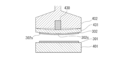
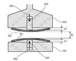
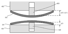
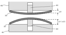
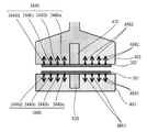
- FIG. 5 is a front sectional view showing a state in which the substrate 302 is bent by the protruding mechanism 430 provided in the stage 402.
- the protrusion mechanism 430 when the protrusion mechanism 430 is protruded from the stage 402, the outer peripheral portion 302s of the substrate 302 receives a downward force due to its own weight so that the central portion 302c of the substrate 302 protrudes upward.
- “protruding mechanism 430 protrudes from stage 402” means that the pressing member 434 of the protruding mechanism 430 protrudes from the stage 402 in detail.
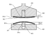
- the pressing by the protruding mechanism 430 is released, or when the substrate 302 is abutted against the opposing substrate 301 and receives a force exceeding a certain level, the substrate 302 is restored to the original flat plate shape.
- the top portion 430a that contacts the substrate of the protruding mechanism 430 may have a curved shape as shown in FIG. Thereby, a board
- the bonding of the central portion 301 c of the substrate 301 is performed separately from the method for defining the bonding position as described above. It is preferable to reduce the distance between the outer peripheral portion 301 s of the substrate 301 and the outer peripheral portion 302 s of the substrate 302 by the protruding distance of the surface with respect to the bonding surface of the outer peripheral portion 301 s of the substrate 301.
- the distance between the outer peripheral portion 301 s of the substrate 301 and the outer peripheral portion 302 s of the substrate 302 is reduced by a distance equivalent to the protruding distance of the protruding mechanism 430.
- the bonding position can be determined from the pushing amount of the protruding mechanism 430 measured by the above-described displacement sensor 435.
- the detection value of the displacement sensor 435 at the abutting position is stored, and the protrusion amount can be calculated from the difference from the detection value of the displacement sensor 435 when protruding.
- the vertical protrusion amount may be added.
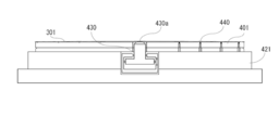
- the stages 401 and 402 may have a holding mechanism 440 such as a mechanical chuck, an electrostatic chuck, or a vacuum chuck on each support surface.
- This holding mechanism can switch between a fixed state of the substrates 301 and 302 to the support surface and an open state from the fixed state of the substrates 301 and 302 to the support surface.
- the holding mechanism may be divided into a plurality of regions on the surfaces of the stages 401 and 402 as shown in FIG.
- two holding mechanisms an outer holding mechanism 440a and an inner holding mechanism 440b
- the outer holding mechanism 440a and the inner holding mechanism 440b can be controlled independently, and the inner holding mechanism 440b is opened while the outer holding mechanism 440a holds the outer peripheral portion of the substrate, and the Z-axis is formed in the central portion of the substrate. It is possible to avoid receiving force in the direction.
- holding mechanisms 440 When a plurality of holding mechanisms 440 are provided, for example, holding mechanisms having different principles and functions, such as an electrostatic chuck and a vacuum chuck, may be used in combination.
- electrostatic chuck electrodes and vacuum chuck suction grooves may be provided alternately in the radial direction of the stage.
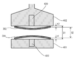
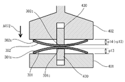
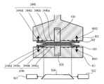
- a mechanism similar to the protruding mechanism 430 may be provided on the lower stage 401 side. As shown in FIG. 7, by adopting a configuration in which the substrates 301 and 302 are bent by both the stages 401 and 402, the amount of bending of the substrate is reduced, and the substrate can be aligned with less error.
- the lower substrate 301 When the lower substrate 301 is bent, it is preferable to hold only the outer peripheral portion 301 s of the substrate 301. In this case, it is preferable that only the outer peripheral portion 301s of the substrate 301 is held by the outer holding mechanism 440a because the substrate bends to a desired shape even if the force of pressing the substrate by the protruding mechanism 430 is weak.
- the suction groove provided on the stage may be separated by the location of the substrate.
- the suction groove for holding the peripheral portion of the substrate and the suction groove for holding the central portion of the substrate may be separated and each may operate separately. Thereby, only the outer peripheral part of a board
- the central part is first vacuum-adsorbed, and when it bends, it breaks down to the atmospheric pressure.
- the substrate can be easily peeled off by releasing pressurized air for a few seconds.
- the substrate is difficult to peel off at the mirror surface, it is possible to make it easy to peel off while maintaining the height accuracy by intentionally roughening the holding portion contact surface.
- the bonded substrate assembly may have variations in warpage and thickness.
- the entire surface of the lower stage 401 is again vacuum-sucked to reduce warpage and thickness variations in the substrate assembly. be able to.
- the holding mechanism 440 when the holding mechanism 440 is of the electrostatic chuck type, the holding mechanism is divided into a plurality of regions on the surfaces of the stages 401 and 402 as shown in an example in FIG. May be.
- two different patterns that can be individually controlled are provided, that is, the outer holding mechanism 440a and the inner holding mechanism 440b.
- the outer holding mechanism 440a and the inner holding mechanism 440b can be controlled independently, and the inner holding mechanism 440b is opened while the outer holding mechanism 440a holds the outer peripheral portion of the substrate, and the Z-axis is formed in the central portion of the substrate. It is possible to avoid receiving force in the direction.
- the vacuum suction groove in the central portion is used together to break the vacuum to atmospheric pressure.
- the substrate can be easily peeled off by releasing pressurized air for a few seconds.
- the holding mechanism may be divided into three, and one or more grooves may be inserted between the central portion and the outer peripheral portion to provide an air release layer.
- both the leaks are absorbed by the air release layer between the central part and the central part even when the central part releases pressurized air while maintaining the vacuum at the outer peripheral part. Even if the holding is peeled off or air is released, it is possible to prevent the central portion from being bent due to being sucked by the outer peripheral portion, which is effective.
- the adsorbing part and the atmosphere releasing part are not limited to the grooves, and may be configured to support a plurality of points in the plane.
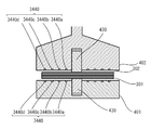
- a support plate that supports the substrate 302 may be provided with a pressing plate 431 having a thin plate shape and flexibility.
- the pressing plate 431 may have a holding mechanism (not shown) such as a vacuum suction method, a mechanical chuck, or an electrostatic chuck on a support surface that supports the substrate 302.
- the pressing plate 431 is elastically deformed, and the center portion 431c is bent so as to protrude downward.
- the pressing plate 431 is bent so as to protrude downward, whereby the central portion 302c of the substrate 302 on which the outer peripheral portion 302s is held by the holding mechanism (not shown) is directed toward the lower stage 401. Pressed. Then, the substrate 302 is elastically deformed along the pressing plate 431, and is bent so that the central portion 302c is convex downward with respect to the outer peripheral portion 302s.
- the entire substrate 302 is pressed and bent, so that the substrate 302 can be prevented from being distorted.
- the pressing by the protruding mechanism 430 is released, the substrate 302 is restored to the original flat shape.
- the substrate heating means 420 includes heaters 421 and 422 built in stages 401 and 402.
- the heaters 421 and 422 are configured to generate Joule heat with, for example, an electric heater.
- the heaters 421 and 422 conduct heat through the stages 401 and 402 to heat the substrates 301 and 302 supported by the stages 401 and 402.
- Stages 401 and 402 and heaters 421 and 422 may be formed of separate members.
- the stages 401 and 402 including the holding mechanism 440 may be overlapped with the heaters 421 and 422 including the heater wiring. An example is shown in FIG.
- It can also be joined as it is by heating with a heater of a joining device, but it can also be joined by taking it out in a bonded state and annealing it at 150 ° C. for several hours in a batch furnace or hot plate in a free state without pressure. .
- the position measuring unit 500 measures the relative positional relationship between the substrates 301 and 302.
- the position measuring means 500 includes a window 503 formed in the chamber 200, a light source (not shown), a plurality of cameras 501 and 502, and mirrors 504 and 505.
- Light emitted from a light source (not shown) passes through mirrors 504 and 505 and a window 503 and strikes portions (not shown) provided with marks on the substrates 301 and 302.
- the cameras 501 and 502 capture an image of reflected light from a portion (not shown) provided with marks on the substrates 301 and 302 through a window 503 and mirrors 504 and 505.
- the cameras 501 and 502 each have a coaxial illumination system.
- the light source may be provided on the upper side of the stage 401 or may be provided so as to emit light from the cameras 501 and 502 side so as to travel along the optical axis.
- a wavelength region for example, the substrate can be made of silicon that passes through portions where the marks are provided on the substrates 301 and 302 and portions where the light should pass such as both stages. If it is, infrared light) is used.
- infrared transmission recognition is performed with the bonding surface of the substrate 301 and the bonding surface of the substrate 302 maintained at a distance that maintains the non-bonded state between the entire surfaces. It can be carried out.
- the relative positions of the substrates arranged opposite to each other may be measured by the cameras provided on the stages 401 and 402 side.
- the substrate bonding apparatus 100 can measure and align the relative positions of the substrates 301 and 302 using the position measuring means 500, the driving mechanisms 403 to 407, and the controller 700 connected thereto.
- the locations where light for measurement passes are defined on the substrates 301 and 302, and a mark is attached here to reflect, block or refract part of the passing light.
- the alignment mark appears dark in the captured bright field image.
- the reflected light from the alignment mark is received, the mark appears bright in a dark image.
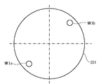
- a plurality of alignment marks are provided on the substrate, for example, at two opposite corners of the substrate. Thereby, the absolute position of the substrate 301 or 302 can be specified from the positions of the plurality of alignment marks.
- corresponding alignment marks are attached to corresponding portions of the substrates 301 and 302, for example, positions overlapping in the Z direction during bonding. Both alignment marks on the substrates 301 and 302 are observed within the same field of view, and the relative displacement amounts in the X and Y directions are measured. By measuring the relative displacement amounts in the X direction and the Y direction at a plurality of locations, the relative displacements ( ⁇ X, ⁇ Y, ⁇ ) of the substrates 301 and 302 in the X direction, Y direction, and ⁇ direction are calculated. Can do.
- the measurement operation of the positional deviation amount in the position measuring means 500 can be executed when the substrates 301 and 302 are in a non-contact state or a contact state.
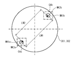
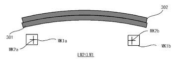
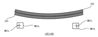
- the substrate 301 is provided with two alignment marks (first alignment marks) MK1a and MK1b for alignment. Further, as shown in FIG. 11, the substrate 302 is also provided with two alignment marks (second alignment marks) MK2a and MK2b for alignment. Images obtained by photographing the alignment marks MK1a, MK1b, MK2a, and MK2b relating to both the substrates 301 and 302 are as shown in FIG. 12, for example.
- the position measuring means 500 uses both images (image data) GA relating to transmitted light and reflected light of illumination light emitted from the respective coaxial illumination systems of the cameras 501 and 502 in a state where both the substrates 301 and 302 face each other.
- the positions of the substrates 301 and 302 can also be recognized.
- the positional deviation measurement for the alignment operation (fine alignment operation) of both the substrates 301 and 302 is performed by the cameras 501 and 502 with two sets of alignment marks (MK1a and MK2a) attached to both the substrates 301 and 302. ) And (MK1b, MK2b) are simultaneously recognized.
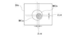
- the position measuring means 500 acquires an image GAa including alignment marks MK1a and MK2a and an image GAb including alignment marks MK1b and MK2b as shown in FIG. 12, and attaches them to both substrates 301 and 302 based on the images GAa and GAb.
- the position of each set of marks (MK1a, MK2a), (MK1b, MK2b) is recognized.
- the controller 700 Based on the relative positions of the recognized marks (MK1a, MK2a) and (MK1b, MK2b), the controller 700 detects the amount of misalignment between the marks (MK1a, MK2a) and (MK1b, MK2b) as shown in FIG. ⁇ xa, ⁇ ya) can be obtained.
- FIG. 12 shows a state in which each set of marks (MK1a, MK2a), (MK1b, MK2b) is in a desired position with their centers overlapping each other
- FIG. 13 shows a set of marks (MK1a, MK2a). ) Shows a state of being deviated from the desired position.
- each image GAa, GAb (image GAa is shown in FIG. 13) is positioned for each set of marks based on the geometric relationship of the marks on the substrates 301, 302. Deviation amounts ( ⁇ xa, ⁇ ya) and ( ⁇ xb, ⁇ yb) are obtained.
- the controller 700 detects X from the desired positions of the substrates 301 and 302 based on the positional deviation amounts ( ⁇ xa, ⁇ ya) and ( ⁇ xb, ⁇ yb) of the two sets of marks (MK1a, MK2a) and (MK1b, MK2b).
- a relative deviation amount ⁇ D (specifically, ⁇ x, ⁇ y, ⁇ ) in the direction, the Y direction, and the ⁇ direction is calculated.
- the relative deviation amount ⁇ D corresponds to the correction movement amount by the subsequent correction movement.
- the controller 700 finally adjusts the substrates 301 and 302 by a correction amount ⁇ D ( ⁇ x, ⁇ y, ⁇ ) corresponding to the relative deviation amount ⁇ D ( ⁇ x, ⁇ y, ⁇ ) between the substrates 301 and 302.
- the path of the correction movement that moves is calculated.
- the controller 700 instructs the drive mechanisms 403 to 407 of the stages 401 and 402 to move both the substrates 301 and 302 according to the calculated correction path.
- the correction movement is performed so that the relative deviation amount ⁇ D is zero or reduced.
- stage driving is performed so that the stage 402 that supports the substrate 302 finally moves by a correction amount ( ⁇ D) with respect to the stage 401 that supports the substrate 301.
- the mechanisms 403 and 404 are controlled.
- the stage driving mechanisms 403 and 404 drive the two translational directions (X direction and Y direction) and the rotational direction ( ⁇ direction) and the stage 402 in accordance with an instruction from the controller 700.
- the relative displacement is made, and the positional deviation amount ⁇ D is corrected.
- the correction movement is considered to be performed in a state where the bonding surfaces of the substrates are separated from each other and in a state where they are in contact with each other. Each correction movement will be described below.
- the positional deviation amount ⁇ D (specifically, ⁇ x, ⁇ y, ⁇ ) in the plane (horizontal plane) perpendicular to the vertical direction (Z direction) is measured, and an alignment operation (correction is performed for the positional deviation amount ⁇ D). Fine alignment operation) is executed.
- the present invention is not limited to this.
- the images GAa and GAb may be sequentially captured and acquired by moving one camera in the X direction and / or the Y direction.
- each set of marks was imaged simultaneously on the same optical axis, the present invention is not limited to this.
- two sets (a total of four) cameras arranged for the respective substrate positions may be used. If the positional relationship of the optical axes of the cameras is known, each of the corresponding marks (MK1a, MK2a) is imaged by each camera and then combined to obtain a substantially joined position in the translation direction. It can be moved and positioned.
- the substrate bonding apparatus 100 includes hydrophilic treatment means 600.
- the hydrophilic treatment means 600 of the substrate bonding apparatus 100 shown in FIG. 1 includes an activation processing unit 610 that activates the bonding surfaces of the substrates 301 and 302, and a hydrophilic treatment that hydrophilizes the activated bonding surfaces of the substrates 301 and 302. And a processing unit 620.
- the activation processing unit 610 removes the surface layer by causing a phenomenon (sputtering phenomenon) in which particles having a predetermined kinetic energy collide with each other in a vacuum to physically blow off the material forming the bonding surface. be able to.
- a phenomenon sputtering phenomenon
- the surface activation treatment not only the surface layer is removed to expose the nascent surface of the substance to be bonded, but also the crystal structure near the exposed nascent surface is collided with particles having a predetermined kinetic energy. It is thought that there is also an effect of disturbing and amorphizing.
- the amorphized new surface has a higher surface area at the atomic level and a higher surface energy, it is considered that the number of hydroxyl groups (OH groups) per unit surface area to be bonded in the subsequent hydrophilization treatment is increased.
- OH groups hydroxyl groups
- the hydrophilization treatment following the surface activation treatment according to the bonding method of the invention is fundamentally different from the conventional hydrophilization treatment in this respect.
- atoms in the vicinity of the nascent new surface that are disordered due to the crystal structure are easily diffused with relatively low thermal energy during the heat treatment during the main bonding, realizing a main bonding process at a relatively low temperature. I think it can be done.
- a rare gas or an inert gas such as neon (Ne), argon (Ar), krypton (Kr), or xenon (Xe) can be used. Since these rare gases have a relatively large mass, it is considered that a sputtering phenomenon can be efficiently generated and the crystal structure of the nascent surface can be disturbed.
- oxygen ions As the particles used for the surface activation treatment, oxygen ions, atoms, molecules, and the like may be employed. By performing the surface activation treatment using oxygen ions or the like, it is possible to cover the nascent surface with an oxide thin film after removing the surface layer.
- the oxide thin film on the nascent surface is believed to enhance the efficiency of hydroxyl (OH) group bonding or water attachment in subsequent hydrophilization treatments.
- OH hydroxyl
- the oxide thin film formed on the nascent surface is relatively easily decomposed during the heat treatment in the main bonding.
- the kinetic energy of the particles colliding with the surface-activated joint surface is 1 eV (electron volts) to 2 keV. It is considered that the above kinetic energy efficiently causes a sputtering phenomenon in the surface layer.
- a desired value of kinetic energy can also be set from the above kinetic energy range according to the thickness of the surface layer to be removed, the properties such as the material, the material of the new surface, and the like.
- a predetermined kinetic energy can be given to the particles that collide with the surface-activated joint surface by accelerating the particles toward the joint surface.
- a predetermined kinetic energy can be given to the particles using a plasma generator.
- a plasma generator By applying an alternating voltage to the bonding surface of the substrate, a plasma containing particles is generated around the bonding surface, and the cations of the ionized particles in the plasma are accelerated toward the bonding surface by the voltage.
- given kinetic energy is given. Since the plasma can be generated in an atmosphere with a low degree of vacuum of about several pascals (Pa), the vacuum system can be simplified and the steps such as evacuation can be shortened.
- the particle beam source operates in a relatively high vacuum, such as 1 ⁇ 10 ⁇ 2 Pa (pascal) or 1 ⁇ 10 ⁇ 5 Pa or less, so unnecessary oxidation or renewal of the regenerated surface after the surface activation treatment is performed. Impurities can be prevented from adhering to the surface. Furthermore, since the particle beam source can apply a relatively high acceleration voltage, high kinetic energy can be imparted to the particles. Therefore, it is considered that the removal of the surface layer and the amorphization of the new surface can be performed efficiently.
- the plasma generator operates at 100 W and generates plasma of nitrogen (N 2 ), oxygen (O 2 ), and argon (Ar) as a hydrophilic treatment, and this plasma is applied to the bonding surface for about 30 seconds. If used to irradiate, treatment for hydrophilization can be performed.
- the plasma generator may be installed separately from the bonding apparatus so as to connect in the vacuum or handle the atmosphere once.
- Neutral atoms or ions can also be used for the particles used for surface activation.
- a predetermined kinetic energy can be given to the particles using a particle beam source such as a neutral atom beam source or an ion beam source (ion gun) disposed at a position separated from the bonding surface.
- the particles to which a predetermined kinetic energy is applied are emitted from the particle beam source toward the bonding surface of the substrate.
- nitrogen (N 2 ), oxygen (O 2 ), argon (Ar), or the like may be used as a reaction gas.
- a fast atom beam source As the neutral atom beam source, a fast atom beam source (FAB, Fast Atom Beam) can be used.
- FABs Fast atom beam sources
- FABs typically generate a plasma of gas, apply an electric field to the plasma, extract the cations of particles ionized from the plasma, and pass them through an electron cloud. It has the composition which becomes.
- the power supplied to the fast atom beam source (FAB) may be set to 1.5 kV (kilovolt), 15 mA (milliampere), or 0.1 W You may set to the value between (watt) and 500W (watt).
- a fast atom beam source FAB
- a fast atom beam source FAB
- 100 W watts
- 200 W watts
- a fast atom beam of argon (Ar) for about 2 minutes the oxide, contaminants, etc. (surface) Layer) can be removed to expose the nascent surface.
- the ion beam source (IG) may be used to operate at 110 V, 3 A, for example, to accelerate argon (Ar) and irradiate the bonding surface for about 600 seconds.
- the particles used for surface activation may be neutral atoms or ions, may be radical species, and may be a particle group in which these are mixed.
- the removal rate of the surface layer can vary. Therefore, it is necessary to adjust the treatment time required for the surface activation treatment. For example, the presence of oxygen and carbon contained in the surface layer is confirmed using surface analysis methods such as Auger Electron Spectroscopy (AES, Auger Electron Spectroscopy) and X-ray Photoelectron Spectroscopy (XPS, X-ray Photo Electron Spectroscopy). You may employ
- Auger Electron Spectroscopy Auger Electron Spectroscopy
- XPS X-ray Photoelectron Spectroscopy
- the irradiation time of the particles may be set longer than the time necessary for removing the surface layer and exposing the new surface.
- the lengthening time may be set to 10 to 15 minutes, or 5% or more of the time required for removing the surface layer and exposing the new surface.
- the time for making the bonding surface amorphous in the surface activation treatment may be appropriately set according to the type and nature of the material forming the bonding surface and the irradiation conditions of particles having a predetermined kinetic energy.
- the kinetic energy of the irradiated particles is set to be 10% or more higher than the kinetic energy necessary for removing the surface layer and exposing the new surface. Good.
- the kinetic energy of the particles for making the bonding surface amorphous in the surface activation treatment may be appropriately set depending on the type and property of the material forming the bonding surface and the irradiation conditions of the particles.
- the “amorphized surface” or “surface with disordered crystal structure” specifically includes an amorphous layer whose presence has been confirmed by measurement using a surface analysis technique or a layer with a disordered crystal structure, This is a conceptual term that expresses the state of the crystal surface assumed when the particle irradiation time is set to be relatively long or the particle kinetic energy is set to be relatively high. It includes a surface in which the presence of an amorphous layer or a surface having a disordered crystal structure is not confirmed by the measurement used. Also, “amorphize” or “disturb the crystal structure” conceptually represents the operation for forming the amorphized surface or the surface in which the crystal structure is disturbed.
- the Si particle beam can be emitted simultaneously with the Ar particle beam by interposing a material containing Si in the casing.
- the interface is doped with Si, an interface with more active Si is formed, and more OH groups are formed when the hydrophilic treatment is performed, thereby increasing the strength. This is particularly effective for increasing the bonding strength in a vacuum.
- the bonding strength of the Si wafer with oxide film in vacuum is 1.5 J / m 2 without the Si plate.
- the strength is increased to a bulk breakdown of 2.5 J / m 2 or more.
- the particle beam treatment by FAB or IG may be transported in the atmosphere or connected as a separate device in addition to being arranged in the joining device.
- the hydrophilic treatment unit 620 bonds a hydroxyl group (OH group) to the bonding surface of the substrates 301 and 302 cleaned or activated by the activation processing unit 610.
- the hydrophilic treatment by the hydrophilic treatment unit 620 is performed by supplying water (H 2 O) around the bonding surfaces of the surface activated substrates 301 and 302 in the chamber 200. Therefore, the hydrophilization processing unit 620 includes a water gas generator 621, a valve 622, and a water gas supply pipe 623.
- the supply of water is performed by introducing, for example, gaseous water (H 2 O) into the atmosphere around the surface activated bonding surface.
- Gaseous water is generated by bubbling the argon (Ar) carrier gas through the water gas generator 621 in the form of bubbles.
- Gaseous water is mixed with the carrier gas, controlled to a desired flow rate by the valve 622, and introduced into the chamber 200 through the water gas supply pipe 623.
- the carrier gas at this time is not limited to argon (Ar), and may be nitrogen (N 2 ), helium (He), oxygen (O 2 ), or the like.
- water may be water vapor, or may be introduced into the chamber 200 by spraying liquid water in a mist form.
- radicals, ionized OH groups, or the like may be attached.
- the substrate may be cooled in order to allow water to adhere to the bonding surface of the substrate, and the bonding apparatus of this embodiment may include a cooling device for this purpose. Even when the environmental humidity is about 50%, the humidity of the substrate surface can be raised to about 85 to 100% by cooling the substrate.
- water In the hydrophilization treatment, water, hydroxide, hydroxide ion (OH ⁇ ), hydroxyl radical ( ⁇ OH), or a substance represented by OH is formed on the bonding surface that has been subjected to the surface activation treatment.
- OH-containing substances such as ions and radicals (hereinafter also referred to as “water”) are attached to form a layer terminated with a hydroxyl group (OH group) (M—OH) on the bonding surface. Is done.
- water or OH-containing substance the substance to be attached to the bonding surface subjected to the surface activation treatment
- water etc. these are collectively called “water etc.”, or more simply “water”.
- water H 2 O
- the hydrophilization process can be controlled by controlling the humidity of the atmosphere around the bonding surfaces of the surface-activated substrates 301 and 302.
- the humidity may be calculated as relative humidity, may be calculated as absolute humidity, or other definitions may be employed.
- the introduction of water is preferably controlled so that the relative humidity in the atmosphere around at least one or both of the joint surfaces of both substrates is 10% to 90%.
- the total pressure in the chamber is 9.0 ⁇ 10 4 Pa (Pascal), that is, 0.89 atm (Atom )
- the amount of gaseous water in the chamber is 8.6 g / m 3 (gram / cubic meter) or 18.5 g / m 3 (gram / cubic meter) in absolute volume humidity, 23 ° C. (23 degrees Celsius)
- the relative humidity can be controlled to be 43% or 91%, respectively.
- the atmospheric concentration of oxygen (O 2 ) in the chamber may be 10%.
- air outside the chamber having a predetermined humidity may be introduced.
- air it is preferable that the air passes through a predetermined filter in order to prevent unwanted impurities from adhering to the bonding surface.
- water (H 2 O) molecules or clusters may be accelerated and radiated toward the bonding surface.
- the acceleration of the water (H 2 O) may be used, such as particle beam source used for the surface activation treatment.
- a mixed gas of carrier gas and water (H 2 O) generated by bubbling or the like is introduced into the particle beam source, thereby generating a water particle beam, and on the joint surface to be hydrophilized. It can be irradiated towards.
- the hydrophilization treatment may be performed by converting water molecules into plasma and bringing it into contact with the joint surface in an atmosphere near the joint surface.
- water washing may be performed as a hydrophilic treatment to remove particles (contaminated particles).
- hydrophilic treatment You may perform the same kind or different kind of hydrophilic treatment in multiple times. Also, As part of the hydrophilization treatment, Or after hydrophilization treatment Water molecules may be forced to adhere to the joint surface. This The amount of water molecules on the joint surface can be increased or controlled. Moreover, Thereby, the critical pressure can be adjusted.
- the surface where the surface activation treatment and the hydrophilization treatment have been performed is bonded with water molecules intervening as described above, but hydrogen bonds between OH groups can be achieved by removing water molecules. By attracting each other, a relatively strong temporary joint is formed. Further, since a bonding interface including hydrogen and oxygen is formed, hydrogen and oxygen are released to the outside of the bonding interface by the heat treatment in the main bonding, and a clean bonding interface can be formed.
- the method of applying pressure and the method of heating were shown as the bonding method.
- pressure exceeding the critical pressure for example, by pressurizing at 10 MPa
- water molecules are pushed to join between OH groups. Change.
- heat water molecules are removed from the interface and changed to bonding between OH groups. After that, by continuing the heating, the hydrogen bond is changed to the covalent bond, and a transition is made to a strong main junction state.
- the same temporary bonding state can be maintained by bonding after leaving water in a vacuum for a long time to blow off water molecules.
- Bonding can be performed by applying pressure from a bonding state in which water molecules intervene, or bonding in a vacuum. Thereafter, heating can be used in combination in order to make a transition to strong bonding. It is also possible to make a transition to strong bonding from the beginning by heating.
- heating involves thermal expansion of the substrate, it is effective to heat in a state where the substrate is temporarily bonded by pressurization or bonding in vacuum.
- Oxide may be formed on the joint surface by the hydrophilic treatment.
- a hydroxyl (OH) group directly on the new surface without adhesion of impurities by continuously adhering water, etc.
- water molecules adhere to the hydroxyl (OH) group.
- this oxide is relatively controlled (for example, a thickness of several nm or several atomic layers or less), it does not particularly deteriorate electrical characteristics.
- heat treatment after pasting it can be absorbed in the metal material, or can be eliminated or reduced by escaping from the bonding interface as water. Therefore, in this case, it is considered that there is almost no practical problem in the conductivity through the bonding interface with the substrate.
- a measurement process for measuring the inter-stage distance and the wafer thickness is executed (step S100).
- the measurement process is performed before the process of bending the central portion of the substrate.
- the substrate is held in a state where only one of the substrates 301 (or the substrate 302) is held before the step of bending the central portion of the substrate.
- the distance between the stage 402 (or stage 401) not held and the held substrate may be measured, and the distance between the substrates 301 and 302 may be calculated from the measurement result and the measurement result of the wafer thickness measuring means. .
- the distance between the bonding surfaces of the substrate 301 and the substrate 302 may be measured in a state where the substrate 301 and the substrate 302 are held on the stages 401 and 402.
- a hydrophilic treatment process is executed (step S101).
- the hydrophilic treatment is performed on the surfaces of the bonding surfaces of the substrate 301 and the substrate 302.
- the hydrophilic treatment process first, as shown in FIG. 3, the substrate 301 is held by a holding mechanism (not shown) of the stage 401 of the substrate bonding apparatus 100, and the outer periphery of the substrate 302 is held by the holding mechanism (not shown) of the stage 402. The part 302s is held. In this state, the substrate 301 and the substrate 302 are opposed to each other with their bonding surfaces being separated from each other.
- the chamber 200 is opened to the atmosphere, and the atmosphere is introduced into the atmosphere around the substrates 301 and 302 in the chamber 200.
- the bonding surfaces of the substrates 301 and 302 are activated by any of the activation treatment methods described above.
- plasma-processed argon (Ar) is caused to collide with the bonding surfaces of the substrates 301 and 302 to perform a sputtering process.
- the surface layer of the bonding surfaces of the substrates 301 and 302 is removed, and the nascent surface of the substance to be bonded is exposed, and the crystal structure in the vicinity of the exposed nascent surface is disturbed and becomes amorphous.
- the activated bonding surfaces of the substrates 301 and 302 are hydrophilized by any of the hydrophilic treatment methods described above.
- the water gas generator 621 generates gaseous water, and the generated gaseous water is introduced into the chamber 200 through the water gas supply pipe 623 together with the carrier gas.
- a hydrophilic treatment is performed by attaching an OH-containing substance such as water to the bonding surfaces of the substrates 301 and 302 that have been subjected to the surface activation treatment, the bonding surfaces are terminated with hydroxyl groups (OH groups) (M-OH). ) Is formed.
- step S100 interstage distance and wafer thickness measurement step
- step S101 hydrophilization treatment step
- an alignment process of the substrates 301 and 302 is executed (step S102).
- this alignment step alignment between the substrate 301 and the substrate 302 is performed. This is related to transmitted light and reflected light of illumination light emitted from the respective coaxial illumination systems of the cameras 501 and 502 in the position measuring means 500 in a state where the substrate 301 in a bent state and the substrate 302 face each other.
- the image (image data) GA the positions of both the substrates 301 and 302 are recognized.
- the position measuring means 500 acquires the image GAa including the alignment marks MK1a and MK2a and the image GAb including the alignment marks MK1b and MK2b (FIG.
- each set of marks (MK1a, MK2a), (MK1b, MK2b) is recognized. Based on the relative positions of the recognized marks (MK1a, MK2a), (MK1b, MK2b), the controller 700 determines the amount of positional deviation ( ⁇ xa, ⁇ ya) ( ⁇ xb) between the marks (MK1a, MK2a), (MK1b, MK2b). , ⁇ yb) is obtained (FIG. 13).
- the controller 700 detects X from the desired positions of the substrates 301 and 302 based on the positional deviation amounts ( ⁇ xa, ⁇ ya) and ( ⁇ xb, ⁇ yb) of the two sets of marks (MK1a, MK2a) and (MK1b, MK2b).
- a relative deviation amount ⁇ D (specifically, ⁇ x, ⁇ y, ⁇ ) in the direction, the Y direction, and the ⁇ direction is calculated.
- the controller 700 finally adjusts the substrates 301 and 302 to the correction amounts ⁇ D ( ⁇ x, ⁇ y, and ⁇ ) corresponding to the relative deviation amounts ⁇ D ( ⁇ x, ⁇ y, ⁇ ) between the substrates 301 and 302. )
- the controller 700 instructs the drive mechanisms 403 to 407 of the stages 401 and 402 to move both the substrates 301 and 302 according to the calculated correction path.
- the stage driving mechanisms 403 and 404 drive the stage 402 in two translational directions (X direction and Y direction) and a rotational direction ( ⁇ direction) in accordance with an instruction from the controller 700, whereby both substrates 301 and 302 are driven. Are relatively moved, and the positional deviation amount ⁇ D is corrected.
- a step of bending the substrate is executed (step S103).
- the substrate 302 has a central portion 302c with respect to the outer peripheral portion 302s of the bonded surface. It bends so that it may protrude to the 301 side.
- the protrusion mechanism 430 built in the central portion of the support surface that supports the substrate 302 is protruded toward the lower stage 401.
- the substrate 301 is bent so that the central portion 301c protrudes toward the substrate 302 with respect to the outer peripheral portion 301s of the bonding surface, and the substrate 302 is changed to the outer peripheral portion 302s of the bonding surface.
- the central portion 302c may be bent so as to protrude toward the substrate 301 side.
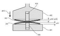
- FIG. 15 is a front sectional view showing a state in which the central portion of the bent substrate is abutted against the upper substrate.
- the bonding surface of the substrate 301 and the bonding surface of the substrate 302 are butted at the center.
- the stage 402 is moved to the lower stage 401 side along the Z direction in the Z direction elevating drive mechanism 406 of the stage drive mechanism 404.
- the substrate 301 held on the stage 401 in a state where the central portion 301 c is bent so as to be convex upward is abutted against the substrate 302 held on the upper stage 402.
- the bonding surface of the substrate 301 and the bonding surface of the substrate 302 are abutted at the center.
- the bonding surface between the substrate 301 and the bonding surface of the substrate 302 is terminated with a hydroxyl group (OH group) on the bonding surface by hydrophilization treatment ( M-OH) layer is interposed.
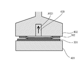
- FIG. 16 is a diagram for explaining a center push bonding method of pushing out the central portion of the substrate from above.
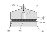
- FIG. 17 is a diagram illustrating the center push bonding method according to the present embodiment.
- 18A and 18B are diagrams illustrating a method of calibrating the parallelism and gap of the stage in units of microns. Specifically, a laser sensor (not shown) is provided for the stage and head described in FIG. Then, the size of three gaps (A, B, C) between the stage 401 and the stage 402 is measured with a laser, and the distance G1 is obtained to read the parallel deviation and the gap error. Based on the read result, the stage 402 is feedback-corrected by using the protruding mechanism 412 so that the parallelism and gap are set in advance. Actually, calibration can be performed every day in a necessary situation by pressing a calibration button (not shown) linked to these devices.
- FIG. 19 is a diagram for explaining a method of adjusting the gap by correcting the wafer thickness variation.
- the wafer thickness measuring means the wafer thickness of the substrates 301 and 302 is measured at three locations with a laser from above and below at the aligner position.
- the substrate bonding apparatus 100 moves so as to keep the specified gap between the stage 401 and the stage 402 before the new substrates 301 and 302 are inserted, three gaps between the stage 401 and the stage 402 (A , B, C) are measured to determine the distance G1.
- the distance G2 between the substrates 301 and 302 is automatically calculated from the wafer thicknesses t1 and t2 of the substrates 301 and 302 and the distance G1 between the stage 402 and the stage 401 measured in advance with the substrates 301 and 302 actually inserted and held. And feed back to the Z-axis. By doing so, a marginal alignment gap and zero point release can be achieved. Further, the laser measurement positions on the stages 401 and 402 may not be three points. One point is also acceptable. Further, it may not be performed every time the wafer is replaced, but may be performed in a timely manner or a specified number of times.
- a temporary bonding step for temporarily bonding the substrates 301 and 302 to each other is executed (step S104-2).
- the Z-direction lifting drive mechanism 406 is driven to lower the stage 402, and at least one substrate 301 is moved.
- 302 is applied with a pressure below a certain value or a pressure below a critical pressure.
- the application of pressure may be started simultaneously with the contact, or may be started after a certain time has elapsed after the contact. Moreover, the application of pressure may be performed over a part of time in the contact state, or may be performed over the whole.
- the application of pressure may be performed intermittently, and a constant pressure may be maintained during application, or may be changed with time.
- a constant pressure may be maintained during application, or may be changed with time.
- it can bond on the whole surface. If it is pushed in until it is completely pasted, pressure is applied and shifts, so it is not limited to the position where the entire surface is pressed.
- the critical pressure of the joint surface can be defined as a pressure at which a desired characteristic of the joint surface is changed or lost when the joint surface is pressed with a pressure exceeding that. For example, if too much pressure is applied to the bonding surface in the contact step (temporary bonding) before the step of finally forming the bonding interface (main bonding), the substrates 301 and 302 cannot be bonded and separated. Alternatively, it may be separated, and even if contact is made again and pressure is applied, desired bonding may not be possible.
- the substrates 301 and 302 that are in contact with each other can be separated while the substrates 301 and 302 remain in a non-bonded state without impairing surface characteristics for performing desired bonding. Can do.
- the lowest pressure at which the substrates 301 and 302 can be separated thereafter may be defined as the critical pressure.
- the separation can be made.
- characteristics such as desired bonding strength cannot be obtained even if a joining step is performed thereafter.
- the substrates 301 and 302 may be separated with a relatively small force.
- surface properties deteriorate due to destruction of the strongly formed bonding interface due to the separation, and as a result, desired bonding characteristics cannot be finally obtained.
- the critical pressure may be defined as a pressure at which a desired bonding cannot be performed when a pressure higher than that is applied, and a pressure at which a desired bonding cannot be performed when a pressure exceeding the critical pressure is applied. Also good.
- the critical pressure can be determined according to various factors such as the material forming the joint surface, the presence or absence of a surface layer on the joint surface, the characteristics of the surface layer, and the surface energy. Therefore, the bonding method of the present application may include a step (not shown) of determining the critical pressure of the bonding surface of at least one of the substrates 301 and 302 before the temporary bonding step (step S104-2). .
- the pressure applied in the temporary bonding step (step S104-2) is preferably equal to or lower than the critical pressure of the smaller critical pressure defined on both bonding surfaces of the substrates 301 and 302. Thereby, it is possible to ensure that an appropriate pressure is applied to any joint surface of the substrates 301 and 302. In the case where the critical pressure is not defined on one joint surface, a pressure that is equal to or lower than the critical pressure of the other joint surface on which the critical pressure is defined may be applied.
- a relative position measurement step (position shift amount measurement step) is executed (step S104-3).
- the position measuring means 500 uses the images (image data) GA relating to the transmitted light and reflected light of the illumination light emitted from the respective coaxial illumination systems of the cameras 501 and 502 to be attached to both the substrates 301 and 302. Further, the positions of the respective marks (MK1a, MK2a) and (MK1b, MK2b) are recognized.
- the controller 700 determines the amount of positional deviation ( ⁇ xa, ⁇ ya) ( ⁇ xb) between the marks (MK1a, MK2a), (MK1b, MK2b). , ⁇ yb).
- the relative position of the bonding surfaces of the substrates 301 and 302 is measured in a state under contact pressure
- the relative position of the bonding surfaces is the final bonding state in a state where contact and pressure are applied. Get closer to. For this reason, a more accurate and uniform contact state can be formed or maintained by pressurization.
- step S104-4 a determination step for determining whether or not the relative positional deviation amount is within the allowable error range is executed (step S104-4). Whether or not the positional deviation amount is within a predetermined allowable error range satisfies the condition that all the three positional deviation amounts ( ⁇ x, ⁇ y, ⁇ ) are within the respective allowable error ranges. It may be determined based on whether or not.
- a corrected movement amount calculation step is executed (step S104-5).
- the correction movement amounts of the substrates 301 and 302 are determined.
- the correction movement amounts of the substrates 301 and 302 for moving from the relative position measured in the relative position measurement step (step S104-3) to the desired relative position are obtained.
- the controller 700 selects desired values of both substrates 301 and 302 based on the positional deviation amounts ( ⁇ xa, ⁇ ya) and ( ⁇ xb, ⁇ yb) of the two sets of marks (MK1a, MK2a) and (MK1b, MK2b).
- a relative deviation amount ⁇ D (specifically ⁇ x, ⁇ y, ⁇ ) in the X direction, Y direction, and ⁇ direction from the position is calculated.
- the controller 700 finally adjusts the substrates 301 and 302 to the correction amounts ⁇ D ( ⁇ x, ⁇ y, and ⁇ ) corresponding to the relative deviation amounts ⁇ D ( ⁇ x, ⁇ y, ⁇ ) between the substrates 301 and 302.
- the movement path may be formed so that the bonding surfaces are brought into contact again with the relative movement of 302. That is, in the following relative position measurement step (step S104-3), the bonded surfaces that have been in contact with each other or the substrates 301 and 302 that have been in contact with each other are separated and contacted again after the movement of the correction movement amount. Further, from the relative position measured in the relative position measurement step, the pressure in the contact state of the joint surface is once removed or reduced, and the substrates 301 and 302 remain in contact with each other at the center.
- the movement path may be formed by relatively moving the substrates 301 and 302 in a direction substantially parallel to the bonding surface and pressurizing again. The formation of the above movement path is an example, and the present invention is not limited to this.
- the corrected movement amount may be determined as a function of a predetermined parameter.
- the measured relative positions of the substrates 301 and 302 are preferably one parameter that is taken into account by the function.
- the parameters of the function may include parameters other than the relative positions of the measured substrates 301 and 302.
- the movement paths of the substrates 301 and 302 for correcting the relative position can take various shapes, and therefore, the habits and errors of the movement mechanism or measurement mechanism of the substrates 301 and 302 at that time are considered as parameters. May be.
- a release process is performed in which the substrates 301 and 302 temporarily bonded to each other are released from each other (step S104-6).
- this release step the distance between the outer peripheral portion 301 s of the substrate 301 and the outer peripheral portion 302 s of the substrate 302 is increased in a state where the central portions of the substrates are abutted so as to maintain a certain distance. Return the deflection.
- a position correction process for correcting the relative positions of the substrates 301 and 302 is executed (step S104-7).
- the substrates 301 and 302 are moved by the correction movement amount determined in the correction movement amount calculation step (step S104-5).
- the substrates 301 and 302 are moved according to the obtained movement route. Thereby, the measured misalignment is corrected or minimized.
- the controller 700 instructs the drive mechanisms 403 to 407 of the stages 401 and 402 to move both the substrates 301 and 302 according to the correction path calculated in the correction movement amount calculation step (step S104-5). Put out.
- the stage driving mechanisms 403 and 404 drive the stage 402 in two translational directions (X direction and Y direction) and a rotational direction ( ⁇ direction) in accordance with an instruction from the controller 700, whereby both substrates 301 and 302 are driven. Are relatively moved, and the positional deviation amount ⁇ D is corrected.
- the movement of the substrates 301 and 302 includes a movement path in a state in which the substrates 301 and 302 are separated from each other, the joint surfaces are brought into contact with each other at the center and brought into contact again.
- the substrates 301 and 302 move while maintaining the contact state without separating the substrates 301 and 302 or the bonding surfaces, the substrates 301 and 302 are brought into contact with each other at the center when the movement is completed. A contact state is realized.
- step S104-7 the process returns to the step of bending the substrate 301 (step S103). Then, the position correction process (step S104-7) is repeated from the matching process (step S104) of the substrates 301 and 302 until the measured displacement amount of the substrates 301 and 302 falls within the allowable error range. Accordingly, it is possible to perform positioning between the substrates 301 and 302 with high accuracy and finally form a bonding interface or a bonding interface having high positioning accuracy between the substrates 301 and 302.
- step S104-4 a bonding step of bonding the substrates 301 and 302 to each other is executed (step S105).
- the bonding step first, the projecting mechanism 430 is immersed in the stage 402 as indicated by an arrow AR21 in FIG. Note that “depress the protrusion mechanism 430 into the stage 402” means that the pressing member 434 of the protrusion mechanism 430 is inserted into the stage 402 in detail.
- the substrates 301 and 302 maintain a state in which the central portions thereof are in contact with each other with a pressure that maintains a non-bonded state.
- the upper stage 402 is moved in a direction approaching the lower stage 401 by the Z-direction lifting drive mechanism 406.
- the substrate 302 is pressed against the substrate 301, the distance between the outer peripheral portion of the substrate 301 and the outer peripheral portion of the substrate 302 is reduced, and the substrates 301 and 302 are bonded to each other over the entire surface.
- the distance between the central portion of the substrate 301 and the central portion of the substrate 302 may be maintained by immersing the protruding mechanism 430 into the stage 402. Even in this case, by moving the upper stage 402 toward the lower stage 401, the distance between the outer peripheral portion of the substrate 301 and the outer peripheral portion of the substrate 302 is reduced, and the substrates 301 and 302 are overlapped with each other. Become.
- the so-called center push method in which the substrates 301 and 302 are bent by both the stages 401 and 402 is adopted.
- the bonding step as shown by arrows AR23 and AR24 in FIG.
- the substrates 301 and 302 maintain a state in which the central portions thereof are in contact with each other with a pressure that maintains a non-bonded state.
- the upper stage 402 is moved in a direction to approach the lower stage 401 by the Z-direction lifting drive mechanism 406.
- the substrate 302 is pressed against the substrate 301, the distance between the outer peripheral portion of the substrate 301 and the outer peripheral portion of the substrate 302 is reduced, and the substrates 301 and 302 are brought into contact with each other over the entire surface.
- a holding means such as a vacuum chuck for holding the substrate 302 is released, and then the vacuum suction of the lower stage 401 is operated and the lower side is operated. If the center portion of the substrate 301 is bent, the bending is also restored. Thereafter, it is preferable that the upper stage 402 is raised by the Z-direction lift drive mechanism 406.
- step S106 the bonding process of the substrates 301 and 302 is performed (step S106).
- bonding is performed after the bonding surface of the substrate 301 and the bonding surface of the substrate 302 are abutted on the entire surface.
- pressure may be applied to the bonding surfaces in which the bonding surfaces of the substrates 301 and 302 are in contact with each other.
- the pressure applied in a state where the bonding surfaces of the substrates 301 and 302 are abutted on the entire surface is preferably a pressure equal to or higher than the critical pressure or a pressure exceeding the critical pressure.
- the pressurization in a state where the bonding surfaces of the substrates 301 and 302 are abutted on the entire surface is mechanically applied to the substrates 301 and 302 by using a mechanism such as the Z-direction lifting drive mechanism 406 of the substrate bonding apparatus 100, for example. Can be added.
- the pressurization in a state where the bonding surfaces of the substrates 301 and 302 are in contact with each other gives an opposite charge to the substrates 301 and 302. You may add with respect to the board
- the pressurization mode, method, pressure, and the like in a state where the bonding surfaces of the substrates 301 and 302 are abutted on the entire surface are not limited to the above examples, and are appropriately adjusted according to various specific substrate bonding methods. May be.
- the bonding step may include a step of applying heat to the bonding surface in which the bonding surfaces of the substrates 301 and 302 are abutted on the entire surface.
- a bonding interface having desired characteristics can be formed.
- You may form the joining interface which finally has a desired characteristic by heating.
- the unnecessary surface layer existing on the surface of the bonding surface is finally diffused and removed, forming a bonding interface where the new surface directly contacts. It is possible to reduce the microscopic surface irregularities and increase the area of the substantial bonding interface. Thereby, various characteristics such as mechanical characteristics, electrical characteristics, and chemical characteristics of the bonding interface can be improved. Heating can be performed simultaneously with the above pressurization.
- heating and pressurization so that heating time and pressurization time may overlap a part or all.
- the electrostatic attraction due to this charge is used to electrically
- the substrates 301 and 302 may be heated while being pressed. Thereby, what is called anodic bonding can be performed.
- Heating may be performed by conducting heat from the stages 401 and 402 that support the substrates 301 and 302, or by conducting heat from the gas by heating the gas in the atmosphere of the substrates 301 and 302. It may be performed by irradiating the joint surface with light or the like.
- the final bonding interface between the substrates 301 and 302 may be formed by heating the bonding surfaces of the substrates 301 and 302 together with pressure. In this way, both substrates 301 and 302 are well aligned and final bonding is achieved.
- a step of performing a hydrophilization treatment for attaching water or an OH-containing substance to the surfaces of the bonding surfaces of the substrate 301 and the substrate 302 The substrate 302 is disposed with the bonding surfaces facing each other, the substrate 301 is bent with respect to the outer peripheral portion 301 s of the bonding surface so that the central portion 301 c protrudes toward the substrate 302, and the bonding of the substrate 301 is performed.
- the outer peripheral portion 301 s of the substrate 301 and the outer peripheral portion 302 s of the substrate 302 are in a state in which the surface and the joint surface of the substrate 302 are abutted with each other at a central portion, and in a state where the central portions are abutted with each other with a pressure that maintains a non-bonded state. , And the bonding surface of the substrate 301 and the bonding surface of the substrate 302 are abutted and bonded to each other. Thereby, it is possible to prevent the generation of voids between the substrates 301 and 302 and to perform bonding with high positional accuracy.
- the atmosphere around the substrate 302 and the substrate 301 may be evacuated before the substrates 301 and 302 are bonded to each other.
- the process of aligning the substrate 301 and the substrate 302 is performed in the atmosphere.
- the bonding surface of the substrate 301 and the bonding surface of the substrate 302 are brought into contact with each other at the center, a state in which water molecules are interposed between the bonding surface of the substrate 301 and the bonding surface of the substrate 302 is maintained. .
- the OH groups are not bonded to each other, and the substrates 301 and 302 can be peeled off without affecting the bonding surfaces.
- the step of abutting the bonding surface of the substrate 301 and the bonding surface of the substrate 302 at the center portion is performed in a vacuum, water molecules do not remain sufficiently on the bonding surface. When peeled off, the joint surface will be affected.
- the bonding surface of the substrate 301 and the bonding surface of the substrate 302 are not bonded, and the alignment between the substrate 301 and the substrate 302 can be repeatedly performed.
- the surrounding atmosphere is evacuated, so that the intermediate surface is interposed between the bonding surface of the substrate 302 and the bonding surface of the substrate 301. It is possible to prevent air from being mixed into the water. Therefore, voids can be prevented from occurring at the joint between the substrate 302 and the substrate 301. As a result, it is possible to bond the substrates 301 and 302 with high quality while aligning the substrates 301 and 302 with high accuracy.
- the positional deviation amount between the substrate 302 and the substrate 301 is set in a state where the bonding surface of the substrate 302 and the bonding surface of the substrate 301 are abutted at the center. If the measured positional deviation amount exceeds the allowable error range, the relative position between the substrate 301 and the substrate 302 is adjusted so that the positional deviation amount between the substrate 302 and the substrate 301 is reduced, and the position The measurement of the positional deviation amount between the substrate 301 and the substrate 302 and the adjustment of the relative position between the substrate 301 and the substrate 302 were repeated until the deviation amount was within the allowable error range. In this manner, the substrate 301 and the substrate 302 can be aligned with high accuracy by repeating until the positional deviation amount between the substrate 301 and the substrate 302 is within the allowable error range.
- the step of measuring the amount of positional deviation between the substrate 301 and the substrate 302 is performed in a state in which the bonding surface of the substrate 301 and the bonding surface of the substrate 302 are brought into contact with each other at a pressure or time that maintains the non-bonded state between the central portions. I made it.
- the substrate 301 and the substrate 302 are brought into contact with each other with an excessive pressure or left for a long time, water interposed between the bonding surface of the substrate 301 and the bonding surface of the substrate 302 is expelled, and the substrate 301 and the substrate 302 are discharged. May be joined.
- the pressure at which the substrate 301 and the substrate 302 are maintained in a non-bonded state in other words, maintaining a state in which water is interposed between the bonded surface of the substrate 301 and the bonded surface of the substrate 302,
- the alignment between the substrate 301 and the substrate 302 can be performed smoothly.
- the substrate 301 is formed into a flat plate shape so as to abut against the bonding surface of the substrate 302.
- the bonding surface of the substrate 301 and the bonding surface of the substrate 302 can be easily butted together and bonded together.
- the substrates 301 and 302 can be reliably bonded by pressurizing and bonding the substrate 301 and the substrate 302. .
- the step of abutting the first substrate and the second substrate is performed in a state in which the first substrate and the second substrate are abutted at a pressure that maintains a non-bonded state.
- the distance between the outer peripheral portion of the second substrate and the outer peripheral portion of the second substrate is reduced, and the bonding surface of the first substrate and the bonding surface of the second substrate are butted together and bonded.
- the alignment adjustment can be performed again by not increasing the pressure at which the substrates 301 and 302 are bonded to each other.
- the substrate bonding method in which the substrate warpage amount measuring step for measuring the warpage amount of the substrates 301 and 302 held on the stages 401 and 402 is performed immediately before the alignment step (see step S102 in FIG. 14).
- the center portions of the substrates 301 and 302 held on the stages 401 and 402 may be warped in a protruding manner.
- the distance between the central portions of the substrates 301 and 302 is shorter than the distance G2 obtained by subtracting the thickness of the substrates 301 and 302 from the distance G1 between the stages 401 and 402.
- the central portions of the substrates 301 and 302 are warped so as to protrude.
- the distance between the central portions of the stages 401 and 402 becomes shorter than the desired distance. Therefore, for example, when the total amount of warpage of the central portions of the substrates 301 and 302 is 10 ⁇ m or more, the substrates 301 and 302 come into contact with each other when the stages 401 and 402 are brought closer to each other so that the distance G2 becomes 10 ⁇ m. The process cannot be performed.
- the substrate bonding apparatus includes a displacement sensor 435 that detects the position of the protruding mechanism 430 (the position of the pressing member 434 of the protruding mechanism 430), similarly to the substrate bonding apparatus 100 according to the embodiment.
- the displacement sensor 435 projects the protrusion mechanism 430 on a flat reference substrate (not shown) without warpage.
- the position detecting step is detected at the position of the protrusion mechanism 430 in a state where the protrusion mechanism 430 is in contact with the substrate 301 and 302 at a very small pressure. A certain protruding mechanism position is detected (position detecting step).
- the position of the protrusion mechanism 430 in a state where the contact is made with a pressure having no magnitude is detected.
- substrate joining apparatus calculates the curvature amount p1, p2 from the stage 401,402 of the board
- the warpage amounts p1 and p2 of the substrates 301 and 302 from the stages 401 and 402 are calculated from the difference between the first protrusion mechanism position and the second protrusion mechanism position. Then, the stage 402 is brought closer to the stage 401 so that a distance G3 obtained by subtracting the warpage amounts p1 and p2 from the distance G2 becomes a desired distance.
- the alignment operation of the substrates 301 and 302 may be performed in a state where the stage 402 is brought close to the stage 401 so that the distance G3 becomes a desired distance.
- an insulating film such as an oxide film or a nitride film is formed on the bonding surface side of the substrates 301 and 302.
- an insulating film is formed only on the bonding surface side (only one side) of the substrates 301 and 302, the substrates 301 and 302 warp so as to protrude toward the bonding surface on which the insulating film is formed.
- an insulating film formed on the bonding surface side of both the substrates 301 and 302 is formed by a CVD (Chemical Vapor Deposition) method.
- the substrates 301 and 302 warp so as to be convex on one side which is a bonding surface thereof.
- CMP Chemical Mechanical Polishing
- the method for calculating the warpage amount is not limited to this method, and the other substrates 301 and 302 are calculated.
- a method of calculating the amount of warpage may be employed. For example, in the step of measuring the thickness of the substrates 301 and 302, the amount of warpage of the substrates 301 and 302 may be measured using a laser distance meter.
- the substrates 301 and 302 may be bent as shown in FIG.
- the larger one of the warpage amount (first warpage amount) of the substrate 301 and the warpage amount (second warpage amount) of the substrate 302 is specified.
- 302 may be bent so that the warpage amounts of the respective warpages are equal to or more than the specified warpage amount.
- the amount of warping of the substrate 301 is the amount of warping of the central portion 301 c of the substrate 301 toward the substrate 302
- the amount of warping of the substrate 302 is the amount of warping of the central portion 302 c of the substrate 302 toward the substrate 301.
- the substrate bonding apparatus when the warp amount p11 of the substrate 301 is larger than the warp amount p12 of the substrate 302, the substrate bonding apparatus according to this modification first has a large warp amount in the step of bending the substrate.
- the warp amount p11 of the substrate 301 is specified.
- the substrate bonding apparatus determines the position of the protruding mechanism 430 in a state where the protruding mechanism 430 is brought into contact with the substrates 301 and 302 with such a pressure that the substrates 301 and 302 do not bend.
- the warpage amounts p11 and p12 of the substrates 301 and 302 from the stages 401 and 402 are calculated.
- the substrate bonding apparatus bends the central portion 302c of the substrate 302 so that the warpage amount of the substrate 302 becomes equal to the specified warpage amount of the substrate 301 (see arrow AR61 in FIG. 23B). Thereafter, the substrate bonding apparatus executes a process of abutting the substrates 301 and 302 (step S104 in FIG. 14).
- the temporary bonding step and the bonding step are performed. Therefore, the two substrates 301 and 302 bonded to each other are performed. The amount of warpage can be reduced.
- the protrusion mechanism (first protrusion) that contacts the substrate 301 so that the warpage amount of the central portion of the substrate 301 is equal to the warpage amount of the central portion of the substrate 302.
- the protruding mechanism position of the protruding mechanism (second protruding mechanism) 430 to be brought into contact with 430 or the substrate 302 may be controlled.
- the substrate bonding apparatus causes the substrate 301 and the substrate 302 to approach each other (see arrows AR71 and AR72 in FIGS. 24A and 24B).
- the protrusion mechanism position of the protrusion mechanism 430 brought into contact with the central portion 302c of the substrate 302 is controlled so that the warp amount p13 (p15) of 301 is equal to the warp amount p14 (p16) of the substrate 302.
- the substrate bonding apparatus controls the protrusion mechanism 430 that is in contact with the substrate 301 so that the pressure by which the substrate 301 is pressed by the protrusion mechanism 430 is constant at a preset pressure. That is, when the substrate bonding apparatus lowers the stage 402 in the direction approaching the stage 401, the position of one of the two protruding mechanisms 430 is controlled, and the pressure of the other protruding mechanism 430 is controlled.
- the protruding mechanism 430 includes a voice coil motor 433, a pressing member 434, and a displacement sensor 435 as shown in FIG. In this case, the protrusion mechanism 430 controls the position of the pressing member 434 based on the detection value detected by the displacement sensor 435.
- the protrusion mechanism position of the protrusion mechanism 430 that is brought into contact with each other may be controlled.
- the bonding process is performed in a state where the warpage amounts of the substrates 301 and 302 are always equal, so that the warpage amounts of the two substrates 301 and 302 bonded to each other can be reduced.
- the relative positional relationship between the two substrates 301 and 302 temporarily bonded to each other is measured in the relative position measurement step (step S104-3), and the position correction step (step S104-7). ), The example in which the substrates 301 and 302 are moved by the correction movement amount determined in the correction movement amount calculation step (step S104-5) has been described.
- the relative position measurement step the amount of positional deviation in the rotational direction around the other XY direction or Z axis with respect to one of the two substrates 301 and 302 is measured.
- the XY direction corresponds to a direction orthogonal to the Z direction in which the stages 401 and 402 face each other as described above.
- the type of the amount of displacement measured in the relative position measurement process is not limited to these.
- a positional deviation amount corresponding to the warpage amount with respect to the outer peripheral portion of the central portion of the substrates 301 and 302 temporarily bonded to each other may be measured. If the measured displacement amount exceeds the allowable error range, the substrate 301, so that the displacement amount corresponding to the warpage amount is reduced in the step of bending the substrate after the release step is executed.
- Each of 302 may be bent.
- the substrate bonding apparatus performs a distance and thickness measurement process and a hydrophilization process (steps S200 and S201).
- the processes in steps S200 and S201 are the same as the processes in steps S100 and S101 described in the embodiment.
- the substrate bonding apparatus executes a step of bending the substrate (step S202).
- the substrate bonding apparatus specifies the larger amount of warpage between the warpage amount of the substrate 301 and the warpage amount of the substrate 302, and the warpage amounts of the respective substrates 301 and 302 are determined as the specified warpage amount.
- substrates 301 and 302 is bent so that it may become above.
- the substrate bonding apparatus performs an alignment process, a substrate matching process, and a temporary bonding process (steps S203, S204, and S205).
- the processing in steps S203 to S205 is the same as the processing in steps S102, S104, and S104-2 described in the embodiment.
- the substrate bonding apparatus executes a relative position measurement process (step S206).
- the substrate bonding apparatus has a positional displacement amount in the rotational direction around the other XY direction or Z axis with respect to one of the two substrates 301 and 302, and the outer peripheral portion of the central portion of the substrates 301 and 302 that are temporarily bonded to each other.
- the positional deviation amount corresponding to the warpage amount is measured.
- the substrate bonding apparatus includes a distance LM1 between the centers of two alignment marks MK1a and MK1b provided on the substrate 301, and two alignment marks MK2a provided on the substrate 302. A distance LM2 between the centers of MK2b is calculated.
- the substrate bonding apparatus measures the amount of displacement according to the amount of warpage of the substrates 301 and 302 that are temporarily bonded to each other by calculating the difference between the calculated distances LM1 and LM2.
- the distance LM1 between the alignment marks MK1a and MK1b of the substrate 301 is longer than the distance LM2 between the alignment marks MK2a and MK2b of the substrate 302, they are temporarily joined together as shown in FIG.
- the substrates 301 and 302 are warped so as to be convex toward the substrate 302 side.
- the difference between the distance LM1 and the distance LM2 becomes longer as the warpage amount of the substrates 301 and 302 temporarily bonded to each other is larger.
- the substrate bonding apparatus responds to the relative positional deviation amount of the two substrates 301 and 302 in the XY direction or the rotation direction around the Z axis and the warpage amount of the temporarily bonded substrates 301 and 302. It is determined whether or not the relative positional deviation amount is within an allowable error range (step S207).
- the substrate bonding apparatus determines that the relative positional deviation amount is within the allowable error range (step S207: Yes)
- the substrate bonding apparatus executes a bonding process and a bonding process (steps S212 and S213).
- the processing in steps S212 and S213 is the same as the processing in steps S105 and S106 described in the embodiment.
- step S208 when the substrate bonding apparatus determines that the relative positional deviation amount exceeds the allowable error range (step S207: No), it executes a correction movement amount / warpage amount calculation step (step S208).
- a desired position is calculated from the relative position measured in the relative position measurement step (step S104-3) in the same manner as the correction movement amount calculation step (step S104-5) described in the embodiment.
- the correction movement amount of the substrates 301 and 302 for moving to the relative position is calculated.
- the substrate bonding apparatus determines the warpage amount of each of the substrates 301 and 302 in the substrate abutting step (step S204) for abutting the substrates 301 and 302 together.
- the substrate bonding apparatus includes a protrusion amount of the protrusion mechanism (first protrusion mechanism) 430 that presses the substrate 301 and a protrusion mechanism (second protrusion mechanism) that presses the substrate 302 in the substrate matching step.
- the protrusion amount of 430 is set.
- the substrates 301 and 302 are brought into contact with each other in a state where the warp amount p21 of the substrate 301 and the warp amount p22 of the substrate 302 are equal, and then temporarily joined.
- FIG. 27B it is assumed that the two substrates 301 and 302 temporarily bonded to each other are warped in a convex shape toward the substrate 302 side.
- the distance LM2 between the centers of the alignment marks MK1a and MK1b on the substrate 301 is shorter than the distance LM1 between the centers of the alignment marks MK2a and MK2b on the substrate 302. In this case, as shown in FIG.
- the substrate bonding apparatus protrudes to press the central portions 301c and 302c of the substrates 301 and 302 so that the warp amount p22 of the substrate 302 is longer than the warp amount p21 of the substrate 301.
- the protrusion amount of the mechanism 430 is set. For example, when the substrates 301 and 302 are abutted and temporarily bonded in a state where the warp amount p21 of the substrate 301 and the warp amount p22 of the substrate 302 are both set to 15 ⁇ m, the substrates 301 and 302 temporarily bonded to each other are shown in FIG. Suppose you warp as shown.
- the substrate bonding apparatus sets the protrusion amount of each protrusion mechanism 430 so that the warp amount p21 of the substrate 301 is 13 ⁇ m and the warp amount p22 of the substrate 302 is 17 ⁇ m, for example.
- FIG. 28A when the substrates 301 and 302 are brought into contact with each other in a state where the warping amounts p21 and p22 of the substrates 301 and 302 are equal to each other and temporarily joined, as shown in FIG. Suppose that it is warped in a convex shape.
- the distance LM2 between the centers of the alignment marks MK1a and MK1b on the substrate 301 is longer than the distance LM1 between the centers of the alignment marks MK2a and MK2b on the substrate 302. In this case, as shown in FIG.
- the substrate bonding apparatus projects the center portions 301c and 302c of the substrates 301 and 302 so that the warp amount p21 of the substrate 301 is longer than the warp amount p22 of the substrate 302.
- the protrusion amount of the mechanism 430 is set. For example, when the substrates 301 and 302 are abutted and temporarily bonded in a state where the warp amount p21 of the substrate 301 and the warp amount p22 of the substrate 302 are both set to 15 ⁇ m, the substrates 301 and 302 temporarily bonded to each other are shown in FIG. Suppose you warp as shown. In this case, the substrate bonding apparatus sets the protrusion amount of each protrusion mechanism 430 so that the warp amount p21 of the substrate 301 is 17 ⁇ m and the warp amount of the substrate 302 is 13 ⁇ m, for example.
- the substrate bonding apparatus determines the protrusion amount of the protrusion mechanism 430 that presses each of the substrates 301 and 302 according to the warpage amount of the central portions 301c and 302c of the substrates 301 and 302 that are temporarily bonded to each other with respect to the outer peripheral portions 301s and 302s. It is set based on the correlation between the amount of misalignment and the amount of protrusion of the protrusion mechanism 430 that presses each of the substrates 301 and 302.
- the substrate bonding apparatus calculates the correlation between the amount of displacement according to the amount of warpage of the substrates 301 and 302 temporarily bonded to each other and the amount of protrusion of the protrusion mechanism 430 that presses each of the substrates 301 and 302.
- the correlation data shown may be held in advance.
- the substrate bonding apparatus refers to the correlation data held in advance, and determines each of the substrates 301 and 302 from the amount of displacement according to the amount of warpage of the substrates 301 and 302 temporarily bonded to each other calculated in the relative position measurement step.
- the protrusion amount of the protrusion mechanism 430 to be pressed is set.
- the substrate bonding apparatus acquires correlation data by measuring the amounts of warpage of the substrates 301 and 302 that are temporarily bonded to each other while changing the protruding amount of the protruding mechanism 430 that presses the substrates 301 and 302 in advance. What should I do?
- the substrate bonding apparatus is a relational expression showing a correlation between the amount of displacement according to the amount of warpage of the substrates 301 and 302 temporarily bonded to each other and the amount of protrusion of the protrusion mechanism 430 that presses each of the substrates 301 and 302. May be stored in advance.
- the substrate bonding apparatus determines that the amount of displacement according to the amount of warpage of the central portions 301c and 302c of the substrates 301 and 302 temporarily bonded to the outer peripheral portions 301s and 302s exceeds the allowable error range, You may make it change the protrusion amount of the protrusion mechanism 430 which presses 301,302 only by the unit amount set beforehand.
- the substrate bonding apparatus performs a substrate releasing step and a position correcting step (steps S209 and S210).
- steps S209 and S210 are the same as the processes in steps S104-6 and S104-7 described in the embodiment.
- the substrate bonding apparatus executes a step of bending the substrates 301 and 302 based on the protrusion amount of the protrusion mechanism 430 that presses the substrates 301 and 302, respectively, set in the above-described correction movement amount / warpage amount calculation step. (Step S211). Then, the substrate bonding apparatus executes the process of step S204 again. Then, the step of bending the substrate, the substrate matching step, the relative position measurement step, the correction movement amount / warpage amount calculation step, the substrate release step and the position until the positional deviation amount of the substrates 301 and 302 falls within the allowable error range. The correction process is repeated.
- the bonding process is performed after the positional deviation amount corresponding to the warpage amount of the substrates 301 and 302 temporarily bonded to each other falls within the allowable error range.
- the amount of warpage 302 can be greatly reduced.
- the warpage amount of each substrate in the substrate matching step which is set at the time of bonding of one substrate among the bonding of the substrates repeatedly performed a plurality of times, You may make it set as the curvature amount of each board
- gas may be blown into the gap between the peripheral portion of the substrate 301 and the peripheral portion of the substrate 302 in the direction from the peripheral edge of the substrates 301 and 302 toward the central portion of the substrates 301 and 302. .
- the stages 401 and 402 according to this modification have a holding mechanism 3440 that holds the substrates 301 and 302 and a protrusion that bends the substrates 301 and 302 by pressing the central portion of the substrates 301 and 302. And a mechanism 430.
- the holding mechanism 3440 includes a vacuum chuck having a plurality (four in FIG. 29) of annular suction portions 3440a, 3440b, 3440c, and 3440d.
- the adsorption portions 3440a, 3440b, 3440c, and 3440d have different diameters and are arranged concentrically.
- the substrates 301 and 302 are held on the stages 401 and 402 while being sucked by the suction portions 3440a, 3440b, 3440c, and 3440d.
- the suction portions 3440a and 3440b are opposed to the central portions of the substrates 301 and 302
- the suction portions 3440c and 3440d are opposed to the peripheral portions of the substrates 301 and 302.
- the adsorption units 3440a, 3440b, 3440c, and 3440d can take a state of adsorbing the substrates 301 and 302 and a state of not adsorbing the substrates.
- the suction portions 3440a and 3440b disposed relatively inside the stages 401 and 402 are not vacuum-sucked, and the suction portions 3440c and 3440d disposed relatively outside the stages 401 and 402 are vacuum-sucked.
- the radius L1 of the suction part 3440a located closest to the center C1 of the stages 401, 402 the distance L2 between the suction part 3440a and the suction part 3440a adjacent to the outside on the outside, the suction part 3440b and the suction part.
- the fixed positions of the substrates 301 and 302 are determined by the distance L3 between the adsorbing portion 3440c adjacent to the outer side 3440b and the distance L4 between the adsorbing portion 3440c and the outermost adsorbing portion 3440d.
- the substrate 301 is bent such that the central portion 301c protrudes toward the substrate 302 with respect to the outer peripheral portion 301s of the joint surface.
- the two suction portions 3440c and 3440d on the peripheral side of the stage 401 suck the substrate 301, while the two suction portions 3440a and 3440b on the central side of the stage 401 stop sucking the substrate 301 (FIG. (See arrows AR41 and AR42 of 30A).
- the stages 401 and 402 hold the substrates 301 and 302 at two suction positions (holding positions) at different distances from the center of the substrates 301 and 302 in the peripheral portions of the substrates 301 and 302.
- the substrate 302 is bent such that the central portion 302c protrudes toward the substrate 301 with respect to the outer peripheral portion 302s of the bonding surface.
- the two suction portions 3440c and 3440d on the peripheral side of the stage 402 suck the substrate 302, while the two suction portions 3440a and 3440b on the center side of the stage 402 stop sucking the substrate 302 (FIG. (See arrows AR41 and AR42 of 30A).
- the stage 402 is raised and the gap between the substrates 301 and 302 is widened, and the protruding mechanism 430 of the stage 401 is immersed in the stage 401 (see FIG. 30B).
- 30B) see arrow AR51 in FIG. 30B
- the projection mechanism 430 of the stage 402 moves in the direction in which the stage 402 is immersed (see arrow AR52 in FIG. 30B).
- the rising speed of the stage 402 is controlled so that the tensile pressure of the substrate 302 when the substrate 302 is peeled off from the substrate 301 is constant.
- the suction portions 3440a and 440b on the center side of the stage 401 and the suction portions 3440a and 3440b on the center side of the stage 402 resume suction of the substrates 301 and 302 (see arrows AR61 and AR62 in FIG. 30B).
- the timing at which the suction units 3440a and 3440b resume the suction of the substrates 301 and 302 is such that the protrusion mechanism 430 of the stage 401 is immersed in the stage 401 while the gap between the substrates 301 and 302 is widened, and the protrusion mechanism of the stage 402 430 may be the timing before and after the timing of immersing the stage 402, or may be simultaneous.
- the blower 3811 blows gas in the gap between the peripheral portion of the substrate 301 and the peripheral portion of the substrate 302 in the direction from the peripheral edge of the substrates 301 and 302 toward the central portion of the substrates 301 and 302 (FIG. 30B). (See arrow AR6).
- a force in a direction in which the substrate 302 is peeled off from the substrate 301 is generated from the differential pressure between the pressure at which the gas is blown by the blower 3811 and the suction pressure at which the adsorption portions 3440a and 3440b adsorb.
- the substrate 302 is detached from the substrate 301, and the substrate 301 and the substrate 302 are released.
- the blower 3811 does not blow gas into the gap between the peripheral portion of the substrate 301 and the peripheral portion of the substrate 302, and the protrusion mechanism 430 is immersed in the stages 401 and 402, and the suction portion. You may make it perform only adsorption
- the holding positions of the substrates 301 and 302 by the stages 401 and 402 are changed stepwise toward the outside of the substrates 301 and 302, thereby reducing the distance between the outer peripheral portions of the substrates 301 and 302.
- the structure which bonds 301,302 together may be sufficient.
- the stages 401 and 402 according to this modification have a holding mechanism 3440 for holding the substrates 301 and 302 and a protrusion that bends the substrates 301 and 302 by pressing the central portion of the substrates 301 and 302. And a mechanism 430.
- the substrate 301 is formed such that the central portion 301c protrudes toward the substrate 302 with respect to the outer peripheral portion 301s of the bonding surface. It is bent. At this time, the two suction portions 3440 c and 3440 d on the peripheral side of the stage 401 suck the substrate 301, while the two suction portions 3440 a and 3440 b on the center side of the stage 401 stop sucking the substrate 301.
- the substrate 302 is bent such that the central portion 302c protrudes toward the substrate 301 with respect to the outer peripheral portion 302s of the bonding surface.
- the two suction portions 3440c and 3440d on the peripheral side of the stage 402 suck the substrate 302, while the two suction portions 3440a and 3440b on the center side of the stage 402 stop sucking the substrate 302 (FIG. (See arrows AR41 and AR42 of 30A).
- the suction portion 3440 c on the center side of the stages 401 and 402 is stopped. . That is, by stopping the adsorption of the substrates 301 and 302 in order from the adsorption portion having a short distance from the central portion of the substrates 301 and 302 at the peripheral portions of the substrates 301 and 302, the peripheral portion of the substrate 301 and the peripheral portion of the substrate 302 Contact. Thereby, the contact portion between the substrates 301 and 302 spreads from the central portion of the substrates 301 and 302 toward the peripheral side. Thereafter, as shown in FIG.
- the adsorbing portion 440d that adsorbs the substrates 301 and 302 stops, so that the entire bonding surfaces of the substrates 301 and 302 are in contact with each other.
- the bonding step (S106) is performed in a state where the entire bonding surfaces of the substrates 301 and 302 are in contact with each other.
- the substrate 301 is held on the stage 401 at four suction positions (holding positions) at different distances from the central portion of the substrate 301 in the peripheral portion of the substrate 301, and the center of the substrate 302 in the peripheral portion of the substrate 302
- the substrate 302 is held on the stage 402 at four suction positions having different distances from the part. Then, the suction and holding of the substrates 301 and 302 is stopped in order from the suction position where the distance from the center of the substrates 301 and 302 in the peripheral portion of the substrates 301 and 302 is short, so that the peripheral portion of the substrate 301 (302) (301) is brought into contact with the periphery.
- one substrate 301 (302) that has been bent comes into contact with the other substrate 302 (301) sequentially from the central portion toward the peripheral side of the substrates 301 and 302 in the process of restoring the original flat plate shape. Go.
- the air existing between the two substrates 301 and 302 is pushed out to the peripheral side of the substrates 301 and 302 in the process of restoring one substrate 301 (302) to a flat plate shape. Therefore, when the substrates 301 and 302 are bonded to each other, gas can be prevented from entering between the substrates 301 and 302. Further, by preventing gas from entering between the two substrates 301 and 302, generation of a so-called void between the two bonded substrates 301 and 302 is suppressed.
- the distance between the outer peripheral portion of the substrate 301 and the outer peripheral portion of the substrate 302 is reduced by sandwiching the substrates 301 and 302 between the stages 401 and 402, so that the substrates 301 and 302 are connected to each other. Is in a state of being abutted on the entire surface.
- the substrates 301 and 302 are deformed along the irregularities when the substrates 301 and 302 are sandwiched between the stages 401 and 402.
- the substrates 301 and 302 may be distorted.
- the substrates 301 and 302 are abutted on the entire surface in a state where the central portions of the substrates 301 and 302 are sandwiched by the protruding mechanisms 430 of the stages 401 and 402. It becomes a state. Therefore, at least in the region excluding the central portion of the substrates 301 and 302, the occurrence of distortion in the substrates 301 and 302 due to the presence of unevenness in the portion where the substrates 301 and 302 are sandwiched is suppressed.
- the holding mechanism 3440 is configured by a vacuum chuck.
- the present invention is not limited to this.
- the holding mechanism is configured by a mechanical chuck or an electrostatic chuck. May be.
- the holding mechanism may be configured by combining at least two types of chucks among a vacuum chuck, a mechanical chuck, and an electrostatic chuck.
- the holding mechanism 3440 has been described with respect to the example in which the holding unit 3440 is configured by the annular suction units 3440a, 3440b, 3440c, and 3440d.
- the structure of the suction unit is not limited thereto, A structure may be adopted in which the substrates 301 and 302 are sucked through holes opened at a plurality of locations on the upper surface of the lower stage 401 and the lower surface of the upper stage 402.
- the two suction portions 3440 c and 3440 d on the peripheral sides of the stages 401 and 402 are replaced with the substrates 301 and 302.
- the example in which the two suction portions 3440a and 3440b on the center side of the stages 401 and 402 are stopped sucking the substrates 301 and 302 is shown.
- the substrates 301 and 302 may be sucked by only one suction portion 3440d on the peripheral side of the stages 401 and 402.
- 33A and 33B components similar to those in the embodiment are denoted by the same reference numerals as in FIG. 1, and components similar to those of the above-described modification are denoted by the same symbols as in FIGS. ing.
- the temporary bonding between the substrates 301 and 302 may stop inside the substrate 301 or 302 from the position where the camera 501 or 502 images the alignment mark (see the broken arrow in FIG. 33A).
- the positional deviation amount between the substrates 301 and 302 in the bonding process may not be sufficiently reflected as the positional deviation of the alignment mark in the relative position measuring process.
- Air may be discharged (see arrows AR71 and AR72 in FIG. 33B).
- the stage 401 holds the outer peripheral portion of the substrate 301 and the stage 402 holds the outer peripheral portion of the substrate 302, and the center portion of the substrates 301 and 302 is temporarily bonded, so that the stage 401 is placed between the substrate 301 and the substrate 301.
- Air is discharged to each of the region (first region) S71 and the region (second region) S72 between the stage 402 and the substrate 302.
- the air pressure in the regions S71 and S72 is increased.
- the temporary bonding between the substrates 301 and 302 is advanced to the more peripheral side of the substrates 301 and 302.
- the substrates 301 and 302 are temporarily joined to the peripheral sides of the substrates 301 and 302 from the positions where the cameras 501 and 502 capture the alignment marks (see the broken arrows in FIG. 33B).
- the relative position measurement step it is preferable to image the alignment mark with the cameras 501 and 502 after the temporary bonding between the substrates 301 and 302 is advanced to the peripheral side of the substrates 301 and 302 as much as possible.
- the adsorption portions 3440a, 3440b, 3440c, and 3440d is stopped and the substrates 301 and 302 are brought into contact with each other over the entire surface, they are already temporarily joined to the vicinity of the outer peripheral portion. It is difficult for relative displacement of the substrates 301 and 302 to occur.
- the shortening of the distance between the stages 401 and 402 is restricted by the parallelism of the mounting surfaces of the stages 401 and 402. Further, if the substrates 301 and 302 are too close to each other, the substrate 302 may not be peeled from the substrate 301.
- the substrates 301 and 302 are expanded in a direction approaching each other. It is possible to widen the temporary joining portion between 301 and 302 to the peripheral side of the substrates 201 and 302. Accordingly, the region where the substrates 301 and 302 are temporarily bonded can be expanded without bringing the outer peripheral portions of the substrates 301 and 302 too close to each other, so that the substrate 302 is not affected by the undulation of the stage. It can prevent that it does not peel off.
- the positional deviation amount of the substrates 301 and 302 when the substrates 301 and 302 are attached to each other is reflected in the positional deviation amount of the alignment mark recognized by the cameras 501 and 502. Therefore, it is possible to correct the positional deviation amount by peeling again, and when the substrates 301 and 302 are bonded together on the entire surface in the subsequent bonding process, the substrates 301 and 302 are not displaced from each other without causing a positional shift. Can be pasted together. Therefore, the bonding accuracy between the substrates 301 and 302 is improved.
- the gap between the outer peripheral portions of the substrates 301 and 302 is maintained.
- the substrate 302 is peeled from the substrate 301, if the substrates 301 and 302 are sucked by all the suction portions 3440a, 3440b, 3440c, and 3440d of the stages 401 and 402, the space between the substrates 301 and 302 and the stages 401 and 402 is reduced. A large negative pressure is generated. Then, when the fixing strength of the stages 401 and 402 is small, the stage 401 may be lifted or the stage 402 may be pulled down, and the stage may be damaged.
- the stage 402 is lifted while air is discharged into the gap between the outer peripheral portions of the substrates 301 and 302, and finally the central portions of the substrates 301 and 302 are sucked by the suction portions 3440a and 3440b located at the central portions of the stages 401 and 402.
- a method of peeling the substrate 302 from the substrate 301 is preferable.
- the joining does not necessarily have to be joined to the outside of the mark recognition position. As shown in FIG. 30A, even if it is inside the mark position, if the bonding force is strong, the position shift can be detected. In some cases, the joining may be advanced to the vicinity without exceeding the mark position.
- the present invention is not limited to this.
- a configuration in which heating is performed only by applying pressure to the substrates 301 and 302 in a state where the entire bonding surfaces of the substrates 301 and 302 are in contact with each other may be employed.
- the substrates 301 and 302 may be heated in an annealing furnace (not shown) separate from the substrate bonding apparatus after being taken out from the substrate bonding apparatus 100.
- the substrate bonding apparatus may be configured such that only the substrates 301 and 302 are heated and no pressure is applied in a state where the entire bonding surfaces of the substrates 301 and 302 are in contact with each other.
- the lower stage 401 may be made of a transparent material, or the material constituting the lower stage 401 may be transparent. Thereby, light (including the transmitted light and the reflected light) emitted from the light source for position measurement can pass through the transparent material of the lower stage 401. Therefore, there is no restriction on the design of the substrate support means.
- the substrate heating unit 420 is made of a transparent material, or the material constituting the substrate heating unit 420 is transparent, and the heater 421 in the substrate heating unit 420 is disposed between the heater wires.
- a predetermined interval may be provided.
- the transparent material a glass material or a ceramic material is preferably used. Even if it does not look transparent when viewed with the naked eye, the lower stage 401 may be made of a material that transmits light emitted from the light source.
- At least a part of the lower stage 401 is made of a transparent material, or a material constituting the lower stage 401 is transparent, and at least a part of the substrate heating means 420 is made of a transparent material, Or the material which comprises the board
- the present invention is not limited to this, and two alignment marks are moved by moving one camera. You may make it image
- the stage 401 is moved in the X direction, but the present invention is not limited to this.
- the stage 401 may be fixed.
- the stage 402 is moved in the X direction, the Y direction, the Z direction, and the ⁇ direction, so that the stages 401 and 402 are relatively moved in these directions. It is not limited to this. For example, conversely, when the stage 402 is fixed and the stage 401 is moved in the X direction, the Y direction, the Z direction, and the ⁇ direction, the stages 401 and 402 are relatively moved in these directions. It may be.
- the substrate 301 or 302 having a predetermined shape or material has been described.
- the present invention is not limited to this.
- the substrates 301 and 302 are formed of a glass substrate, an oxide substrate, or a nitride substrate.
- the present invention is not limited thereto, and the substrates 301 and 302 may be Si substrates.
- One of the substrates 301 and 302 may be a Si substrate and the other may be a glass substrate.
- the substrates 301 and 302 may be a substrate on which an oxide film is formed, a substrate on which a nitride film is formed, a carbide substrate, or a ceramic substrate.
- the oxide film and the nitride film may be formed by a CVD (Chemical Vapor Deposition) method.
- CVD Chemical Vapor Deposition
- the substrates 301 and 302 may be warped in a convex shape toward the surface on which the oxide film or nitride film is formed.
- the present invention is not limited to this.
- the surface activation process may be performed outside the substrate bonding apparatus 100.
- the surface activation treatment can be performed only by opening the chamber 200 and exposing the inside of the chamber 200 to the atmosphere.
- the configuration described in the above embodiment can be selected or changed to another configuration as appropriate.
- the present invention is suitable for manufacturing, for example, a CMOS image sensor, a memory, an arithmetic element, and a MEMS.
Landscapes
- Container, Conveyance, Adherence, Positioning, Of Wafer (AREA)
- Pressure Welding/Diffusion-Bonding (AREA)
Abstract
L'invention concerne un procédé de collage de substrat qui comprend : une étape de processus d'hydrophilisation consistant à réaliser un processus d'hydrophilisation pour amener de l'eau ou une substance contenant du OH à s'attacher à une surface de face de collage de chacun des substrats (301, 302) ; une étape de déformation de substrat consistant à déformer le substrat (301) ; une étape de mise en butée consistant à mettre en butée la face de collage du substrat (301) et la face de collage du substrat (302) l'une contre l'autre au niveau de leurs parties centrales ; et une étape de stratification consistant à réduire la distance entre une partie périphérique externe du substrat (301) et une partie périphérique externe du substrat (302), leurs parties centrales venant en butée l'une contre l'autre de façon à maintenir une distance constante, et à réduire la distance jusqu'à ce que la face de collage du substrat (301) et la face de collage du substrat (302) soient positionnées en vue de réaliser une stratification sur leurs faces entières. Avant ou après l'étape de mise en butée, la distance entre les substrats (301, 302) est mesurée et la distance entre les parties périphériques externes des substrats (301, 302) est réduite.
Priority Applications (2)
| Application Number | Priority Date | Filing Date | Title |
|---|---|---|---|
| JP2018504568A JP6448848B2 (ja) | 2016-03-11 | 2017-03-08 | 基板接合方法 |
| TW106107911A TWI752944B (zh) | 2016-03-11 | 2017-03-10 | 基板接合方法 |
Applications Claiming Priority (4)
| Application Number | Priority Date | Filing Date | Title |
|---|---|---|---|
| JP2016048896 | 2016-03-11 | ||
| JP2016-048896 | 2016-03-11 | ||
| JP2017010762 | 2017-01-24 | ||
| JP2017-010762 | 2017-01-24 |
Publications (1)
| Publication Number | Publication Date |
|---|---|
| WO2017155002A1 true WO2017155002A1 (fr) | 2017-09-14 |
Family
ID=59790618
Family Applications (1)
| Application Number | Title | Priority Date | Filing Date |
|---|---|---|---|
| PCT/JP2017/009335 Ceased WO2017155002A1 (fr) | 2016-03-11 | 2017-03-08 | Procédé de collage de substrat |
Country Status (3)
| Country | Link |
|---|---|
| JP (1) | JP6448848B2 (fr) |
| TW (1) | TWI752944B (fr) |
| WO (1) | WO2017155002A1 (fr) |
Cited By (38)
| Publication number | Priority date | Publication date | Assignee | Title |
|---|---|---|---|---|
| JP2019514197A (ja) * | 2016-03-22 | 2019-05-30 | エーファウ・グループ・エー・タルナー・ゲーエムベーハー | 基板を接合する装置および方法 |
| WO2019142708A1 (fr) * | 2018-01-17 | 2019-07-25 | 東京エレクトロン株式会社 | Dispositif de traitement de substrat et procédé de traitement de substrat |
| WO2019146427A1 (fr) * | 2018-01-23 | 2019-08-01 | 東京エレクトロン株式会社 | Système de liaison et procédé de liaison |
| WO2019220713A1 (fr) * | 2018-05-17 | 2019-11-21 | 日本碍子株式会社 | Corps assemblé d'un substrat piézoélectrique monocristallin et d'un substrat de support |
| WO2020017314A1 (fr) * | 2018-07-19 | 2020-01-23 | ボンドテック株式会社 | Dispositif de soudage de substrats |
| CN110880453A (zh) * | 2019-11-28 | 2020-03-13 | 长春长光圆辰微电子技术有限公司 | 一种提高键合晶圆质量的方法 |
| CN111446191A (zh) * | 2020-05-15 | 2020-07-24 | 长江存储科技有限责任公司 | 晶圆键合设备及检测方法 |
| JP2020181990A (ja) * | 2018-08-29 | 2020-11-05 | 東京エレクトロン株式会社 | 接合装置のパラメータ調整方法および接合システム |
| US10840205B2 (en) | 2017-09-24 | 2020-11-17 | Invensas Bonding Technologies, Inc. | Chemical mechanical polishing for hybrid bonding |
| CN112185850A (zh) * | 2019-07-02 | 2021-01-05 | 三星电子株式会社 | 晶圆到晶圆接合方法及晶圆到晶圆接合设备 |
| US11011494B2 (en) | 2018-08-31 | 2021-05-18 | Invensas Bonding Technologies, Inc. | Layer structures for making direct metal-to-metal bonds at low temperatures in microelectronics |
| JP2021141194A (ja) * | 2020-03-05 | 2021-09-16 | ヤマハロボティクスホールディングス株式会社 | 部材間接合装置及び接合部材製造方法 |
| CN113424295A (zh) * | 2019-04-08 | 2021-09-21 | 株式会社村田制作所 | 接合基板的制造方法 |
| US11158573B2 (en) | 2018-10-22 | 2021-10-26 | Invensas Bonding Technologies, Inc. | Interconnect structures |
| JP2021535597A (ja) * | 2018-11-30 | 2021-12-16 | 長江存儲科技有限責任公司Yangtze Memory Technologies Co., Ltd. | 接合メモリ装置およびその製作方法 |
| WO2022074719A1 (fr) * | 2020-10-05 | 2022-04-14 | ヤマハロボティクスホールディングス株式会社 | Dispositif de traitement de surface et appareil de fabrication de dispositif à semi-conducteur |
| CN114472098A (zh) * | 2022-01-27 | 2022-05-13 | 苏州希盟智能装备有限公司 | 一种光波导片点胶贴合设备 |
| US11393779B2 (en) | 2018-06-13 | 2022-07-19 | Invensas Bonding Technologies, Inc. | Large metal pads over TSV |
| WO2022158563A1 (fr) * | 2021-01-21 | 2022-07-28 | ボンドテック株式会社 | Procédé de jonction, dispositif de jonction, et système de jonction |
| WO2022158520A1 (fr) * | 2021-01-21 | 2022-07-28 | ボンドテック株式会社 | Procédé de jonction, dispositif de jonction et système de jonction |
| JP2022166136A (ja) * | 2017-09-21 | 2022-11-01 | エーファウ・グループ・エー・タルナー・ゲーエムベーハー | 基板を接合する装置および方法 |
| AT525156A1 (de) * | 2019-05-13 | 2022-11-15 | Suss Microtec Lithography Gmbh | Bondvorrichtung sowie Verfahren zum Bonden von Substraten |
| JP2022177274A (ja) * | 2019-05-08 | 2022-11-30 | 東京エレクトロン株式会社 | 接合装置、接合システム及び接合方法 |
| CN115503228A (zh) * | 2022-09-20 | 2022-12-23 | 苏州希盟科技股份有限公司 | 一种调平机构及膜片贴合装置 |
| JP2023010050A (ja) * | 2021-07-08 | 2023-01-20 | 株式会社Sumco | 貼り合わせウェーハの製造方法 |
| US11594443B2 (en) * | 2019-08-22 | 2023-02-28 | Samsung Electronics Co., Ltd. | Substrate bonding apparatus and method of manufacturing semiconductor device by using the substrate bonding apparatus |
| JP2023089792A (ja) * | 2021-12-16 | 2023-06-28 | キオクシア株式会社 | 半導体製造装置およびその製造方法 |
| AT525844A1 (de) * | 2019-05-13 | 2023-07-15 | Suss Microtec Lithography Gmbh | Bondvorrichtung sowie Verfahren zum Bonden von Substraten |
| US11728313B2 (en) | 2018-06-13 | 2023-08-15 | Adeia Semiconductor Bonding Technologies Inc. | Offset pads over TSV |
| US11804377B2 (en) | 2018-04-05 | 2023-10-31 | Adeia Semiconductor Bonding Technologies, Inc. | Method for preparing a surface for direct-bonding |
| US11929347B2 (en) | 2020-10-20 | 2024-03-12 | Adeia Semiconductor Technologies Llc | Mixed exposure for large die |
| EP4376058A1 (fr) * | 2022-11-18 | 2024-05-29 | ASMPT Singapore Pte. Ltd. | Liaison hybride d'une puce semi-conductrice mince |
| JP7564585B1 (ja) | 2023-12-27 | 2024-10-09 | Aiメカテック株式会社 | 基板位置検出装置、基板重ね合わせ装置、及び基板位置検出方法 |
| US12381128B2 (en) | 2020-12-28 | 2025-08-05 | Adeia Semiconductor Bonding Technologies Inc. | Structures with through-substrate vias and methods for forming the same |
| US12456709B2 (en) | 2022-12-28 | 2025-10-28 | International Business Machines Corporation | Structures and processes for void-free hybrid bonding |
| US12456662B2 (en) | 2020-12-28 | 2025-10-28 | Adeia Semiconductor Bonding Technologies Inc. | Structures with through-substrate vias and methods for forming the same |
| CN120955006A (zh) * | 2025-08-11 | 2025-11-14 | 浙江化讯半导体材料有限公司 | 一种半导体器件临时键合和解键合的方法 |
| KR102959671B1 (ko) | 2018-01-23 | 2026-04-30 | 도쿄엘렉트론가부시키가이샤 | 접합 시스템 |
Families Citing this family (12)
| Publication number | Priority date | Publication date | Assignee | Title |
|---|---|---|---|---|
| KR102561186B1 (ko) * | 2018-04-19 | 2023-07-28 | 삼성디스플레이 주식회사 | 기재 부착 방법 및 기재 부착 장치 |
| WO2020022372A1 (fr) * | 2018-07-26 | 2020-01-30 | 日本碍子株式会社 | Substrat de fixation temporaire, procédé de fixation temporaire et procédé de fabrication de composant électronique |
| TWI913096B (zh) * | 2018-10-25 | 2026-01-21 | 日商尼康股份有限公司 | 基板貼合裝置、參數計算裝置、基板貼合方法及參數計算方法 |
| KR20200134708A (ko) * | 2019-05-23 | 2020-12-02 | 삼성전자주식회사 | 웨이퍼 본딩 장치 |
| KR102744383B1 (ko) | 2019-10-02 | 2024-12-18 | 삼성전자주식회사 | 기판 본딩 장치 |
| JP7585001B2 (ja) | 2020-11-17 | 2024-11-18 | 三星電子株式会社 | ウェハ接合装置 |
| KR102610837B1 (ko) * | 2020-12-29 | 2023-12-06 | 세메스 주식회사 | 기판과 기판을 접합하기 위한 기판 접합 설비에서의 기판 보관 및 정렬 장치 |
| TWI802956B (zh) * | 2021-08-11 | 2023-05-21 | 日商雅馬哈智能機器控股股份有限公司 | 部材間接合裝置以及接合部材製造方法 |
| TWI799989B (zh) * | 2021-09-13 | 2023-04-21 | 日商雅馬哈智能機器控股股份有限公司 | 表面處理裝置及半導體裝置的製造裝置 |
| JP7765155B2 (ja) * | 2021-11-25 | 2025-11-06 | 東京エレクトロン株式会社 | 接合装置、及び接合方法 |
| US12368128B2 (en) * | 2022-08-25 | 2025-07-22 | Taiwan Semiconductor Manufacturing Co., Ltd. | Device bonding apparatus and method of manufacturing a package using the apparatus |
| JP2024132449A (ja) * | 2023-03-17 | 2024-10-01 | キオクシア株式会社 | 半導体製造装置および半導体装置の製造方法 |
Citations (5)
| Publication number | Priority date | Publication date | Assignee | Title |
|---|---|---|---|---|
| JPH04142018A (ja) * | 1990-10-02 | 1992-05-15 | Nippon Steel Corp | ウエハ貼り合せ装置 |
| JP2012156163A (ja) * | 2011-01-21 | 2012-08-16 | Toshiba Corp | 半導体製造装置 |
| JP2014027117A (ja) * | 2012-07-27 | 2014-02-06 | Tokyo Electron Ltd | 接合装置、接合システム、接合方法、プログラム及びコンピュータ記憶媒体 |
| JP5538613B1 (ja) * | 2013-11-13 | 2014-07-02 | 東京エレクトロン株式会社 | 接合装置及び接合システム |
| JP2015008228A (ja) * | 2013-06-25 | 2015-01-15 | ボンドテック株式会社 | 基板接合方法 |
Family Cites Families (3)
| Publication number | Priority date | Publication date | Assignee | Title |
|---|---|---|---|---|
| US5273553A (en) * | 1989-08-28 | 1993-12-28 | Kabushiki Kaisha Toshiba | Apparatus for bonding semiconductor substrates |
| US7682933B1 (en) * | 2007-09-26 | 2010-03-23 | The United States Of America As Represented By The Secretary Of The Air Force | Wafer alignment and bonding |
| JP2012175043A (ja) * | 2011-02-24 | 2012-09-10 | Tokyo Electron Ltd | 接合装置、接合システム、接合方法、プログラム及びコンピュータ記憶媒体 |
-
2017
- 2017-03-08 WO PCT/JP2017/009335 patent/WO2017155002A1/fr not_active Ceased
- 2017-03-08 JP JP2018504568A patent/JP6448848B2/ja active Active
- 2017-03-10 TW TW106107911A patent/TWI752944B/zh active
Patent Citations (5)
| Publication number | Priority date | Publication date | Assignee | Title |
|---|---|---|---|---|
| JPH04142018A (ja) * | 1990-10-02 | 1992-05-15 | Nippon Steel Corp | ウエハ貼り合せ装置 |
| JP2012156163A (ja) * | 2011-01-21 | 2012-08-16 | Toshiba Corp | 半導体製造装置 |
| JP2014027117A (ja) * | 2012-07-27 | 2014-02-06 | Tokyo Electron Ltd | 接合装置、接合システム、接合方法、プログラム及びコンピュータ記憶媒体 |
| JP2015008228A (ja) * | 2013-06-25 | 2015-01-15 | ボンドテック株式会社 | 基板接合方法 |
| JP5538613B1 (ja) * | 2013-11-13 | 2014-07-02 | 東京エレクトロン株式会社 | 接合装置及び接合システム |
Cited By (103)
| Publication number | Priority date | Publication date | Assignee | Title |
|---|---|---|---|---|
| US11282706B2 (en) | 2016-03-22 | 2022-03-22 | Ev Group E. Thallner Gmbh | Device and method for bonding of substrates |
| US11955339B2 (en) | 2016-03-22 | 2024-04-09 | Ev Group E. Thallner Gmbh | Device and method for bonding of substrates |
| JP2019514197A (ja) * | 2016-03-22 | 2019-05-30 | エーファウ・グループ・エー・タルナー・ゲーエムベーハー | 基板を接合する装置および方法 |
| US12131907B2 (en) | 2016-03-22 | 2024-10-29 | Ev Group E. Thallner Gmbh | Device and method for bonding of substrates |
| JP2022166136A (ja) * | 2017-09-21 | 2022-11-01 | エーファウ・グループ・エー・タルナー・ゲーエムベーハー | 基板を接合する装置および方法 |
| JP7459184B2 (ja) | 2017-09-21 | 2024-04-01 | エーファウ・グループ・エー・タルナー・ゲーエムベーハー | 基板を接合する装置および方法 |
| US10840205B2 (en) | 2017-09-24 | 2020-11-17 | Invensas Bonding Technologies, Inc. | Chemical mechanical polishing for hybrid bonding |
| US12381173B2 (en) | 2017-09-24 | 2025-08-05 | Adeia Semiconductor Bonding Technologies Inc. | Direct hybrid bonding of substrates having microelectronic components with different profiles and/or pitches at the bonding interface |
| US11552041B2 (en) | 2017-09-24 | 2023-01-10 | Adeia Semiconductor Bonding Technologies Inc. | Chemical mechanical polishing for hybrid bonding |
| KR102668071B1 (ko) | 2018-01-17 | 2024-05-22 | 도쿄엘렉트론가부시키가이샤 | 기판 처리 장치 및 기판 처리 방법 |
| JPWO2019142708A1 (ja) * | 2018-01-17 | 2020-08-06 | 東京エレクトロン株式会社 | 接合装置、および接合方法 |
| CN111566782A (zh) * | 2018-01-17 | 2020-08-21 | 东京毅力科创株式会社 | 基板处理装置和基板处理方法 |
| KR20200100847A (ko) * | 2018-01-17 | 2020-08-26 | 도쿄엘렉트론가부시키가이샤 | 기판 처리 장치 및 기판 처리 방법 |
| JP2020120138A (ja) * | 2018-01-17 | 2020-08-06 | 東京エレクトロン株式会社 | 接合装置、および接合方法 |
| CN111566782B (zh) * | 2018-01-17 | 2024-06-11 | 东京毅力科创株式会社 | 基板处理装置和基板处理方法 |
| US11735465B2 (en) | 2018-01-17 | 2023-08-22 | Tokyo Electron Limited | Substrate processing apparatus and substrate processing method |
| WO2019142708A1 (fr) * | 2018-01-17 | 2019-07-25 | 東京エレクトロン株式会社 | Dispositif de traitement de substrat et procédé de traitement de substrat |
| JP2020202398A (ja) * | 2018-01-23 | 2020-12-17 | 東京エレクトロン株式会社 | 接合システム、および接合方法 |
| WO2019146427A1 (fr) * | 2018-01-23 | 2019-08-01 | 東京エレクトロン株式会社 | Système de liaison et procédé de liaison |
| US11817338B2 (en) | 2018-01-23 | 2023-11-14 | Tokyo Electron Limited | Bonding system and bonding method |
| JP7150118B2 (ja) | 2018-01-23 | 2022-10-07 | 東京エレクトロン株式会社 | 接合システム |
| JP2022000919A (ja) * | 2018-01-23 | 2022-01-04 | 東京エレクトロン株式会社 | 接合システム |
| JPWO2019146427A1 (ja) * | 2018-01-23 | 2020-07-30 | 東京エレクトロン株式会社 | 接合システム、および接合方法 |
| TWI782169B (zh) * | 2018-01-23 | 2022-11-01 | 日商東京威力科創股份有限公司 | 接合系統及接合方法 |
| KR20200108892A (ko) * | 2018-01-23 | 2020-09-21 | 도쿄엘렉트론가부시키가이샤 | 접합 시스템 및 접합 방법 |
| KR102711309B1 (ko) | 2018-01-23 | 2024-09-27 | 도쿄엘렉트론가부시키가이샤 | 접합 시스템 및 접합 방법 |
| US12198963B2 (en) | 2018-01-23 | 2025-01-14 | Tokyo Electron Limited | Bonding system |
| KR102959671B1 (ko) | 2018-01-23 | 2026-04-30 | 도쿄엘렉트론가부시키가이샤 | 접합 시스템 |
| US12341018B2 (en) | 2018-04-05 | 2025-06-24 | Adeia Semiconductor Bonding Technologies Inc. | Method for preparing a surface for direct-bonding |
| US11804377B2 (en) | 2018-04-05 | 2023-10-31 | Adeia Semiconductor Bonding Technologies, Inc. | Method for preparing a surface for direct-bonding |
| US11107973B2 (en) | 2018-05-17 | 2021-08-31 | Ngk Insulators, Ltd. | Joined body of piezoelectric single-crystal substrate and support substrate |
| CN112088149B (zh) * | 2018-05-17 | 2021-08-27 | 日本碍子株式会社 | 压电性单晶基板与支撑基板的接合体 |
| WO2019220713A1 (fr) * | 2018-05-17 | 2019-11-21 | 日本碍子株式会社 | Corps assemblé d'un substrat piézoélectrique monocristallin et d'un substrat de support |
| CN112088149A (zh) * | 2018-05-17 | 2020-12-15 | 日本碍子株式会社 | 压电性单晶基板与支撑基板的接合体 |
| JPWO2019220713A1 (ja) * | 2018-05-17 | 2020-05-28 | 日本碍子株式会社 | 圧電性単結晶基板と支持基板との接合体 |
| US12482776B2 (en) | 2018-06-13 | 2025-11-25 | Adeia Semiconductor Bonding Technologies Inc. | Metal pads over TSV |
| US12205926B2 (en) | 2018-06-13 | 2025-01-21 | Adeia Semiconductor Bonding Technologies Inc. | TSV as pad |
| US11393779B2 (en) | 2018-06-13 | 2022-07-19 | Invensas Bonding Technologies, Inc. | Large metal pads over TSV |
| US12243851B2 (en) | 2018-06-13 | 2025-03-04 | Adeia Semiconductor Bonding Technologies Inc. | Offset pads over TSV |
| US11955445B2 (en) | 2018-06-13 | 2024-04-09 | Adeia Semiconductor Bonding Technologies Inc. | Metal pads over TSV |
| US11728313B2 (en) | 2018-06-13 | 2023-08-15 | Adeia Semiconductor Bonding Technologies Inc. | Offset pads over TSV |
| US11749645B2 (en) | 2018-06-13 | 2023-09-05 | Adeia Semiconductor Bonding Technologies Inc. | TSV as pad |
| JP7479700B2 (ja) | 2018-07-19 | 2024-05-09 | ボンドテック株式会社 | 基板接合装置 |
| JPWO2020017314A1 (ja) * | 2018-07-19 | 2020-12-17 | ボンドテック株式会社 | 基板接合装置 |
| WO2020017314A1 (fr) * | 2018-07-19 | 2020-01-23 | ボンドテック株式会社 | Dispositif de soudage de substrats |
| JP2021145145A (ja) * | 2018-07-19 | 2021-09-24 | ボンドテック株式会社 | 基板接合装置 |
| US12094747B2 (en) | 2018-07-19 | 2024-09-17 | Bondtech Co., Ltd. | Substrate bonding device |
| KR102735659B1 (ko) * | 2018-08-29 | 2024-11-29 | 도쿄엘렉트론가부시키가이샤 | 접합 장치의 파라미터 조정 방법 및 접합 시스템 |
| JP2020181990A (ja) * | 2018-08-29 | 2020-11-05 | 東京エレクトロン株式会社 | 接合装置のパラメータ調整方法および接合システム |
| US11721596B2 (en) | 2018-08-29 | 2023-08-08 | Tokyo Electron Limited | Parameter adjustment method of bonding apparatus and bonding system |
| KR20210046715A (ko) * | 2018-08-29 | 2021-04-28 | 도쿄엘렉트론가부시키가이샤 | 접합 장치의 파라미터 조정 방법 및 접합 시스템 |
| CN112602168A (zh) * | 2018-08-29 | 2021-04-02 | 东京毅力科创株式会社 | 接合装置的参数调整方法和接合系统 |
| KR102933881B1 (ko) * | 2018-08-29 | 2026-03-04 | 도쿄엘렉트론가부시키가이샤 | 접합 장치의 파라미터 조정 방법 및 접합 시스템 |
| US12616050B2 (en) | 2018-08-31 | 2026-04-28 | Adeia Semiconductor Bonding Technologie | Bonded structure including a first microelectronic device direct hybrid bonded to a second microelectronic device |
| US12136605B2 (en) | 2018-08-31 | 2024-11-05 | Adeia Semiconductor Bonding Technologies Inc. | Layer structures for making direct metal-to-metal bonds at low temperatures in microelectronics and method for forming the same |
| US11011494B2 (en) | 2018-08-31 | 2021-05-18 | Invensas Bonding Technologies, Inc. | Layer structures for making direct metal-to-metal bonds at low temperatures in microelectronics |
| US12125784B2 (en) | 2018-10-22 | 2024-10-22 | Adeia Semiconductor Bonding Technologies Inc. | Interconnect structures |
| US11158573B2 (en) | 2018-10-22 | 2021-10-26 | Invensas Bonding Technologies, Inc. | Interconnect structures |
| US11756880B2 (en) | 2018-10-22 | 2023-09-12 | Adeia Semiconductor Bonding Technologies Inc. | Interconnect structures |
| JP2021535597A (ja) * | 2018-11-30 | 2021-12-16 | 長江存儲科技有限責任公司Yangtze Memory Technologies Co., Ltd. | 接合メモリ装置およびその製作方法 |
| JP7442504B2 (ja) | 2018-11-30 | 2024-03-04 | 長江存儲科技有限責任公司 | 接合メモリ装置およびその製作方法 |
| CN113424295A (zh) * | 2019-04-08 | 2021-09-21 | 株式会社村田制作所 | 接合基板的制造方法 |
| JP7491973B2 (ja) | 2019-05-08 | 2024-05-28 | 東京エレクトロン株式会社 | 接合装置、接合システム及び接合方法 |
| JP2022177274A (ja) * | 2019-05-08 | 2022-11-30 | 東京エレクトロン株式会社 | 接合装置、接合システム及び接合方法 |
| AT525844B1 (de) * | 2019-05-13 | 2024-07-15 | Suss Microtec Lithography Gmbh | Bondvorrichtung sowie Verfahren zum Bonden von Substraten |
| AT525844A1 (de) * | 2019-05-13 | 2023-07-15 | Suss Microtec Lithography Gmbh | Bondvorrichtung sowie Verfahren zum Bonden von Substraten |
| AT525156A1 (de) * | 2019-05-13 | 2022-11-15 | Suss Microtec Lithography Gmbh | Bondvorrichtung sowie Verfahren zum Bonden von Substraten |
| AT525156B1 (de) * | 2019-05-13 | 2023-02-15 | Suss Microtec Lithography Gmbh | Bondvorrichtung sowie Verfahren zum Bonden von Substraten |
| US12009230B2 (en) | 2019-05-13 | 2024-06-11 | Suss Microtec Lithography Gmbh | Bonding device as well as method for bonding substrates |
| CN112185850A (zh) * | 2019-07-02 | 2021-01-05 | 三星电子株式会社 | 晶圆到晶圆接合方法及晶圆到晶圆接合设备 |
| US11594443B2 (en) * | 2019-08-22 | 2023-02-28 | Samsung Electronics Co., Ltd. | Substrate bonding apparatus and method of manufacturing semiconductor device by using the substrate bonding apparatus |
| CN110880453A (zh) * | 2019-11-28 | 2020-03-13 | 长春长光圆辰微电子技术有限公司 | 一种提高键合晶圆质量的方法 |
| JP7503262B2 (ja) | 2020-03-05 | 2024-06-20 | ヤマハロボティクスホールディングス株式会社 | 部材間接合装置及び接合部材製造方法 |
| JP2021141194A (ja) * | 2020-03-05 | 2021-09-16 | ヤマハロボティクスホールディングス株式会社 | 部材間接合装置及び接合部材製造方法 |
| CN111446191A (zh) * | 2020-05-15 | 2020-07-24 | 长江存储科技有限责任公司 | 晶圆键合设备及检测方法 |
| WO2022074719A1 (fr) * | 2020-10-05 | 2022-04-14 | ヤマハロボティクスホールディングス株式会社 | Dispositif de traitement de surface et appareil de fabrication de dispositif à semi-conducteur |
| KR20230054731A (ko) * | 2020-10-05 | 2023-04-25 | 야마하 로보틱스 홀딩스 가부시키가이샤 | 표면 처리 장치 및 반도체 장치의 제조장치 |
| JPWO2022074719A1 (fr) * | 2020-10-05 | 2022-04-14 | ||
| CN116325100A (zh) * | 2020-10-05 | 2023-06-23 | 雅马哈智能机器控股株式会社 | 表面处理装置及半导体装置的制造装置 |
| EP4227980A4 (fr) * | 2020-10-05 | 2024-09-25 | Yamaha Motor Robotics Holdings Co., Ltd. | Dispositif de traitement de surface et appareil de fabrication de dispositif à semi-conducteur |
| JP7470457B2 (ja) | 2020-10-05 | 2024-04-18 | ヤマハロボティクスホールディングス株式会社 | 表面処理装置および半導体装置の製造装置 |
| US20230369079A1 (en) * | 2020-10-05 | 2023-11-16 | Yamaha Robotics Holdings Co., Ltd. | Surface treatment apparatus and manufacturing apparatus for semiconductor device |
| US12489004B2 (en) | 2020-10-05 | 2025-12-02 | Yamaha Robotics Co., Ltd. | Surface treatment apparatus and manufacturing apparatus for semiconductor device |
| KR102894616B1 (ko) * | 2020-10-05 | 2025-12-02 | 야마하 로보틱스 가부시키가이샤 | 표면 처리 장치 및 반도체 장치의 제조장치 |
| US11929347B2 (en) | 2020-10-20 | 2024-03-12 | Adeia Semiconductor Technologies Llc | Mixed exposure for large die |
| US12381128B2 (en) | 2020-12-28 | 2025-08-05 | Adeia Semiconductor Bonding Technologies Inc. | Structures with through-substrate vias and methods for forming the same |
| US12456662B2 (en) | 2020-12-28 | 2025-10-28 | Adeia Semiconductor Bonding Technologies Inc. | Structures with through-substrate vias and methods for forming the same |
| JPWO2022158563A1 (fr) * | 2021-01-21 | 2022-07-28 | ||
| WO2022158520A1 (fr) * | 2021-01-21 | 2022-07-28 | ボンドテック株式会社 | Procédé de jonction, dispositif de jonction et système de jonction |
| WO2022158563A1 (fr) * | 2021-01-21 | 2022-07-28 | ボンドテック株式会社 | Procédé de jonction, dispositif de jonction, et système de jonction |
| JP7460095B2 (ja) | 2021-01-21 | 2024-04-02 | ボンドテック株式会社 | 接合方法、接合装置および接合システム |
| JP2023010050A (ja) * | 2021-07-08 | 2023-01-20 | 株式会社Sumco | 貼り合わせウェーハの製造方法 |
| JP7528881B2 (ja) | 2021-07-08 | 2024-08-06 | 株式会社Sumco | 貼り合わせウェーハの製造方法 |
| JP7765271B2 (ja) | 2021-12-16 | 2025-11-06 | キオクシア株式会社 | 半導体製造装置およびその製造方法 |
| JP2023089792A (ja) * | 2021-12-16 | 2023-06-28 | キオクシア株式会社 | 半導体製造装置およびその製造方法 |
| CN114472098A (zh) * | 2022-01-27 | 2022-05-13 | 苏州希盟智能装备有限公司 | 一种光波导片点胶贴合设备 |
| CN115503228A (zh) * | 2022-09-20 | 2022-12-23 | 苏州希盟科技股份有限公司 | 一种调平机构及膜片贴合装置 |
| EP4376058A1 (fr) * | 2022-11-18 | 2024-05-29 | ASMPT Singapore Pte. Ltd. | Liaison hybride d'une puce semi-conductrice mince |
| JP2024074280A (ja) * | 2022-11-18 | 2024-05-30 | エーエスエムピーティー・シンガポール・ピーティーイー・リミテッド | 薄型半導体ダイのハイブリッド接合 |
| US12456709B2 (en) | 2022-12-28 | 2025-10-28 | International Business Machines Corporation | Structures and processes for void-free hybrid bonding |
| JP2025103816A (ja) * | 2023-12-27 | 2025-07-09 | Aiメカテック株式会社 | 基板位置検出装置、基板重ね合わせ装置、及び基板位置検出方法 |
| JP7564585B1 (ja) | 2023-12-27 | 2024-10-09 | Aiメカテック株式会社 | 基板位置検出装置、基板重ね合わせ装置、及び基板位置検出方法 |
| CN120955006A (zh) * | 2025-08-11 | 2025-11-14 | 浙江化讯半导体材料有限公司 | 一种半导体器件临时键合和解键合的方法 |
Also Published As
| Publication number | Publication date |
|---|---|
| TWI752944B (zh) | 2022-01-21 |
| JPWO2017155002A1 (ja) | 2018-08-30 |
| TW201802867A (zh) | 2018-01-16 |
| JP6448848B2 (ja) | 2019-01-09 |
Similar Documents
| Publication | Publication Date | Title |
|---|---|---|
| JP6448848B2 (ja) | 基板接合方法 | |
| JP6448656B2 (ja) | 基板どうしの接合方法、基板接合装置 | |
| JP6232667B2 (ja) | 基板接合方法 | |
| JP2022177168A (ja) | 基板貼り合わせ装置および基板貼り合わせ方法 | |
| US7645681B2 (en) | Bonding method, device produced by this method, and bonding device | |
| JP7319724B2 (ja) | 接合方法および接合装置 | |
| CN104797979B (zh) | 静电夹具 | |
| KR102146633B1 (ko) | 접합 장치 및 접합 시스템 | |
| JP6429179B2 (ja) | 基板接合装置および基板接合方法 | |
| US20240304594A1 (en) | Bonding method, substrate bonding device, and substrate bonding system | |
| TW201828328A (zh) | 基板接合方法及基板接合裝置 | |
| WO2013137002A1 (fr) | Dispositif de liaison, système de liaison et procédé de liaison | |
| JP2014113633A (ja) | 接合方法及び接合装置 | |
| JP3820409B2 (ja) | 接合方法及びこの方法により作成されるデバイス並びに接合装置 | |
| JP4695014B2 (ja) | 接合方法及びこの方法により作成されるデバイス並びに接合装置 | |
| JP7566395B2 (ja) | 基板接合システムおよび基板接合方法 | |
| TW202410244A (zh) | 接合系統以及接合方法 | |
| JP2006073780A (ja) | 常温接合方法と装置及びデバイス |
Legal Events
| Date | Code | Title | Description |
|---|---|---|---|
| ENP | Entry into the national phase |
Ref document number: 2018504568 Country of ref document: JP Kind code of ref document: A |
|
| NENP | Non-entry into the national phase |
Ref country code: DE |
|
| 121 | Ep: the epo has been informed by wipo that ep was designated in this application |
Ref document number: 17763342 Country of ref document: EP Kind code of ref document: A1 |
|
| 122 | Ep: pct application non-entry in european phase |
Ref document number: 17763342 Country of ref document: EP Kind code of ref document: A1 |