WO2017155109A1 - Bioélectrode, procédé de fabrication d'une bioélectrode, et procédé de collecte de signaux électriques provenant de corps - Google Patents
Bioélectrode, procédé de fabrication d'une bioélectrode, et procédé de collecte de signaux électriques provenant de corps Download PDFInfo
- Publication number
- WO2017155109A1 WO2017155109A1 PCT/JP2017/009790 JP2017009790W WO2017155109A1 WO 2017155109 A1 WO2017155109 A1 WO 2017155109A1 JP 2017009790 W JP2017009790 W JP 2017009790W WO 2017155109 A1 WO2017155109 A1 WO 2017155109A1
- Authority
- WO
- WIPO (PCT)
- Prior art keywords
- conductive
- bundle
- bioelectrode
- manufacturing
- living body
- Prior art date
- Legal status (The legal status is an assumption and is not a legal conclusion. Google has not performed a legal analysis and makes no representation as to the accuracy of the status listed.)
- Ceased
Links
Images










Classifications
-
- A—HUMAN NECESSITIES
- A61—MEDICAL OR VETERINARY SCIENCE; HYGIENE
- A61B—DIAGNOSIS; SURGERY; IDENTIFICATION
- A61B5/00—Measuring for diagnostic purposes; Identification of persons
- A61B5/24—Detecting, measuring or recording bioelectric or biomagnetic signals of the body or parts thereof
- A61B5/25—Bioelectric electrodes therefor
- A61B5/251—Means for maintaining electrode contact with the body
-
- A—HUMAN NECESSITIES
- A61—MEDICAL OR VETERINARY SCIENCE; HYGIENE
- A61B—DIAGNOSIS; SURGERY; IDENTIFICATION
- A61B5/00—Measuring for diagnostic purposes; Identification of persons
- A61B5/24—Detecting, measuring or recording bioelectric or biomagnetic signals of the body or parts thereof
- A61B5/25—Bioelectric electrodes therefor
- A61B5/263—Bioelectric electrodes therefor characterised by the electrode materials
-
- A—HUMAN NECESSITIES
- A61—MEDICAL OR VETERINARY SCIENCE; HYGIENE
- A61B—DIAGNOSIS; SURGERY; IDENTIFICATION
- A61B5/00—Measuring for diagnostic purposes; Identification of persons
- A61B5/24—Detecting, measuring or recording bioelectric or biomagnetic signals of the body or parts thereof
- A61B5/25—Bioelectric electrodes therefor
- A61B5/279—Bioelectric electrodes therefor specially adapted for particular uses
- A61B5/291—Bioelectric electrodes therefor specially adapted for particular uses for electroencephalography [EEG]
Definitions
- the present invention relates to a bioelectrode such as an electroencephalogram measurement electrode and an electrocardiogram measurement electrode, a method for producing the bioelectrode, and a method for collecting electrical signals from a living body using the bioelectrode.
- a bioelectrode such as an electroencephalogram measurement electrode and an electrocardiogram measurement electrode
- a method for producing the bioelectrode and a method for collecting electrical signals from a living body using the bioelectrode.
- a bioelectrode that is effective for skin with hair such as an electroencephalogram measurement electrode, avoids hair (hair in the case of an electroencephalogram measurement electrode) that grows from the skin (scalp in the case of electroencephalography electrode).
- hair hair in the case of an electroencephalogram measurement electrode
- scaling scaling
- Patent Document 1 discloses a base, a protrusion made of rubber, which protrudes from the base, and a tip of the protrusion. There is described an electroencephalogram measurement electrode comprising a metal contact portion that is electrically connected to the outside of the measurement electrode and contacts the scalp when measuring the electroencephalogram.
- the contact portion is made of a metal lump or an aggregate of a plurality of metal particles, and the contact portion made of such a member contacts the skin while suppressing the burden on the scalp. Sometimes it was difficult.
- An object of the present invention is to provide a bioelectrode that can be applied to a skin with hair and can be used repeatedly, and that can appropriately contact the skin while suppressing a burden on the skin. And Another object of the present invention is to provide a method for producing the bioelectrode and a method for collecting electrical signals from a living body using the bioelectrode.
- a conductive bundle including a bundle of a plurality of conductive wires, a holding body that is positioned around the conductive bundle, and holds the conductive bundle,
- a biological electrode comprising a terminal in electrical contact with the conductive bundle, wherein the biological contact end that is one end of the conductive bundle is made of a conductive material having at least a surface biocompatible,
- the living body contact end protrudes from the holding body and can come into contact with the living body, the holding body has an elastic portion, and at least of the conductive bundle in accordance with an external force applied to the living body contact end.
- a part provides a bioelectrode characterized in that it can be elastically deformed together with the holding body. Thus, it becomes easy to maintain the contact between the living body contact end and the living body in an appropriate state by elastically deforming the conductive bundle and the holding body.
- the conductive bundle may include a contact holding portion that is fitted to the holding body by an elastic recovery force of the elastic portion of the holding body.
- the living body contact end of the conductive bundle may include at least one surface selected from the group consisting of a carbon-containing material, a gold-containing material, and a titanium-containing material.
- the conductive wire is preferably made of carbon fiber.
- the holding body may include a portion having a cylindrical shape having a major axis in a direction along the major axis direction of the conductive bundle.
- the holding body may include a portion having a tapered shape whose outer shape becomes narrower toward a portion proximal to the living body contact end portion of the conductive bundle.
- a plurality of structures having the conductive bundle and the holding body may be provided, and the plurality of structures may be electrically connected to one terminal.
- the conductive bundle may be capable of maintaining a state in which the plurality of conductive wires are bundled even when the holding by the holding body is released.
- the conductive bundle may have a portion in which the plurality of conductive wires are bundled with an adhesive material, and at least a part of the outer surface of the conductive bundle has the plurality of conductive wires. It may consist of a covering material to be bundled.
- the outer surface of the living body contact end of the conductive bundle may not have a portion made of the covering material.
- the conductive bundle has a contact holding portion that is fitted to the holding body by an elastic recovery force of the elastic portion of the holding body, and an outer surface of the contact holding portion of the conductive bundle is made of the covering material. It is not necessary to have the part which becomes.
- a method of manufacturing a bioelectrode according to some embodiments of the present invention, wherein the conductive bundle is provided having a portion in which the plurality of conductive wires are bundled.
- a bioelectrode manufacturing method comprising a forming step of supplying an elastic material around a bundle-like conductive member and arranging the holding body formed from the elastic material around the bundle-like conductive member. provide. Such a manufacturing method is excellent in mass productivity.
- the elastic material in a state in which the fluidity is increased is supplied to the periphery of the bundle-like conductive member, and the holding body formed from the elastic material is arranged around the bundle-like conductive member. May include reducing the fluidity of the elastic material.
- the holding body may adhere to the terminal.
- the structure provided with a conductive bundle, a holding body, and a terminal can be manufactured at once.
- the bundle-like conductive member may be formed by preliminarily bundling the plurality of conductive wires with an adhesive material, or may have a covering material for preliminarily bundling the plurality of conductive wires. It may be.
- Another aspect of the present invention is a method of manufacturing a bioelectrode according to some embodiments of the present invention as described above, wherein the holding body includes an elastic body having a hollow portion having at least one opening.
- a hollow elastic member to be provided, and a bundled conductive member having a portion in which the plurality of conductive wires are bundled to give the conductive bundle, and an insertion end which is one end of the bundled conductive member is provided.
- the hollow elastic member is inserted into the hollow portion from the opening, the insertion end is protruded from a portion of the hollow elastic member other than the opening, and the bundled conductive member is fitted by the hollow elastic member.
- a method of manufacturing a biological electrode characterized by comprising an insertion step. Such a manufacturing method is excellent in manufacturability.
- the hollow portion of the hollow elastic member includes at least two openings.
- the insertion end is inserted from a first opening that is one of the openings, and the other openings are opened.
- the insertion end may protrude from a second opening that is one of the above.
- one end of the bundle-like conductive member is inserted from a first opening which is one of the openings, and the insertion end is inserted into a non-opening in the hollow portion.
- a second opening, which is an opening other than the first opening, may be formed in contact with each other, and the insertion end may protrude from the second opening.
- the second opening When the insertion end is protruded from the hollow elastic member, the second opening may be elastically deformed so that the vicinity of the insertion end can be held by an elastic recovery force.
- the hollow portion may have a tapered portion whose inner surface is reduced in diameter from the first opening side to the second opening side.
- the bundled conductive member may not be able to maintain a bundled form of the plurality of conductive wires without an external force, or the bundled conductive member may have a bundled shape of the plurality of conductive wires without an external force. It may be possible to maintain the form.
- the bundle conductive member preliminarily bundles the plurality of conductive wires with an adhesive material.
- the bundle-shaped conductive member may have a covering material that preliminarily bundles the plurality of conductive wires.
- the second opening portion and the second opening portion are formed when the insertion end portion protrudes from the hollow elastic member in the insertion step. At least a part of the covering material may be peeled off from the conductive wire by sliding with the bundled conductive member.
- the covering material may have a region having a non-uniform thickness. In the region where the thickness of the covering material is not uniform, the material constituting the covering material may have a portion not provided on the conductive wire.
- the covering material may have a slit processed part with a cut in the thickness direction.
- the covering material may be made of a resin material. You may further provide the coating
- the hollow elastic member may be made of an insulating material.
- a biological electrode according to some embodiments of the present invention described above or a biological electrode manufactured by the method of manufacturing a biological electrode according to some embodiments of the present invention described above A method for collecting an electrical signal from a living body is provided in which the living body contact surface is pressed against a living body surface, the living body contact end of the living body electrode is brought into contact with the skin of the living body, and an electrical signal is collected from the living body contact end. According to this method, it is possible to collect electrical signals from a living body with less burden on the living body.
- the living body may be a human, a mammal other than a human, or a bird.
- the electrical signal to be collected may be an electrical signal related to brain operation or an electrical signal related to heart motion.
- the present invention provides a method for producing the bioelectrode and a method for collecting electrical signals from a living body using the bioelectrode.
- FIG. 13 is a cross-sectional view conceptually showing a process of manufacturing a biological electrode according to another embodiment of the present invention using the hollow elastic member shown in FIG. 12. It is sectional drawing which shows notionally the structure of the bioelectrode manufactured using the hollow elastic member. The process which manufactures the bioelectrode which concerns on another one embodiment of this invention using another example of the hollow elastic member for manufacturing the bioelectrode which concerns on another one embodiment of this invention is shown notionally. It is sectional drawing. FIG.
- FIG. 16 is a cross-sectional view conceptually showing a process of manufacturing a bioelectrode according to another embodiment of the present invention using the hollow elastic member shown in FIG. 15.
- FIG. 16 is a cross-sectional view conceptually showing a process of manufacturing a bioelectrode according to another embodiment of the present invention using the hollow elastic member shown in FIG. 15.
- a process of manufacturing a bioelectrode according to still another embodiment of the present invention using an example of a hollow elastic member and an example of a bundle-like conductive member for manufacturing a bioelectrode according to still another embodiment of the present invention FIG.
- FIG. It is sectional drawing which shows notionally the structure of the bioelectrode manufactured by the manufacturing method shown by FIGS.
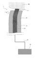
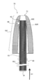
- FIG. 1 is a cross-sectional view conceptually showing the structure of a bioelectrode according to an embodiment of the present invention.
- FIG. 2 is a cross-sectional view conceptually showing a use state of a bioelectrode according to an embodiment of the present invention.
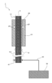
- a biological electrode 1 includes a conductive bundle 10 including a bundle 11 of a plurality of conductive wires 101, a conductive bundle located around the conductive bundle 10. 10, a holding body 20 that holds 10, a terminal 30 that is in electrical contact with the conductive bundle 10, and a wiring 40 that electrically connects the conductive bundle 10 and the terminal 30.
- the living body contact end portion 12 which is one end portion of the conductive bundle 10 protrudes from the holding body 20 and can contact the living body.
- the biological contact end 12 is made of a conductive material having at least a surface having biocompatibility. Examples of such materials include carbon-based materials; metal-based materials such as gold and titanium; and oxide-based materials such as indium tin oxide. If it is excellent in biocompatibility, the biological contact end 12 may be made of an organic material. From the viewpoint of availability and the like, at least the surface of the biological contact end 12 of the conductive bundle 10 is composed of one or more selected from the group consisting of a carbon-containing material, a gold-containing material, and a titanium-containing material. Is preferred.
- the conductive wire 101 is made of carbon fiber, including the portion located at the biocontact end 12.
- the thickness (short-axis diameter) of each conductive wire 101 a viewpoint which is easy to contact a biological body stably, a viewpoint which ensures handleability appropriately, a viewpoint which reduces the possibility of breaking, etc. Therefore, it may be preferable that the thickness (short axis diameter) of the conductive wire 101 is in the range of 10 ⁇ m to several hundred ⁇ m. There may be a plurality of types of diameters of the conductive wires 101 constituting the bundle 11.
- the diameter is in the range of about 10 ⁇ m to 50 ⁇ m.
- the holding body 20 has an elastic portion 21C, and in the bioelectrode 1 shown in FIG. 1, a portion of the holding body 20 located near the living body contact end portion 12 is an elastic portion 21C.
- the material constituting the holding body 20 is not limited as long as the elastic part 21C can have appropriate elasticity.
- Specific examples of the elastic material include silicone rubber; elastomer such as EPDM; natural rubber such as isoprene.
- the holding body 20 may be configured by a combination of such an elastic material and a hard material.
- the elastic part 21 ⁇ / b> C of the holding body 20 is in a state of being elastically deformed by contact with the conductive bundle 10. For this reason, the elastic recovery force EF acts on the conductive bundle 10 from the elastic portion 21 ⁇ / b> C, and the conductive bundle 10 has the contact holding portion 13 that is fitted to the holding body 20 by the elastic recovery force EF.
- the living body electrode 1 can be elastically deformed together with the holding body 20 in accordance with an external force applied to the living body contact end portion 12 in use.
- an external force F is applied to the living body BB due to the contact with the living body contact end 12
- the living body contact end 12 in the conductive bundle 10 is applied according to the external force.
- the shape of the holding body 20 is arbitrary.
- the holding body 20 includes a portion having a cylindrical shape having a major axis in a direction along the major axis direction of the conductive bundle 10.
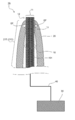
- FIG. 3 is a cross-sectional view conceptually showing the structure of a bioelectrode according to another embodiment of the present invention.
- the biological electrode 1A shown in FIG. 3 is different from the biological electrode 1 shown in FIG.
- the holding body 20 of the biological electrode 1A includes a portion 21T having a tapered shape whose outer shape becomes thinner toward a portion proximal to the biological contact end portion 12 of the conductive bundle 10.
- the elastic portion 21C is configured by the entire portion 21T having the tapered shape.
- the holding body 20 has such a shape, when the hair grows on the living body BB that is a contact target, it may be easy to avoid the hair. In some cases, the holder 20 can be manufactured more easily if it has such a shape.
- the entire elastic portion 21C of the holding body 20 is in contact with the conductive bundle 10, and the conductive bundle 10 is fitted.
- the biological electrode 1A shown in FIG. Only a portion proximal to the living body contact end 12 side of 20 is in contact with the conductive bundle 10, and the conductive bundle 10 is fitted by the elastic recovery force EF.
- the contact holding portion 13 is only a portion proximal to the biological contact end portion 12 side.
- FIG. 4 is a cross-sectional view conceptually showing the structure of a bioelectrode according to another embodiment of the present invention.
- a bioelectrode 1B shown in FIG. 4 includes a plurality of structures 50 each having a conductive bundle 10 and a holding body 20, and the plurality of structures 50 are electrically connected to one terminal 30.
- the wiring 40 is a branch wiring.
- a plurality of structures 50 are electrically connected to one terminal 30, in other words, a plurality of structures 50 are electrically connected to one terminal 30 included in biological electrode 1.
- the collection of electrical signals from the living body BB by the terminal 30 of the living body electrode 1 may be more stably realized.
- the conductive bundle 10 may be able to maintain a state where a plurality of conductive wires 101 are bundled, or a state where a plurality of conductive wires 101 are bundled is released. May be. If the plurality of conductive wires 101 included in the conductive bundle 10 are bundled in advance by some method, the state where the plurality of conductive wires 101 are bundled can be maintained even when the holding by the holding body 20 is released.
- the conductive bundle 10 includes a portion in which a plurality of conductive wires 101 are bundled by an adhesive material AD. It is done.
- the adhesive material AD include an acrylic adhesive material, a thermoplastic resin such as polypropylene, and a silicone elastic material.
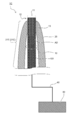
- the conductive bundle 10 is like a biological electrode 1D shown in FIG. It is mentioned that at least a part of the outer surface is made of a covering material CM for bundling a plurality of conductive wires 101.
- the material constituting the covering material CM is not limited. A resin material is mentioned as a specific example. From the viewpoint of increasing the degree of freedom of the material constituting the covering material CM, it is preferable that the outer surface of the biological contact end portion 12 of the conductive bundle 10 does not have a portion made of the covering material CM. In this case, the covering material CM can be made of an insulating material.
- the outer surface of the contact holding portion 13 of the conductive bundle 10 may have a portion made of the coating material CM or may not have such a portion.
- the outer surface of the contact holding portion 13 of the conductive bundle 10 does not have a portion made of the covering material CM, and the holder 20 directly holds the bundle 11 of the conductive wires 101 in the conductive bundle. In some cases, the relative position change of the body 10 with respect to the holding body 20 is less likely to occur.
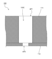
- FIG. 7 is a cross-sectional view conceptually showing the structure of a mold for manufacturing a bioelectrode according to an embodiment of the present invention.
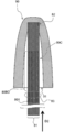
- 8 to 10 are cross-sectional views conceptually showing a process of manufacturing a bioelectrode according to an embodiment of the present invention using the mold shown in FIG.
- FIG. 11 is a cross-sectional view conceptually showing the structure of the bioelectrode manufactured by the manufacturing method shown in FIGS.
- the manufacturing method of the bioelectrode described with reference to FIGS. 7 to 11 includes a molding process described below.
- a mold 100 for manufacturing a biological electrode includes a first mold member 111 and a second mold member 112.
- the first mold member 111 has a through hole having an opening AP1
- the second mold member 112 has a through hole having an opening AP2.
- the first mold member 111 and the second mold member 112 are arranged so that the central axes of the respective through holes are aligned, and are fixed to each other to constitute the mold 100. Therefore, the mold 100 includes a hollow portion 100C including the opening AP1 and the opening AP2, and the hollow portion 100C has a central axis that passes through the centers of the opening AP1 and the opening AP2.
- the opening diameter of the opening AP1 is substantially close to the outer diameter of the holder 20 of the biological electrode 1
- the opening diameter of the opening AP2 is substantially close to the outer diameter of the conductive bundle 10.
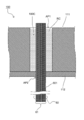
- a bundle-like conductive member 60 that has a portion where a plurality of conductive wires 601 are bundled as shown in FIG.
- the bundle 61 of the plurality of conductive wires 601 may be preliminarily bundled with an adhesive material, or a covering material for preliminarily bundling the bundle 61 may be provided.
- a bundle-like conductive member 60 shown in FIG. 8 a bundle 61 is preliminarily bundled with an adhesive material at a portion not shown.
- the bundle-shaped conductive member 60 is inserted into the hollow portion 100C so that the central axis of the hollow portion 100C of the mold 100 and the long axis of the bundle-shaped conductive member 60 are aligned.
- the bundled conductive members 60 are arranged so as to protrude from the openings AP1 and AP2.
- the diameter of the bundled conductive member 60 is substantially equal to the diameter of the opening AP2, and the bundled conductive member 60 is fitted in the through hole provided with the opening AP2 of the second mold member 112.
- elastic material for example, silicone resin
- the fluidity can be improved by heating the resin.
- the elastic material RC can have a crosslinked structure
- the fluidity of the elastic material RC can be increased by setting the degree of crosslinking by the crosslinking agent to a low level.
- the elastic material RC can also be impregnated into the bundle 61 of the plurality of conductive wires 601 in the bundle-like conductive member 60.
- the elastic material RC in a state of low fluidity is transferred from the opening AP2 to the outside of the mold 100. Leakage into the water is suppressed.
- the fluidity of the elastic material RC supplied into the hollow portion 100C is lowered, and the holding body 20 is formed from the elastic material RC in the hollow portion 100C.
- the holding body 20 formed of the elastic material RC is disposed around the bundled conductive member 60.
- the fluidity of the elastic material RC positioned between the plurality of conductive wires 601 constituting the bundle 61 of the bundle-like conductive member 60 is also reduced, and the plurality of conductive wires 601 are bundled by a member formed from the elastic material RC. .
- the conductive bundle 10 including the bundle 11 of the plurality of conductive lines 101 composed of the plurality of conductive lines 601 and the member that bundles the conductive lines 101 is formed, and the holding body 20 formed of the elastic material RC is disposed around the conductive bundle 10.
- a member (including the structure 50) constituting the biological electrode 1 is obtained.
- the method for increasing the fluidity of the elastic material RC in a low fluidity state is appropriately set according to the properties of the elastic material RC.
- the elastic material RC is a thermoplastic silicone resin
- the fluidity of the elastic material RC can be increased by lowering the temperature of the elastic material RC.
- the elastic material RC can have a crosslinked structure
- the fluidity of the elastic material RC can be improved by increasing the crosslinking density in the elastic material RC by heating or the like.
- Such a decrease in the fluidity of the elastic material RC is usually accompanied by volume contraction of the elastic material RC. Therefore, when the holding body 20 is formed from the elastic material RC, the holding body 20 is elastically deformed by itself and tightens the conductive bundle 10. Formed.
- the conductive bundle 10 includes a contact holding portion 13 that is fitted to the holding body 20 by the elastic recovery force of the holding body 20.
- the member including the conductive bundle 10 and the holding body 20 is taken out from the mold 100, the conductive bundle 10 and the clip 41 are electrically connected using the clip 41, and the clip 41 and the terminal 30 are connected by the wiring 40.
- the bioelectrode 1 is obtained by electrical connection.
- the holding body 20 and the terminal 30 may be attached.
- the elastic material RC is supplied to the periphery of the bundle-like conductive member 60
- the elastic material RC is supplied so that the elastic material RC is also in contact with the terminal 30, and the fluidity of the elastic material RC to be subsequently performed is supplied.
- the holding body 20 formed of the elastic material RC is attached to the terminal 30 due to the decrease in.
- FIG. 12 is a cross-sectional view conceptually showing the structure of an example of a hollow elastic member for manufacturing a bioelectrode according to another embodiment of the present invention.
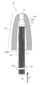
- FIG. 13 is a cross-sectional view conceptually showing a process of manufacturing a bioelectrode according to another embodiment of the present invention using the hollow elastic member shown in FIG.
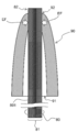
- FIG. 14 is a sectional view conceptually showing the structure of a bioelectrode manufactured using a hollow elastic member.
- the biological electrode manufacturing method described with reference to FIGS. 12 to 14 includes an insertion step described below.
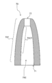
- the hollow elastic member 70 shown in FIG. 12 is made of an elastic body having a hollow portion 70 ⁇ / b> C including a first opening 71 and a second opening 72.
- the hollow elastic member 70 is a member that gives the holding body 20.
- the hollow elastic member 70 is made of the same kind of elastic material as the material constituting the elastic portion 21 ⁇ / b> C of the holding body 20.
- the opening diameter of the first opening 71 is larger than the opening diameter of the second opening 72
- the outer shape of the hollow elastic member 70 is a tapered shape that narrows from the first opening 71 side to the second opening 72 side. 70T.
- the inner surface of the hollow elastic member 70 that defines the hollow portion 70C of the hollow elastic member 70 also has a tapered shape 70CT that narrows from the first opening 71 side to the second opening 72 side.
- a bundled conductive member 80 that has a portion where a plurality of conductive wires 801 are bundled and gives the conductive bundle 10 is used.
- the bundled conductive member 80 has the same configuration as that of the bundled conductive member 60 used when the biological electrode 1 is manufactured. As shown in FIG. 8, the bundled conductive member 80 has a portion 80BD in which a bundle 81 of a plurality of conductive wires 801 is bundled with a substance AD having adhesiveness.
- the insertion end 82 which is one end of the bundle-like conductive member 80, is inserted into the hollow portion 70 ⁇ / b> C from the first opening 71 of the hollow elastic member 70. insert.
- the inner side surface of the hollow elastic member 70 defining the hollow portion 70 ⁇ / b> C has a tapered shape 70 ⁇ / b> CT whose diameter is narrowed toward the second opening 72, and therefore the insertion direction of the bundled conductive member 80.
- D1 approaches the direction along the line connecting the opening center of the first opening 71 and the opening center of the second opening 72 as the degree of insertion proceeds.
- the insertion end portion 82 of the bundled conductive member 80 protrudes from the second opening 72 and is hollow in the vicinity of the second opening 72.
- the elastic member 70 fits the bundled conductive member 80.
- the opening diameter of the second opening 72 is appropriately adjusted, specifically, if the opening diameter of the second opening 72 is set slightly narrower than the outer diameter of the bundled conductive member 80, the second In the vicinity of the opening 72, the hollow elastic member 70 can be caused to undergo only elastic deformation.
- the insertion opening 82 of the bundle-like conductive member 80 is protruded from the second opening 72, so that the second opening Breakage of the hollow elastic member 70 in the vicinity of the portion 72 and cleavage of the second opening 72 occur.
- the bundled conductive member 80 may be appropriately fitted by the hollow elastic member 70 in some cases.
- the hollow elastic member 70 has two openings (the first opening 71 and the second opening 72), but is not limited thereto.
- FIG. 15 conceptually shows a process of manufacturing a bioelectrode according to another embodiment of the present invention using another example of a hollow elastic member for manufacturing a bioelectrode according to another embodiment of the present invention.
- FIG. 16 and 17 are sectional views conceptually showing a process of manufacturing a bioelectrode according to another embodiment of the present invention using the hollow elastic member shown in FIG.
- the hollow elastic member 90 shown in FIG. 15 has only the first opening 91.
- the hollow elastic member 90 shown in FIG. the bundled conductive member 80 is inserted from the first opening 91 into the hollow portion 90C. Then, the insertion end portion 82 of the bundle-like conductive member 80 is brought into contact with the inner side surface defining the hollow elastic member 90. Further, by inserting the bundled conductive member 80 along the direction D2, the bundled conductive member 80 is transferred from the inner surface defining the hollow elastic member 90 into the elastic body constituting the hollow elastic member 90 as shown in FIG. The insertion end 82 of the member 80 is pierced. Finally, as shown in FIG.
- the bundle-shaped conductive member 80 is passed through the hollow elastic member 90, and the second opening 92, which is an opening other than the first opening 91, is formed.
- the insertion end portion 82 is protruded from the two openings 92. Also by doing in this way, the biological electrode 1C as shown in FIG. 14 can be manufactured.
- the bundle-like conductive member 80 inserted into the hollow portions 70 ⁇ / b> C and 90 ⁇ / b> C of the hollow elastic members 70 and 90 has no external force by using an adhesive material AD in advance.
- the plurality of conductive lines 801 can maintain a bundled form.
- the bundled conductive member 80 is not limited to this.
- the bundled conductive member 80 may not be able to maintain the bundled shape of the plurality of conductive wires 801 without external force. Even in such a case, the bundle-shaped conductive member 80 is placed in the hollow portions 70C and 90C of the hollow elastic members 70 and 90 by using an appropriate guide (one having a cylindrical shape is exemplified). Insert it.
- the bundled conductive member 80 can maintain the plurality of conductive wires 801 in a bundled form without any external force can be achieved by using a material AD having adhesiveness.
- the bundled conductive member may have a covering material that preliminarily bundles a plurality of conductive wires.
- FIG. 18 shows a bioelectrode according to still another embodiment of the present invention using an example of a hollow elastic member and an example of a bundled conductive member for manufacturing a bioelectrode according to still another embodiment of the present invention. It is sectional drawing which shows notionally the process of manufacturing.
- FIG. 19 shows a bioelectrode according to still another embodiment of the present invention using an example of a hollow elastic member and an example of a bundle-like conductive member for manufacturing a bioelectrode according to still another embodiment of the present invention. It is sectional drawing which shows notionally the process of manufacturing.
- FIG. 19 shows a bioelectrode according to still another embodiment of the present invention using an example of a hollow elastic member and an example of a bundle-like conductive member for manufacturing a bioelectrode according to still another embodiment of the present invention. It is sectional drawing which shows notionally the process of manufacturing.
- FIG. 19 shows a bioelectrode according to still another embodiment of the present invention using an example of a hollow
- FIG. 20 shows a bioelectrode according to still another embodiment of the present invention using an example of a hollow elastic member and an example of a bundled conductive member for manufacturing a bioelectrode according to still another embodiment of the present invention. It is sectional drawing which shows notionally the process of manufacturing.
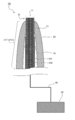
- FIG. 21 is a cross-sectional view conceptually showing the structure of a bioelectrode manufactured by the manufacturing method shown in FIGS.
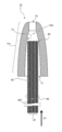
- a covering material 83 is disposed so as to cover the side surface of the bundle 81 of the plurality of conductive wires 801, and the plurality of conductive wires 801 have a bundle-like form. Sustainable. As shown in FIG. 18, when the insertion of the bundled conductive member 80 from the first opening 71 into the hollow portion 70C (along the direction D1) proceeds, the inner side surface 73 of the hollow elastic member 70 is inserted. Contact with the end 82 occurs.
- the inner side surface 73 of the hollow elastic member 70 is elastically deformed, and the side surface of the bundle-like conductive member 80 including the insertion end portion 82 is the side of the hollow elastic member 70. Slides with the inner surface 73. At this time, the inner side surface 73 of the hollow elastic member 70 presses the side surface of the bundle-like conductive member 80 by the elastic recovery force EF (FIG. 19) of the hollow elastic member 70.
- the covering material 83 of the bundled conductive member 80 is peeled off, and an exposed region 80 ⁇ / b> E in which the side surface of the bundle 81 of the plurality of conductive wires 801 is exposed is generated.
- the covering material 83 is in a partially peeled state.
- the covering material 83 only needs to be made of a material that can be easily peeled by sliding between the hollow elastic member 70 and the bundle-like conductive member 80.
- the bundle-shaped conductive member 80 in the direction D1 is advanced, as shown in FIG. 20, along with the elastic deformation of the hollow elastic member 70 whose diameter of the second opening 72 is increased, the bundle-shaped conductive member The insertion end 82 of 80 protrudes from the hollow elastic member 70. At that time, both the protruding portion of the bundle-like conductive member 80 and the portion fitted by the hollow elastic member 70 have the exposed region 80E on the side surface.
- the conductive bundle 10 can be obtained from the bundle-shaped conductive member 80, and the holding body 20 can be obtained from the hollow elastic member 70. Then, by electrically connecting the conductive bundle 10 and the terminal 30 using the wiring 40 and the clip 41, the biological electrode 1D is obtained as shown in FIG.
- FIG. 22 is a cross-sectional view conceptually showing the structure of another example of a bundled conductive member for manufacturing a biological electrode according to another embodiment of the present invention.
- FIG. 23 is a front view (a) and a cross-sectional view (b) conceptually showing the structure of another example of a bundle-like conductive member for manufacturing a bioelectrode according to another embodiment of the present invention.
- FIG. 24 is a front view (a) and a cross-sectional view (b) conceptually showing the structure of still another example of a bundle-like conductive member for producing a bioelectrode according to another embodiment of the present invention. is there.
- a bundle-shaped conductive member 80A shown in FIG. 22 includes a covering material 84 having a region with a non-uniform thickness.
- the covering material 84 is formed so as to cover the entire side surface of the bundle 81 of the plurality of conductive wires 801 similarly to the covering material 83 included in the bundle-like conductive member 80 shown in FIGS.
- Thick thick portions 84B and thin thin portions 84D are alternately arranged along the long axis direction of the bundle-like conductive member 80A.
- the covering material 85 included in the bundle-like conductive member 80B shown in FIG. 23 has a region where the thickness is not uniform, and in that region, the material constituting the covering material 85 is the side surface of the bundle 81 of the plurality of conductive wires 801. A portion that is not provided above, that is, a portion 81E where the side surface of the bundle 81 is exposed is provided.
- the members constituting the covering material 85 are arranged in an island shape on the side surface of the bundle 81, before the insertion end portion 82 of the bundle-like conductive member 80B protrudes from the hollow elastic body 70. When coming into contact with the hollow elastic body 70, the covering material 85 is easily peeled from the side surface of the bundle 81 of the plurality of conductive wires 801.
- the covering material 86 provided in the bundle-like conductive member 80C shown in FIG. 24 has a slit processing portion 86S that is cut in the thickness direction.
- the insertion end portion 82 of the bundle-like conductive member 80C is provided.
- a living body electrode according to some embodiments of the present invention is pressed against the living body surface, the living body contact end portion of the living body electrode is brought into contact with the skin of the living body, and an electrical signal is collected from the living body contact end portion.
- An electrical signal can be collected from.
- living bodies include mammals and birds having hair and wings. Specific examples of mammals include pets such as dogs and cats, domestic animals such as cattle, wild species such as monkeys, and humans. Specific examples of birds include wild species such as chickens and pigeons, wild animals such as ibis and grouse. Species are mentioned.
- the type of measurement signal is not limited. It may be an electroencephalogram as described above, or an electrical signal related to the operation of the heart (a signal for obtaining an electrocardiogram is given as a specific example).
- FIG. 25 is a conceptual diagram showing an example of a usage state of a bioelectrode according to some embodiments of the present invention.
- the measurement target is a human BBH
- the headgear HG is attached to the head of the human BBH.
- a plurality of biological electrodes 1 are attached to the net cap 2, and the state where the biological contact end 12 of the biological electrode 1 is in contact with the scalp is maintained by the net cap 2.
- the lead wires 3 electrically connected to the terminals 30 of the respective bioelectrodes 1 are collected at the terminals 4 and connected to a measuring device (not shown).
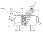
- FIG. 26 is a conceptual diagram showing another example of the usage state of the bioelectrode according to some embodiments of the present invention.
- the measurement object is an animal other than a human (specifically, a cow) BBA
- a fixed gear BG is attached to the trunk of the animal BBA.
- a plurality of biological electrodes 1 are attached to the net 5, and the state where the biological contact end portion 12 of the biological electrode 1 is in contact with the skin of the animal BBA is maintained by the net 5.
- the lead wires 3 electrically connected to the terminals 30 of the respective bioelectrodes 1 are collected at the terminals 4 and connected to a measuring device (not shown).
- the conductive bundle 10 and the terminal 30 are electrically connected via the clip 41 and the wiring 40, but the conductive bundle 10 and the terminal 30 are made of conductive paste. May be electrically connected to each other, or electrical connection may be made directly.
- the covering material removal for removing the covering material 83 at the insertion end portion 82 protruding from the second opening 72 after the insertion attaching process You may further provide a process.
- FIG. 27 is a perspective view conceptually showing the appearance of the bioelectrode according to the embodiment of the present invention.
- the biological electrode 1 ⁇ / b> E according to the example has eight structures 50 including the conductive bundle 10 and the holding body 20.
- the resin part RP is located on the side opposite to the side where the living body contact end 12 is located, and the terminal 30 is located on the opposite side of the surface of the resin part RP where the structure 50 is provided. Is provided.
- a wiring 40 that electrically connects the conductive bundle 10 of each structure 50 and the terminal 30 is embedded in the resin portion RP.
- the conductive wire 101 of the conductive bundle 10 was made of carbon fiber having a diameter of about 10 ⁇ m, and the bundle 11 of the plurality of conductive wires 101 had a diameter of about 1 mm.
- FIG. 28 is a perspective view conceptually showing the appearance of a bioelectrode according to a related art as a comparative example.
- the bioelectrode 200 according to the comparative example has nine metal pins 201 corresponding to the structure 50 of the bioelectrode 1E, and each tip is made of metal corresponding to the biocontact end 12 of the bioelectrode 1E.
- the spherical body 202 is provided.
- the base 203 corresponding to the resin part RP of the bioelectrode 1E is also made of metal, and the end 204 opposite to the side where the pin 201 is provided corresponds to the terminal 30 of the bioelectrode 1E.
- the bioelectrode 1E according to the example and the bioelectrode 200 according to the comparative example were each connected to an impedance meter (“MaP811” manufactured by Nihon Santech Co., Ltd.), and impedance measurement was performed at a measurement frequency of 30 Hz.
- the reference electrode for measurement was a gel electrode for electrocardiography (“Ellrode” manufactured by Mets), and a conductive paste (“E.Gel” manufactured by GE Health Japan) was used.
Landscapes
- Life Sciences & Earth Sciences (AREA)
- Health & Medical Sciences (AREA)
- Medical Informatics (AREA)
- Biophysics (AREA)
- Pathology (AREA)
- Engineering & Computer Science (AREA)
- Biomedical Technology (AREA)
- Heart & Thoracic Surgery (AREA)
- Physics & Mathematics (AREA)
- Molecular Biology (AREA)
- Surgery (AREA)
- Animal Behavior & Ethology (AREA)
- General Health & Medical Sciences (AREA)
- Public Health (AREA)
- Veterinary Medicine (AREA)
- Measurement And Recording Of Electrical Phenomena And Electrical Characteristics Of The Living Body (AREA)
Abstract
La présente invention décrit une bioélectrode (1) qui est appliquée à une peau pileuse et qui est capable d'utilisation répétée, et qui est capable d'entrer de manière appropriée en contact avec la peau tout en réduisant la charge sur la peau, ladite bioélectrode (1) étant prévue avec : un faisceau électroconducteur (10) comprenant un faisceau (11) d'une pluralité de câbles électroconducteurs (101); un dispositif de maintien (20) positionné autour du faisceau électroconducteur (10) afin de maintenir le faisceau électroconducteur (10); et une borne (30) en contact électrique avec le faisceau électroconducteur (10). Une extrémité de contact avec le corps (12), qui est une extrémité du faisceau électroconducteur (10), comprend un matériau électroconducteur dont au moins la surface est biocompatible. L'extrémité de contact avec le corps (12) qui se projette depuis l'élément de maintien (20) afin d'être capable d'entrer en contact avec un corps. Le dispositif de maintien (20) présente une partie élastique (21C). Au moins une partie du faisceau électroconducteur (10) est capable de se déformer de manière élastique parallèlement au dispositif de maintien (20) en réponse à la force (F) externe appliquée à l'extrémité de contact avec le corps (12).
Priority Applications (1)
| Application Number | Priority Date | Filing Date | Title |
|---|---|---|---|
| JP2018504618A JP6486551B2 (ja) | 2016-03-11 | 2017-03-10 | 生体電極、生体電極の製造方法、生体から電気信号を収集する方法 |
Applications Claiming Priority (2)
| Application Number | Priority Date | Filing Date | Title |
|---|---|---|---|
| JP2016-049001 | 2016-03-11 | ||
| JP2016049001 | 2016-03-11 |
Publications (1)
| Publication Number | Publication Date |
|---|---|
| WO2017155109A1 true WO2017155109A1 (fr) | 2017-09-14 |
Family
ID=59790441
Family Applications (1)
| Application Number | Title | Priority Date | Filing Date |
|---|---|---|---|
| PCT/JP2017/009790 Ceased WO2017155109A1 (fr) | 2016-03-11 | 2017-03-10 | Bioélectrode, procédé de fabrication d'une bioélectrode, et procédé de collecte de signaux électriques provenant de corps |
Country Status (2)
| Country | Link |
|---|---|
| JP (1) | JP6486551B2 (fr) |
| WO (1) | WO2017155109A1 (fr) |
Cited By (3)
| Publication number | Priority date | Publication date | Assignee | Title |
|---|---|---|---|---|
| JP2018134247A (ja) * | 2017-02-22 | 2018-08-30 | アルプス電気株式会社 | 生体情報測定用電極 |
| WO2018186212A1 (fr) * | 2017-04-07 | 2018-10-11 | アルプス電気株式会社 | Électrode de mesure d'informations biologiques et procédé de mesure d'informations biologiques |
| JP2021145689A (ja) * | 2020-03-16 | 2021-09-27 | 住友ベークライト株式会社 | 脳波測定用電極および脳波測定装置 |
Citations (6)
| Publication number | Priority date | Publication date | Assignee | Title |
|---|---|---|---|---|
| JPS4853891U (fr) * | 1971-10-18 | 1973-07-11 | ||
| JPS62231621A (ja) * | 1986-01-27 | 1987-10-12 | ウエスチングハウス エレクトリック コ−ポレ−ション | 脳波測定用ヘツドセツト |
| JPH0482533A (ja) * | 1990-07-24 | 1992-03-16 | Yukio Sekine | 動物用生体電極装置 |
| JP2012019962A (ja) * | 2010-07-15 | 2012-02-02 | Nippon Telegr & Teleph Corp <Ntt> | 剣山型乾電極及びその作製方法 |
| JP2013111361A (ja) * | 2011-11-30 | 2013-06-10 | Japan Health Science Foundation | 脳波測定用電極、脳波測定用部材、及び、脳波測定装置 |
| JP2013240485A (ja) * | 2012-05-21 | 2013-12-05 | National Institute Of Information & Communication Technology | 脳波計測用電極、脳波計測用電極を備える脳波計測用電極付キャップ |
-
2017
- 2017-03-10 WO PCT/JP2017/009790 patent/WO2017155109A1/fr not_active Ceased
- 2017-03-10 JP JP2018504618A patent/JP6486551B2/ja not_active Expired - Fee Related
Patent Citations (6)
| Publication number | Priority date | Publication date | Assignee | Title |
|---|---|---|---|---|
| JPS4853891U (fr) * | 1971-10-18 | 1973-07-11 | ||
| JPS62231621A (ja) * | 1986-01-27 | 1987-10-12 | ウエスチングハウス エレクトリック コ−ポレ−ション | 脳波測定用ヘツドセツト |
| JPH0482533A (ja) * | 1990-07-24 | 1992-03-16 | Yukio Sekine | 動物用生体電極装置 |
| JP2012019962A (ja) * | 2010-07-15 | 2012-02-02 | Nippon Telegr & Teleph Corp <Ntt> | 剣山型乾電極及びその作製方法 |
| JP2013111361A (ja) * | 2011-11-30 | 2013-06-10 | Japan Health Science Foundation | 脳波測定用電極、脳波測定用部材、及び、脳波測定装置 |
| JP2013240485A (ja) * | 2012-05-21 | 2013-12-05 | National Institute Of Information & Communication Technology | 脳波計測用電極、脳波計測用電極を備える脳波計測用電極付キャップ |
Cited By (5)
| Publication number | Priority date | Publication date | Assignee | Title |
|---|---|---|---|---|
| JP2018134247A (ja) * | 2017-02-22 | 2018-08-30 | アルプス電気株式会社 | 生体情報測定用電極 |
| WO2018186212A1 (fr) * | 2017-04-07 | 2018-10-11 | アルプス電気株式会社 | Électrode de mesure d'informations biologiques et procédé de mesure d'informations biologiques |
| JPWO2018186212A1 (ja) * | 2017-04-07 | 2019-12-19 | アルプスアルパイン株式会社 | 生体情報測定用電極および生体情報の測定方法 |
| JP2021145689A (ja) * | 2020-03-16 | 2021-09-27 | 住友ベークライト株式会社 | 脳波測定用電極および脳波測定装置 |
| JP7505215B2 (ja) | 2020-03-16 | 2024-06-25 | 住友ベークライト株式会社 | 脳波測定用電極および脳波測定装置 |
Also Published As
| Publication number | Publication date |
|---|---|
| JP6486551B2 (ja) | 2019-03-20 |
| JPWO2017155109A1 (ja) | 2018-07-26 |
Similar Documents
| Publication | Publication Date | Title |
|---|---|---|
| JP5842198B2 (ja) | 脳波測定用電極、脳波測定用部材、及び、脳波測定装置 | |
| JP5476570B2 (ja) | 剣山型乾電極及びその作製方法 | |
| EP3585255B1 (fr) | Appareil et procédé de réalisation d'électro-encéphalographie | |
| EP3033994B1 (fr) | Électrode pour détection biopotentielle | |
| JP6486551B2 (ja) | 生体電極、生体電極の製造方法、生体から電気信号を収集する方法 | |
| US12042649B2 (en) | Cortical stimulation and recording electrode and method for making such electrode | |
| CN106108895B (zh) | 颅内电极 | |
| KR101785287B1 (ko) | 마이크로니들 전극 패치 및 이의 제조 방법 | |
| US8682409B1 (en) | MR conditional needle and surface electrodes | |
| WO2018230445A1 (fr) | Électrode biologique | |
| US20150238100A1 (en) | Sensor electrode device | |
| WO2016075298A2 (fr) | Réseau d'électrodes implantable | |
| CN113261969B (zh) | 脑电极针体、脑电极单元及阵列化脑电极 | |
| CN111053554A (zh) | 一种超微柔性线性深部脑电极 | |
| US9504424B2 (en) | Skin screw electrodes | |
| CN103230271B (zh) | 一种可用于获取四肢表面肌电信号的可佩戴电极阵列 | |
| US20250185971A1 (en) | Braided multi-electrode emg needles for advanced electrodiagnostics | |
| CN207856071U (zh) | 一种神经刺激电极 | |
| US10004419B2 (en) | Electrode for measuring living body signal | |
| KR101674886B1 (ko) | 통풍이 뛰어난 건식 전극 센서 | |
| CN111529924A (zh) | 一种深部脑刺激电极装置 | |
| US11672483B2 (en) | Skin screw electrodes | |
| WO2022176559A1 (fr) | Bioélectrode | |
| US11117182B2 (en) | Methods for fabrication of an electrode delivery system | |
| JP2019088417A (ja) | 生体情報測定用電極及び生体情報測定用電極の製造方法 |
Legal Events
| Date | Code | Title | Description |
|---|---|---|---|
| ENP | Entry into the national phase |
Ref document number: 2018504618 Country of ref document: JP Kind code of ref document: A |
|
| NENP | Non-entry into the national phase |
Ref country code: DE |
|
| 121 | Ep: the epo has been informed by wipo that ep was designated in this application |
Ref document number: 17763441 Country of ref document: EP Kind code of ref document: A1 |
|
| 122 | Ep: pct application non-entry in european phase |
Ref document number: 17763441 Country of ref document: EP Kind code of ref document: A1 |