WO2017155143A1 - Appareil de fabrication de traverses pour pare-chocs de véhicule - Google Patents
Appareil de fabrication de traverses pour pare-chocs de véhicule Download PDFInfo
- Publication number
- WO2017155143A1 WO2017155143A1 PCT/KR2016/002451 KR2016002451W WO2017155143A1 WO 2017155143 A1 WO2017155143 A1 WO 2017155143A1 KR 2016002451 W KR2016002451 W KR 2016002451W WO 2017155143 A1 WO2017155143 A1 WO 2017155143A1
- Authority
- WO
- WIPO (PCT)
- Prior art keywords
- sides
- clamp
- cylinder
- tension
- vehicle bumper
- Prior art date
- Legal status (The legal status is an assumption and is not a legal conclusion. Google has not performed a legal analysis and makes no representation as to the accuracy of the status listed.)
- Ceased
Links
Images




Classifications
-
- B—PERFORMING OPERATIONS; TRANSPORTING
- B21—MECHANICAL METAL-WORKING WITHOUT ESSENTIALLY REMOVING MATERIAL; PUNCHING METAL
- B21D—WORKING OR PROCESSING OF SHEET METAL OR METAL TUBES, RODS OR PROFILES WITHOUT ESSENTIALLY REMOVING MATERIAL; PUNCHING METAL
- B21D7/00—Bending rods, profiles, or tubes
- B21D7/02—Bending rods, profiles, or tubes over a stationary forming member; by use of a swinging forming member or abutment
- B21D7/024—Bending rods, profiles, or tubes over a stationary forming member; by use of a swinging forming member or abutment by a swinging forming member
- B21D7/028—Bending rods, profiles, or tubes over a stationary forming member; by use of a swinging forming member or abutment by a swinging forming member and altering the profile at the same time, e.g. forming bumpers
-
- B—PERFORMING OPERATIONS; TRANSPORTING
- B21—MECHANICAL METAL-WORKING WITHOUT ESSENTIALLY REMOVING MATERIAL; PUNCHING METAL
- B21D—WORKING OR PROCESSING OF SHEET METAL OR METAL TUBES, RODS OR PROFILES WITHOUT ESSENTIALLY REMOVING MATERIAL; PUNCHING METAL
- B21D11/00—Bending not restricted to forms of material mentioned in only one of groups B21D5/00, B21D7/00, B21D9/00; Bending not provided for in groups B21D5/00 - B21D9/00; Twisting
- B21D11/20—Bending sheet metal, not otherwise provided for
-
- B—PERFORMING OPERATIONS; TRANSPORTING
- B21—MECHANICAL METAL-WORKING WITHOUT ESSENTIALLY REMOVING MATERIAL; PUNCHING METAL
- B21D—WORKING OR PROCESSING OF SHEET METAL OR METAL TUBES, RODS OR PROFILES WITHOUT ESSENTIALLY REMOVING MATERIAL; PUNCHING METAL
- B21D53/00—Making other particular articles
- B21D53/88—Making other particular articles other parts for vehicles, e.g. cowlings, mudguards
Definitions
- the present invention relates to an apparatus for manufacturing a vehicle bumper beam that is formed to have a curvature on both sides of the vehicle bumper beam, and more particularly, by pulling the material of the beam from both sides while lowering vertically to give curvature to both sides of the beam.
- the present invention relates to a device for manufacturing a beam for a vehicle bumper.
- the front and rear of the vehicle is equipped with a bumper to absorb the impact in the event of a collision, which is an important part requiring a relatively complex structure and analysis that must meet both stability and design at the same time.
- the vehicle bumper beam is manufactured by applying a method such as stretch bending, roll bending, etc. in order to mold the extruded cross section to a predetermined curvature.
- Stretch bending is a technology of fixing both ends of a permanently deformed metal pipe and bending by changing the angles of both ends of the metal pipe with hydraulic pressure. Roll bending is placed along a certain curvature to allow the metal pipe material to rotate. It is a technology to inject and bend.
- the stretch bending has a disadvantage in that the productivity is low because the process is introduced to the material, the process is taken out to the product, roll bending is not stretched to the permanent deformation point of the plastic deformation of the material due to the spring back There is a disadvantage that the quality of curvature cannot be guaranteed.
- Patent No. 10-1340383 combines the advantages of stretch bending and roll bending to achieve curvature due to various designs through rollers moving in multiple axes. It has been proposed to meet the specifications required for the bumper with precision to minimize cracks and wrinkles to ensure excellent quality and stability, the present invention also proposes an improvement to the applicant's registered patent.
- Patent Document 1 Republic of Korea Patent No. 10-1340383 (2013.12.11)
- an object of the present invention is to bend the bending portion of the beam in the state in which the tension portion is tensioning the both sides of the beam desired curvature at both ends of the beam To provide an apparatus for manufacturing a vehicle bumper beam for precise processing.
- the present invention also provides an apparatus for manufacturing a beam for a vehicle bumper that can improve the convenience of use and the fixing force of the beam by clamping the beam by only the operation of the clamp cylinder and the core body cylinder without a separate fixing means. There is another purpose.
- the present invention provides a device for manufacturing a vehicle bumper beam having a curvature formed on both sides of the vehicle bumper beam, the support is provided on the ground and is mounted on the ground and the suspension of the beam is seated A main body installed; It is provided in the upper center of the main body, the press to fix the suspension of the beam seated on the support.
- a pressurizing part comprising a pressurizing cylinder configured to move downward and a pressurizing body coupled to the rod of the pressurizing cylinder to move up and down;
- Tension cylinders which operate on both sides of the main body, an actuated bundle formed with a clamp groove to be provided on the tension cylinder rod and a clamp means for clamping both ends of the beam to the inner side, and a rod for receiving the rod of the tension cylinder
- a tension unit configured to rotate on both sides of the copper plate and the rotating plate, the tension unit for tensioning both sides of the beam by operating the tension cylinder while clamping both ends of the beam by the clamping means; Win on both sides of the upper part of the main body.
- It consists of a bending cylinder in which the lowering movement is made, an actuator coupled to the rod of the bending cylinder to move up and down, and a receptor for rotatably receiving the rotation axis of the tension portion at both ends of the actuator, thereby tensioning both sides of the beam. It provides a device for manufacturing a vehicle bumper comprising a; bending portion for moving the tension portion to the lower side to be rotated in the receptor to form a curvature is formed on both sides of the beam.
- the clamp means includes a clamp body for clamping the upper and both sides of the beam by being moved forward and backward by the clamp cylinder in the clamp groove, and the clamp body slides on the upper and both sides of the beam due to the operation of the clamp cylinder. It is characterized in that the clamp cylinder and the clamp body are installed to taper.
- the clamp means includes a core body that is introduced into the interior of the beam by the operation of the core cylinder in the clamp groove, the core body is configured to deform like when the beam is bent by the bending portion to prevent the damage of the beam It is characterized by.
- the bending portion performs bending of the beam while the tension portion tensions both sides of the beam, precise processing is performed at both ends of the beam with a desired curvature, and the beam is made regardless of the strength of the beam. This enables the production of high-quality beams of high strength, thereby increasing the added value.
- the clamp cylinder and the clamp body of the clamp means are installed to taper, and the clamp body clamps the upper and both sides of the beam only by the operation of the clamp cylinder without a separate fixing means due to the plurality of protrusions formed on the clamp body, thereby improving convenience in use and improving the beam. There is an effect that can increase the fixing power.
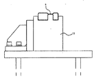
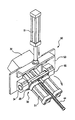
- Figure 2 is a side view showing the form in which the beam is seated on the support according to the invention
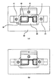
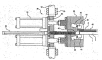
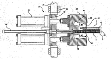
- 3 to 7 is an exemplary view showing a preferred form in which the beam is clamped by the clamping means
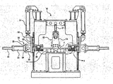
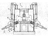
- 10 to 13 is an exemplary view showing a preferred form in which the beam is bent by the bending means according to the present invention
- FIG. 14 is an exemplary view showing a preferred form in which the core body according to the present invention is drawn and bent into the beam.
- clamp body 42 clamp cylinder
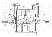
- FIGS. 1 and 2 are exemplary views showing a preferred embodiment of the present invention, as shown in FIGS. 1 and 2, the present invention relates to an apparatus for manufacturing a vehicle bumper beam having a curvature formed on both sides of the vehicle bumper beam (1).
- the main body 10 is installed on the ground, the pressing unit 20 for pressing the interruption of the beam 1 from the main body 10, the tension unit 30 is provided with a clamp means to tension both sides of the beam (1) It is composed of a bending part 50 for bending both sides of the beam 1 by rotating the tension part 30 by lowering the tension part 30.
- the conventional shape of the beam 1 here has a through portion to absorb shocks from external forces on both sides and a recess is formed to have rigidity between the through portions.
- the main body 10 is composed of a box-shaped frame which is installed on the ground, and is provided with a support 11 for supporting the beam 1 to which the interruption of the beam 1 is seated.
- the beam 1 is configured to be fixed.
- the pressing unit 20 is provided at the upper center of the main body 10, and lifts and fixes the interruption of the beam 1 seated on the support 11.
- both sides of the beam 1 are molded by the tensioning portion 30 and the bending portion 50 which are coupled to the rod of the pressure cylinder 21 and the rod of the pressure cylinder 21 to move downward, and are described later, It is configured to fix the center of the beam (1).
- the tension unit 30 is mounted on the tension cylinder 31 operated on both sides of the main body 10 and the tension cylinder 31 rod, and clamp means for clamping both ends of the beam 1 to the inner side. It is configured to include a working bundle 32 in which the groove 33 is formed.
- the tension unit 30 is configured to include a rotating plate 35 for receiving the rod of the tension cylinder 31 and a rotating shaft 34 provided on both sides of the rotating plate 35.
- the tension unit 30 is configured to tension both sides of the beam 1 by operating the tension cylinder 31 while clamping both ends of the beam 1 by the clamp means provided in the clamp groove 33. Will be.
- the bending part 50 wins at both upper sides of the main body 10.
- a bending cylinder 51 in which a lowering movement is performed, an actuator 53 coupled to a rod of the bending cylinder 51 to move up and down, and a rotation shaft 34 of the tension part 30 at both ends of the actuator. It consists of a receptor 55 that rotatably receives it.
- the bending part 50 moves the tension part 30 tensioning both sides of the beam 1 downward so that the rotating shaft 34 is rotated in the container 55 so that curvature is formed on both sides of the beam 1. It is configured to bend as much as possible.
- the tension section 30 and the bending section 50 allow the tension section 30 to have both sides of the beam 1 to which the suspension section 10 is fixed.
- the clamp cylinder 42 of the bending part 50 is operated while the tension force is applied to both sides through the tension cylinder 31 in the clamped state, the rotating shaft 34 rotatably accommodated in the receiver 55 rotates so that the beam is rotated. Bending molding is performed on both sides of the beam 1 by the tension part 30 which clamped both sides of (1), and curvature is formed in the both sides of the beam 1.
- the press body 23, the working bundle 32, the operating plate 53 is formed in the lower portion of the guide by the operation of the pressure cylinder 21, the tension cylinder 31, the bending cylinder 51,
- the reverse is configured to be more precise and stable.
- clamp groove 33 is provided to clamp the beam (1)
- the clamp means is divided into clamping the outer surface of the beam and clamping the inside of the beam, and first of all the clamp means of the clamp means for clamping the outer surface of the beam, as shown in Figures 3 to 7
- the clamp body 41 which clamps three points of the upper surface and both sides, ie, the beam 1 of the beam 1 by being moved forward and backward by the clamp cylinder 42 in the groove 33 is comprised.
- the clamp means is operated by the clamp cylinder 42, the clamp cylinder 42 and the clamp body 41 is operated so that the clamp body 41 can be clamped while sliding on the upper surface, both sides of the beam (1)
- the upper surface of (1) is provided inwardly with both ends of the beam 1 centered so as to be tapered while narrowing at both sides.
- the clamp 41 is a surface rubbing on the upper surface, both sides of the beam (1) is formed so that a plurality of projections are formed at intervals, respectively, so that a plurality of projections can locally press the upper surface, both sides of the beam (1) do.
- the clamp cylinder 42 and the clamp body 41 are installed to be tapered, and a plurality of protrusions formed on the clamp body 41 causes the clamp body 41 to be beamed only by the operation of the clamp cylinder 42 without a separate fixing means.
- the clamp body 41 is clamped or released from both ends of the beam 1, so that the finished product of the beam 1, which has been bent, is easily taken out. will be.
- the clamp means includes a core body 43 formed of a chain drawn into the beam 1 by the operation of the core cylinder 44 in the clamp groove 33.
- the core body 43 made of the chain when the core cylinder 44 is operated, the beam 1 is bent by the bending part 50 while the core 1 is made to enter the inside of the beam 1, and the core body ( 43 is a core 1 inside the beam 1, while the deformation is formed in the same shape as the curvature is formed to form a curvature at both ends of the beam (1) when the beam (1) due to the core body (43) By maintaining the shape of both ends of the intact is to prevent the breakage (1) of the beam.
- the core body 43 is made to take out the finished product of the beam (1) is completed by bending the injection molding is completed by the core cylinder 44 in the interior of the beam (1), similar to the clamp body 41 This will minimize damage to the finished product.
- the clamp means is fixed to the inner surface of the beam (1) in the clamp groove 33, the fitting body 45 is fitted to the recess formed in the beam (1) to fix the position of the beam (1) It is configured to include.
- the position of the beam 1 inserted into the clamp groove 33 is fixed by the fixing body 45 so that the clamp body 41 and the core body 43 are clamped or inserted into and out of the beam.
- the fixing body 45 may be integrally processed in the clamp groove 33, it is preferable that it can be used separately seated to correspond to the size of the beam (1) and the clamp groove (33). .
- both ends of the beam 1 are positioned on both sides of the main body 10 while seating the interruption of the beam 1, which curvature is to be formed on both sides, on the support 11, and the pressure cylinder 21 of the pressing unit 20 is located. ) Actuates the press body 23 to fix the interruption of the beam 1.
- Both ends of the beam 1 fixed to the support 11 introduce the fixture 45 into the recess, and at the same time, one surface of the beam 1 is fixed by the fixture 45 to fix both sides of the beam 1. To be fixed to the clamp groove 33.
- the clamp body 41 On both ends of the beam fixed to the clamp groove 33, the clamp body 41 is slid to the upper surface and both sides of the beam 1 due to the operation of the clamp cylinder 42 to clamp, and the core cylinder 44 Due to the operation, the core body 43 is moved into the beam 1 so that both ends of the beam 1 are clamped by the clamp means.
- the tension cylinder 31 is operated to tension both sides of the beam, and at the same time, the bending cylinder 51 of the bending part 50 is operated to lower the operation plate 53.
- the rotating shaft 34 rotatably received in the receiver 55 while being lowered to rotates, bending molding is performed on both sides of the beam 1 by the tension part 30 which clamps both sides of the beam 1. Curvature is formed on both sides of).
- the clamp means releases the clamp state and moves the tension cylinder to the original position to take out the bending molding beam in the main body according to the present invention.
- the production of the dragon beam is completed.
Landscapes
- Engineering & Computer Science (AREA)
- Mechanical Engineering (AREA)
- Bending Of Plates, Rods, And Pipes (AREA)
Abstract
La présente invention concerne un appareil de fabrication d'une traverse pour pare-chocs de véhicule et de formation d'une courbure sur les deux côtés de la traverse pour pare-chocs de véhicule. La présente invention concerne plus précisément un appareil de fabrication d'une traverse pour pare-chocs de véhicule qui forme une courbure sur les deux côtés de la traverse pour pare-chocs de véhicule. La présente invention concerne un appareil de fabrication d'une traverse pour pare-chocs de véhicule. Ledit appareil comprend : un corps principal posé au sol et comportant un support sur lequel une extrémité intermédiaire de la traverse est logée de façon à supporter la traverse; une partie de mise sous pression, située au niveau du centre supérieur du corps principal et comportant un cylindre de mise sous pression qui est relevé et abaissé de façon à faire pression sur, et à fixer, l'extrémité intermédiaire de la traverse logée sur un support ainsi qu'un corps de mise sous pression couplé à une tige du cylindre de mise sous pression de façon à effectuer un mouvement ascendant et descendant; des parties de tension comportant des cylindres de tension actionnés au niveau des deux côtés du corps principal, des ensembles fonctionnels installés sur les tiges des cylindres de tension et comportant une rainure de serrage pratiquée sur ceux-ci de façon à former sur leur côté intérieur un moyen de serrage conçu pour serrer les deux extrémités de la traverse, des plaques de rotation conçues pour recevoir les tiges des cylindres de tension ainsi que des arbres rotatifs installés sur les deux côtés des plaques de rotation, les cylindres de tension étant activés dans un état dans lequel les deux extrémités latérales de la traverse sont serrées à l'aide du moyen de serrage de façon à tirer les deux côtés de la traverse; des parties de cintrage comportant des cylindres de cintrage qui sont relevés et abaissés sur les deux côtés de la partie supérieure du corps principal ainsi que des corps fonctionnels qui sont couplés aux tiges des cylindres de cintrage de façon à effectuer un mouvement ascendant et descendant; et des corps de réception conçus pour recevoir d'une manière autorisant la rotation les arbres rotatifs des parties de tension sur les deux côtés de l'extrémité avant des corps fonctionnels, les parties de cintrage cintrant la traverse de façon à former une courbure sur les deux côtés de la traverse en déplaçant les parties de tension vers le bas afin de tirer les deux côtés de la traverse de façon à faire tourner les arbres rotatifs dans les corps de réception.
Priority Applications (1)
| Application Number | Priority Date | Filing Date | Title |
|---|---|---|---|
| PCT/KR2016/002451 WO2017155143A1 (fr) | 2016-03-11 | 2016-03-11 | Appareil de fabrication de traverses pour pare-chocs de véhicule |
Applications Claiming Priority (1)
| Application Number | Priority Date | Filing Date | Title |
|---|---|---|---|
| PCT/KR2016/002451 WO2017155143A1 (fr) | 2016-03-11 | 2016-03-11 | Appareil de fabrication de traverses pour pare-chocs de véhicule |
Publications (1)
| Publication Number | Publication Date |
|---|---|
| WO2017155143A1 true WO2017155143A1 (fr) | 2017-09-14 |
Family
ID=59790467
Family Applications (1)
| Application Number | Title | Priority Date | Filing Date |
|---|---|---|---|
| PCT/KR2016/002451 Ceased WO2017155143A1 (fr) | 2016-03-11 | 2016-03-11 | Appareil de fabrication de traverses pour pare-chocs de véhicule |
Country Status (1)
| Country | Link |
|---|---|
| WO (1) | WO2017155143A1 (fr) |
Cited By (4)
| Publication number | Priority date | Publication date | Assignee | Title |
|---|---|---|---|---|
| CN110860591A (zh) * | 2019-11-26 | 2020-03-06 | 南通莱特伟特汽配科技有限公司 | 一种型材折弯结构 |
| CN111496402A (zh) * | 2020-05-19 | 2020-08-07 | 江铃汽车股份有限公司 | 一种车架纵梁反变形焊接夹具及其使用方法 |
| CN114101416A (zh) * | 2020-09-01 | 2022-03-01 | 宁波祥路中天新材料科技股份有限公司 | 一种应用热成型的热辊冲压折弯成型机 |
| CN118024197A (zh) * | 2024-04-15 | 2024-05-14 | 常州市凌越装备科技有限公司 | 一种汽车保险杠加工工装 |
Citations (5)
| Publication number | Priority date | Publication date | Assignee | Title |
|---|---|---|---|---|
| JPH06142805A (ja) * | 1992-10-31 | 1994-05-24 | Kawasaki Yukou Kk | 自動車用バンパ−ビ−ムの成形法 |
| KR20070095460A (ko) * | 2004-12-22 | 2007-10-01 | 현대자동차주식회사 | 개량된 자동차의 범퍼 비임 및 이를 위한 성형 공정 |
| KR20110050996A (ko) * | 2009-11-09 | 2011-05-17 | 주식회사 성우하이텍 | 벤딩장치 |
| KR101334061B1 (ko) * | 2011-12-19 | 2013-11-28 | 주식회사 성우하이텍 | 스트레치 벤딩장치 |
| KR101340383B1 (ko) * | 2012-08-07 | 2013-12-11 | 함강호 | 차량 범퍼용 빔 벤딩장치 |
-
2016
- 2016-03-11 WO PCT/KR2016/002451 patent/WO2017155143A1/fr not_active Ceased
Patent Citations (5)
| Publication number | Priority date | Publication date | Assignee | Title |
|---|---|---|---|---|
| JPH06142805A (ja) * | 1992-10-31 | 1994-05-24 | Kawasaki Yukou Kk | 自動車用バンパ−ビ−ムの成形法 |
| KR20070095460A (ko) * | 2004-12-22 | 2007-10-01 | 현대자동차주식회사 | 개량된 자동차의 범퍼 비임 및 이를 위한 성형 공정 |
| KR20110050996A (ko) * | 2009-11-09 | 2011-05-17 | 주식회사 성우하이텍 | 벤딩장치 |
| KR101334061B1 (ko) * | 2011-12-19 | 2013-11-28 | 주식회사 성우하이텍 | 스트레치 벤딩장치 |
| KR101340383B1 (ko) * | 2012-08-07 | 2013-12-11 | 함강호 | 차량 범퍼용 빔 벤딩장치 |
Cited By (6)
| Publication number | Priority date | Publication date | Assignee | Title |
|---|---|---|---|---|
| CN110860591A (zh) * | 2019-11-26 | 2020-03-06 | 南通莱特伟特汽配科技有限公司 | 一种型材折弯结构 |
| CN111496402A (zh) * | 2020-05-19 | 2020-08-07 | 江铃汽车股份有限公司 | 一种车架纵梁反变形焊接夹具及其使用方法 |
| CN111496402B (zh) * | 2020-05-19 | 2023-08-08 | 江铃汽车股份有限公司 | 一种车架纵梁反变形焊接夹具及其使用方法 |
| CN114101416A (zh) * | 2020-09-01 | 2022-03-01 | 宁波祥路中天新材料科技股份有限公司 | 一种应用热成型的热辊冲压折弯成型机 |
| CN118024197A (zh) * | 2024-04-15 | 2024-05-14 | 常州市凌越装备科技有限公司 | 一种汽车保险杠加工工装 |
| CN118024197B (zh) * | 2024-04-15 | 2024-06-07 | 常州市凌越装备科技有限公司 | 一种汽车保险杠加工工装 |
Similar Documents
| Publication | Publication Date | Title |
|---|---|---|
| KR101640322B1 (ko) | 차량 범퍼용 빔의 제조장치 | |
| KR101641550B1 (ko) | 스트레치 벤딩장치 | |
| CN101065197B (zh) | 用于制造纵向接缝焊接的空心型材的方法和装置 | |
| KR20130109583A (ko) | 벤딩 프레스 장치 | |
| CN201136007Y (zh) | 一种液压拉伸机 | |
| WO2009113767A2 (fr) | Dispositif de rabattage de panneau de véhicule | |
| KR101892444B1 (ko) | 밴딩 장치 | |
| US20050172690A1 (en) | Tube bending machine and its right and/or left bending device | |
| ES2111225T3 (es) | Maquina para estirar varillas. | |
| CN219025515U (zh) | 一种电气柜生产弯板设备 | |
| CN110385358B (zh) | 一种汽车用s型铝合金型材保险杠的成型模具 | |
| CN110860592B (zh) | 一种汽车钢板弹簧组件成型加工系统 | |
| CN85103797B (zh) | 用于挤压机的模具更换装置 | |
| CN116552033B (zh) | 一种具备夹持功能的辊压装置 | |
| KR102282418B1 (ko) | 건축용 트위스트 판넬 성형장치 | |
| CN1058205C (zh) | 冷拔机摆动模座 | |
| CN210412052U (zh) | 一种行李架加工用拉弯成型工艺设备 | |
| WO2022025496A1 (fr) | Équipement pour courbure de borne | |
| CN210552966U (zh) | 一种压克力隧道板烘弯模具工装 | |
| CN211637770U (zh) | 一种铜管拉伸处理装置的夹管机构 | |
| CN210876900U (zh) | 一种多弯铝合金型材保险杠的成型模具 | |
| CN219025675U (zh) | 一种v型推力杆v型端头和杆身组件的热铆压模具 | |
| FI89219B (fi) | Anlaeggning som anvaends vid tillverkningen av faergbildsroer och foerfarande foer montering av en haolskiva | |
| KR20230010396A (ko) | 스트레치 밴딩 머신 | |
| WO2009113793A2 (fr) | Moule de presse à cintrer pour cadres |
Legal Events
| Date | Code | Title | Description |
|---|---|---|---|
| NENP | Non-entry into the national phase |
Ref country code: DE |
|
| 121 | Ep: the epo has been informed by wipo that ep was designated in this application |
Ref document number: 16893658 Country of ref document: EP Kind code of ref document: A1 |
|
| 122 | Ep: pct application non-entry in european phase |
Ref document number: 16893658 Country of ref document: EP Kind code of ref document: A1 |