WO2017158954A1 - 中継装置、中継装置の制御方法、制御プログラム、および記録媒体 - Google Patents
中継装置、中継装置の制御方法、制御プログラム、および記録媒体 Download PDFInfo
- Publication number
- WO2017158954A1 WO2017158954A1 PCT/JP2016/086255 JP2016086255W WO2017158954A1 WO 2017158954 A1 WO2017158954 A1 WO 2017158954A1 JP 2016086255 W JP2016086255 W JP 2016086255W WO 2017158954 A1 WO2017158954 A1 WO 2017158954A1
- Authority
- WO
- WIPO (PCT)
- Prior art keywords
- link
- setting information
- backup
- devices
- master
- Prior art date
- Legal status (The legal status is an assumption and is not a legal conclusion. Google has not performed a legal analysis and makes no representation as to the accuracy of the status listed.)
- Ceased
Links
Images




Classifications
-
- G—PHYSICS
- G05—CONTROLLING; REGULATING
- G05B—CONTROL OR REGULATING SYSTEMS IN GENERAL; FUNCTIONAL ELEMENTS OF SUCH SYSTEMS; MONITORING OR TESTING ARRANGEMENTS FOR SUCH SYSTEMS OR ELEMENTS
- G05B19/00—Program-control systems
- G05B19/02—Program-control systems electric
- G05B19/04—Program control other than numerical control, i.e. in sequence controllers or logic controllers
- G05B19/042—Program control other than numerical control, i.e. in sequence controllers or logic controllers using digital processors
-
- G—PHYSICS
- G05—CONTROLLING; REGULATING
- G05B—CONTROL OR REGULATING SYSTEMS IN GENERAL; FUNCTIONAL ELEMENTS OF SUCH SYSTEMS; MONITORING OR TESTING ARRANGEMENTS FOR SUCH SYSTEMS OR ELEMENTS
- G05B19/00—Program-control systems
- G05B19/02—Program-control systems electric
- G05B19/418—Total factory control, i.e. centrally controlling a plurality of machines, e.g. direct or distributed numerical control [DNC], flexible manufacturing systems [FMS], integrated manufacturing systems [IMS] or computer integrated manufacturing [CIM]
- G05B19/4185—Total factory control, i.e. centrally controlling a plurality of machines, e.g. direct or distributed numerical control [DNC], flexible manufacturing systems [FMS], integrated manufacturing systems [IMS] or computer integrated manufacturing [CIM] characterised by the network communication
-
- G—PHYSICS
- G05—CONTROLLING; REGULATING
- G05B—CONTROL OR REGULATING SYSTEMS IN GENERAL; FUNCTIONAL ELEMENTS OF SUCH SYSTEMS; MONITORING OR TESTING ARRANGEMENTS FOR SUCH SYSTEMS OR ELEMENTS
- G05B19/00—Program-control systems
- G05B19/02—Program-control systems electric
- G05B19/04—Program control other than numerical control, i.e. in sequence controllers or logic controllers
- G05B19/05—Programmable logic controllers, e.g. simulating logic interconnections of signals according to ladder diagrams or function charts
- G05B19/052—Linking several PLC's
-
- G—PHYSICS
- G05—CONTROLLING; REGULATING
- G05B—CONTROL OR REGULATING SYSTEMS IN GENERAL; FUNCTIONAL ELEMENTS OF SUCH SYSTEMS; MONITORING OR TESTING ARRANGEMENTS FOR SUCH SYSTEMS OR ELEMENTS
- G05B19/00—Program-control systems
- G05B19/02—Program-control systems electric
- G05B19/04—Program control other than numerical control, i.e. in sequence controllers or logic controllers
- G05B19/05—Programmable logic controllers, e.g. simulating logic interconnections of signals according to ladder diagrams or function charts
- G05B19/054—Input/output
-
- G—PHYSICS
- G05—CONTROLLING; REGULATING
- G05B—CONTROL OR REGULATING SYSTEMS IN GENERAL; FUNCTIONAL ELEMENTS OF SUCH SYSTEMS; MONITORING OR TESTING ARRANGEMENTS FOR SUCH SYSTEMS OR ELEMENTS
- G05B2219/00—Program-control systems
- G05B2219/20—Pc systems
- G05B2219/23—Pc programming
- G05B2219/23067—Control, human or man machine interface, interactive, HMI, MMI
-
- G—PHYSICS
- G05—CONTROLLING; REGULATING
- G05B—CONTROL OR REGULATING SYSTEMS IN GENERAL; FUNCTIONAL ELEMENTS OF SUCH SYSTEMS; MONITORING OR TESTING ARRANGEMENTS FOR SUCH SYSTEMS OR ELEMENTS
- G05B2219/00—Program-control systems
- G05B2219/20—Pc systems
- G05B2219/23—Pc programming
- G05B2219/23193—Memory stores lifetime, different settings, configurations of controlled device
-
- G—PHYSICS
- G05—CONTROLLING; REGULATING
- G05B—CONTROL OR REGULATING SYSTEMS IN GENERAL; FUNCTIONAL ELEMENTS OF SUCH SYSTEMS; MONITORING OR TESTING ARRANGEMENTS FOR SUCH SYSTEMS OR ELEMENTS
- G05B2219/00—Program-control systems
- G05B2219/20—Pc systems
- G05B2219/25—Pc structure of the system
- G05B2219/25242—Relay
-
- G—PHYSICS
- G05—CONTROLLING; REGULATING
- G05B—CONTROL OR REGULATING SYSTEMS IN GENERAL; FUNCTIONAL ELEMENTS OF SUCH SYSTEMS; MONITORING OR TESTING ARRANGEMENTS FOR SUCH SYSTEMS OR ELEMENTS
- G05B2219/00—Program-control systems
- G05B2219/30—Nc systems
- G05B2219/31—From computer integrated manufacturing till monitoring
- G05B2219/31333—Database to backup and restore factory controllers
Definitions
- the present invention relates to a relay device that relays data between a control device and a device in an FA (Factory Automation) system, and more particularly to a relay device having a function of backing up device setting information.
- FA Regenery Automation
- a general FA system includes a master device (control device), a slave device (relay device), and devices such as sensors, and the master device performs device operation control and device output data reception via the slave device.
- Improvements to such FA systems have been underway.
- the following Patent Document 1 discloses a technique for reducing the amount of data communication when backing up parameter settings of a control device (equivalent to the above-described slave device) to a PLC (Programmable Logic Controller, equivalent to the above-described master device). Is disclosed.
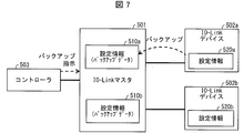
- FIG. 7 is a diagram illustrating a conventional technique, and is a diagram illustrating an overview of backup of setting information of an IO-Link device in an IO-Link system.
- the illustrated IO-Link system includes an IO-Link master 501 (corresponding to the aforementioned slave device), IO-Link devices 502a and 502b, and a controller 503 (corresponding to the aforementioned master device).
- IO-Link master 501 acquires the setting information 520a from the IO-Link device 502a and stores it as setting information 510a (backup data). The same applies to the IO-Link device 502b.
- a backup instruction addressed to the IO-Link device 502b is transmitted from the controller 503 to the IO-Link master 501, and the IO-Link master 501 acquires the setting information 520b from the IO-Link device 502b, and the setting information 510b (backup data)
- the IO-Link master 501 acquires the setting information 520b from the IO-Link device 502b, and the setting information 510b (backup data)
- a backup instruction to the IO-Link device is essential, and the processing when there are many IO-Link devices to be backed up becomes complicated. There was a problem. For example, when eight IO-Link devices are connected to one IO-Link master and all these backups are performed, the controller 503 has to perform the backup instruction eight times.
- Such a problem is not limited to the IO-Link system, and is a problem that commonly occurs in FA systems that can back up device setting information to a relay device such as a slave device.
- the present invention has been made in view of the above-described problems, and an object thereof is to realize a relay device or the like that can easily back up or restore setting information of a plurality of devices.
- a relay device relays data between a control device and a plurality of devices that are controlled by the control device and operate according to setting information
- An apparatus that receives a backup execution instruction for acquiring the setting information from the device and storing the setting information in a storage unit, or a restore execution instruction for transmitting the setting information stored in the storage unit to the device for storage A reception unit; and a setting information processing unit that executes backup of the plurality of devices or restores the plurality of devices according to one instruction received by the reception unit.
- a relay apparatus control method transmits data between a control apparatus and a plurality of devices that are controlled by the control apparatus and operate according to setting information.
- a method for controlling a relay device that relays, and that transmits the setting information acquired from the device and stores it in a storage unit or transmits the setting information stored in the storage unit to the device for storage A reception step for receiving a restore execution instruction, and a setting information processing step for executing backup of the plurality of devices or performing restoration of the plurality of devices in accordance with the one instruction received in the reception step; ,including.
- FIG. 1 It is a block diagram which shows an example of a principal part structure of the IO-Link master which concerns on Embodiment 1 of this invention. It is a figure which shows the outline
- Embodiment 3 of this invention is a figure which shows the example of the IO-Link system which disconnected the communication function with the high-order network in an IO-Link master as a communication coupler. It is a figure which shows a prior art and is a figure which shows the outline
- Embodiment 1 A first embodiment of the present invention will be described with reference to FIGS.
- FIG. 2 is a diagram showing an overview of the IO-Link system 9.
- the IO-Link system 9 is an FA system.
- the IO-Link system 9 includes an IO-Link master (relay device) 1, an IO-Link device 2a, an IO-Link device 2b, and a controller (control). Apparatus) 3, a support tool 4, and an HMI 5.
- IO-Link devices 2a and 2b these are expressed as IO-Link devices 2.
- the IO-Link master 1 is a relay device that relays data between the host network including the controller 3 and the IO-Link device 2, and operates as a slave device of the controller 3 in the IO-Link system 9.
- two IO-Link devices 2 are connected to the IO-Link master 1, but three or more IO-Link devices 2 can be connected.
- the IO-Link master 1 can communicate with the IO-Link device 2 bidirectionally.
- the IO-Link device 2 is a device that is connected to the IO-Link master 1 and is controlled by the controller 3.
- an output device and an input device can be applied.
- the input device include various sensors such as a photoelectric sensor and a proximity sensor.
- the output device include an actuator and a motor.
- a conversion device such as an inverter can also be used as the IO-Link device 2.
- the controller 3 is a control device that performs overall control of the IO-Link system 9 and is also called PLC (Programmable Logic Controller).
- the controller 3 operates as a master device of the IO-Link master 1 in the IO-Link system 9.
- the support tool 4 is a device used by connecting to the IO-Link system 9 for various settings in the IO-Link system 9 such as operation settings of the IO-Link device 2.
- the support tool 4 can be connected to the IO-Link system 9 via the controller 3.
- an information processing device such as a personal computer can be used, and a portable information processing device such as a notebook personal computer can also be used.
- the HMI 5 is a touch-panel display input device, and the user of the IO-Link system 9 may operate the controller 3 via the HMI 5 or check the operation state of the IO-Link system 9 via the HMI 5. it can.
- the IO-Link master 1 sets a plurality of IO-Link devices 2 in response to receiving one backup instruction from the controller 3 as shown in the figure. Back up the information 20 in a batch. More specifically, the IO-Link master 1 acquires the setting information 20a stored in the IO-Link device 2a from the IO-Link device 2a and stores it as backup data (setting information 111a). Further, the IO-Link master 1 acquires the setting information 20b stored in the IO-Link device 2b from the IO-Link device 2b and stores it as backup data (setting information 111b).
- setting information 111 when there is no need to distinguish between the setting information 111a and 111b, they are referred to as setting information 111. Similarly, when there is no need to distinguish between the setting information 20a and 20b, they are referred to as setting information 20.
- the setting information 20 is information indicating operation settings of the IO-Link device 2, and the IO-Link device 2 operates according to the setting information 20.
- a key lock setting that specifies whether or not to lock a setting by a hardware switch included in the photoelectric sensor, or ON when detecting light Outputs ON signal or OFF signal after satisfying LightON / DarkON setting that specifies whether to output signal or ON signal when light is not detected and ON signal or OFF signal output condition
- an ON (OFF) delay timer setting that defines a waiting time until the start is performed.
- the setting information 20 of the plurality of IO-Link devices 2 is backed up with one backup instruction, so that the setting information 20 of the plurality of IO-Link devices 2 can be easily backed up. it can.
- IO-Link is standardized under the name of “Single-drop digital communication interface for small sensors and actuators” (SDCI) in IEC 61131-9, and a master (the controller 3 corresponds to this) as a control device, A standardized technique for communication between devices such as sensors and actuators.
- SDCI single-drop digital communication interface for small sensors and actuators
- IO-Link is a new point-to-point serial communication protocol used for communication between masters and devices.
- An example of the device is a photoelectric sensor and a proximity switch.
- IO-Link is different from the conventional protocol that can only send on / off signals (1 bit) from the device to the master, and it can receive and send 32 bytes (256 bits) of data (bidirectional communication). It is a possible communication protocol.
- IO-Link By connecting the master and the device with IO-Link, a signal from a device that has conventionally received only binary data such as on / off information can be acquired as 32-byte numerical data. Therefore, for example, in the case of a photoelectric sensor, it becomes possible to acquire information such as the amount of received light, detection margin, internal temperature, etc., which is useful for investigating the cause of defects, as well as diagnosing product life and responding to deterioration over time.
- the threshold value can be changed.
- IO-Link By using IO-Link, for example, device settings and maintenance can be automated. Also, by using IO-Link, master programming can be greatly simplified, and the cost of wiring cables can be reduced.
- An IO-Link system consists of an IO-Link device (generally a sensor, actuator, or combination thereof, such as IO-Link device 2 above), a standard 3-wire sensor / actuator cable, and IO-Link And a master (the IO-Link master 1 corresponds to this).
- the IO-Link master has one or more ports (device communication port 12 described later corresponds to this), and one IO-Link device can be connected to each port.
- the IO-Link master performs point-to-point communication with the IO-Link device.
- the IO-Link master is not only binary data (1-bit data) such as conventional on / off information, but also device identification information, device communication properties, device parameters, and process / diagnostic data information, etc.
- Information other than binarized data (data larger than 1 bit) such as on / off information can be transmitted to and received from the IO-Link device.
- ⁇ IO-Link devices can send and receive data larger than 1 bit with the IO-Link master. That is, the IO-Link device is a device that conforms to IO-Link. In addition, devices such as sensors and actuators that are not IO-Link devices (not transmitting / receiving data larger than 1 bit) can be incorporated into the IO-Link system.
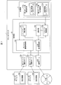
- FIG. 1 is a block diagram illustrating an example of a main configuration of the IO-Link master 1.
- the IO-Link master 1 includes a control unit 10 that controls each unit of the IO-Link master 1 and a storage unit 11 that stores various data used by the IO-Link master 1.
- the IO-Link master 1 includes a first device communication port 12a and a second device communication port 12b as communication ports for communicating with the IO-Link device 2.
- the IO-Link master 1 is provided with a host communication port 13 for communicating with a host network including the controller 3 described above. Note that when there is no need to distinguish between the first device communication port 12a and the second device communication port 12b, they are referred to as the device communication port 12.
- the number of device communication ports 12 may be three or more.
- the control unit 10 includes a device communication control unit 100, a higher-level communication control unit (reception unit) 101, a backup control unit (setting information processing unit) 102, a notification unit 103, and a restoration control unit (setting information processing unit) 104. It is included.
- the storage unit 11 includes a first port storage area 110a and a second port storage area 110b, and setting information 111a and 111b are stored in these storage areas, respectively. When there is no need to distinguish between the first port storage area 110a and the second port storage area 110b, they are referred to as the port storage area 110.
- the device communication control unit 100 controls communication with the IO-Link device 2.
- the upper communication control unit 101 controls communication with devices such as the controller 3 included in the upper network.
- the device communication control unit 100 accepts a backup instruction or a restore instruction from the upper network.
- Communication with the host network can be performed by, for example, EtherCAT (Ethernet Control Automation Technology: registered trademark).
- the backup control unit 102 controls backup of the setting information 20 stored in the IO-Link device 2. Specifically, the backup control unit 102 acquires the setting information 20 from the IO-Link device 2 and stores it as backup data (setting information 20) in the port storage area 110 corresponding to the IO-Link device 2. . The backup control unit 102 also performs a process of overwriting and updating the backup data with the setting information 20 acquired from the IO-Link device 2 that has already stored the backup data.
- the notification unit 103 When the backup processing by the backup control unit 102 is completed, the notification unit 103 notifies the upper network device to that effect. In addition, when there is an IO-Link device 2 for which backup or restoration has not ended normally, the notification unit 103 notifies the higher-level network device to that effect. Thereby, it is possible to make the user recognize the presence of the IO-Link device 2 whose backup or restoration has not been completed normally. Examples of higher-level network devices include the controller 3, the support tool 4, and the HMI 5.
- the restore control unit 104 sends the setting information 111 stored as backup data in the storage unit 11 to the IO-Link device 2 and updates the setting information 20 stored in the IO-Link device 2 Execute.
- the port storage area 110 is a storage area provided for each device communication port 12, and data related to each device communication port 12 is stored in the port storage area 110. Specifically, backup data (setting information) of the IO-Link device 2a connected to the first device communication port 12a is stored in the first port storage area 110a as data related to the first device communication port 12a. 111a) is stored. Similarly, backup data (setting information 111b) of the IO-Link device 2b connected to the second device communication port 12b is stored in the second port storage area 110b as data related to the second device communication port 12b. Is memorized.
- the backup timing is not particularly limited.
- the backup may be performed when the IO-Link system 9 is started up.
- each device constituting the IO-Link system 9 is connected by communication using a predetermined communication cable, and then initial setting of each device is performed.
- the initial setting can be performed via the support tool 4, and at the end of the initial setting, the setting information 20 is stored in the IO-Link device 2.
- the initial setting makes the IO-Link system 9 ready for operation. After the initial setting is completed, a trial run is performed to check whether the entire IO-Link system 9 is in the desired operating state. If there is a problem as a result of this confirmation, adjustments such as correction of the setting information 20 are performed, and the setting information 20 is backed up when the apparatus is operating without any problems.
- the setting information 20 can be corrected via the support tool 4, and the IO-Link device 2 having an input unit can also be corrected via the input unit.
- the backup is executed by the IO-Link master 1 by transmitting a backup instruction from the controller 3, the support tool 4 or the HMI 5 to the IO-Link master 1. Then, the start-up is completed by the end of the backup, and the IO-Link system 9 becomes operable.
- FIG. 3 is a diagram illustrating an example in which a backup instruction is transmitted from the host network to the IO-Link master 1.
- the backup instruction can be transmitted from the support tool 4 to the IO-Link master 1 via the controller 3 as shown in FIG. Further, as shown in FIG. 5B, a backup instruction can be transmitted from the HMI 5 to the IO-Link master 1 via the controller 3. Control that is irregularly performed in IO-Link, such as this backup instruction, is performed by transmitting a command in a predetermined format called a message.
- the message may be generated by the controller 3 or by the HMI 5 or the support tool 4.
- a backup instruction message may be generated by the support tool 4, and this may be relayed by the controller 3 and transmitted to the IO-Link master 1. Further, the controller 3 may generate a backup instruction message in response to a backup instruction from the support tool 4 to the controller 3 and transmit it to the IO-Link master 1. The same applies to the example of FIG.
- the source of the backup instruction is not limited to the above examples.
- a backup instruction can be directly transmitted to the IO-Link master 1 by the wireless communication function.
- a hardware key button, etc.
- a similar hardware key may be provided in the IO-Link device 2. In this case, the IO-Link device 2 notifies the IO-Link master 1 that the hardware key has been operated.
- the IO-Link master 1 may back up a plurality of IO-Link devices 2 including the IO-Link device 2 to be operated.
- the backup can be performed without using the support tool 4 or the like, so that the staff from the IO-Link system 9 installation site can smoothly perform the processing from the startup of the IO-Link system 9 to the backup. It becomes possible to perform simply.
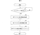
- FIG. 4 is a flowchart showing an example of backup processing (relay device control method) by the IO-Link master 1.
- the backup control unit 102 is waiting for a backup instruction (S1, reception step).
- a backup instruction is detected (YES in S1)
- the backup control unit 102 instructs the IO-Link device 2 connected to each device communication port 12 to transmit the setting information 20 (S2). ).
- each IO-Link device 2 transmits the setting information 20 to the IO-Link master 1 as a response to the instruction, the backup control unit 102 receives the setting information 20 (S3).
- the backup control unit 102 sets the received setting information 20 as setting information 111 in the port storage area 110 corresponding to the device communication port 12 to which the IO-Link device 2 that is the transmission source of the setting information 20 is connected.
- the notification unit 103 notifies that to the upper network device such as the backup instruction transmission source (support tool 4 or HMI 5) received by the controller 3 or S1. Then, the process ends.
- the backup for a plurality of IO-Link devices 2 may be performed concurrently or sequentially. Further, the backup may fail due to a communication error or the IO-Link device 2 not connected to the device communication port 12.
- the notification unit 103 may notify information (device identification information, device communication port 12 identification information, etc.) indicating the IO-Link device 2 that has failed to be backed up to a device in the upper network. If the reason for the backup failure is known, the reason may also be notified. As a result, it is possible to allow the user to recognize the existence of the IO-Link device 2 that failed to be backed up and the reason thereof on the HMI 5, for example.
- FIG. 5 is a diagram illustrating an example of the IO-Link master 1 that restores a plurality of IO-Link devices 2 in response to one restore instruction.
- the same reference number is attached
- the IO-Link master 1 transmits setting information 111 to each of the plurality of IO-Link devices 2 in response to receiving one restore instruction from the controller 3. Restore the setting information 20 of the IO-Link device 2. More specifically, the restore control unit 104 of the IO-Link master 1 transmits the setting information 111a to the IO-Link device 2a and stores it as the setting information 20a. Similarly, the restore control unit 104 transmits the setting information 111b to the IO-Link device 2b and stores it as the setting information 20b. If the setting information 20 is already stored, it is overwritten with the transmitted setting information 111.
- a plurality of IO-Link devices 2 are restored by one restore instruction, so that a plurality of IO-Link devices 2 can be easily restored. .
- a restore instruction may be input to the IO-Link master 1 from the support tool 4 or HMI 5 via the controller 3, or to the IO-Link master 1 without passing through other devices. It is also possible to send a restore instruction directly.
- the IO-Link master 1 has at least one of a function for restoring a plurality of IO-Link devices 2 with one restore instruction and a function for backing up a plurality of IO-Link devices 2 with one backup instruction. It only has to have.
- FIG. 6 is a diagram illustrating an example of the IO-Link system 92 in which the communication function with the host network in the IO-Link master is separated as a communication coupler.
- the illustrated IO-Link system 92 is a system having the same functions as the IO-Link system 9 described above, but instead of the IO-Link master 1 of the IO-Link system 9, a communication coupler 200 and an IO-Link master are provided. The difference is that 201 is provided.
- the communication coupler 200 is a relay device that relays communication between the host network and the IO-Link master 201.
- the communication coupler 200 includes a communication port corresponding to the host communication port 13 (see FIG. 1) of the IO-Link master 1 and a communication port for communicating with the IO-Link master 201.
- the communication coupler 200 includes a communication control unit corresponding to the upper communication control unit 101 (see FIG. 1) of the IO-Link master 1, and the communication control unit and the IO-Link master are included in the upper network. The communication is relayed to and from 201.
- the IO-Link master 201 has the same configuration as the IO-Link master 1 except that it includes a communication port for communicating with the communication coupler 200 instead of the host communication port 13 (see FIG. 1). Yes.
- a backup instruction is transmitted from the controller 3 in the same manner as the IO-Link system 9 described above, but this backup instruction is received by the IO-Link master 201 via the communication coupler 200. Note that the backup process after receiving the backup instruction is the same as that of the IO-Link master 1, and therefore the description thereof will not be repeated here.
- a backup instruction can be transmitted from the support tool 4 to the communication coupler 200 via the interface.
- the backup instruction is transferred from the communication coupler 200 to the IO-Link master 201.
- the IO-Link master 201 has an interface for connecting the support tool 4
- a backup instruction can be directly transmitted from the support tool 4 to the IO-Link master 201 via the interface.
- the IO-Link master 201 of the IO-Link system 92 restores a plurality of IO-Link devices 2 in response to receiving one restore instruction in the same manner as the IO-Link master 2 of the second embodiment. Can be done.
- the FA system using IO-Link has been described as an example.
- backup of a device is performed by a slave device, and bidirectional communication is performed between the device and the slave device. It can be applied to any FA system that can handle the above. For example, it can be applied to an FA system using CC-Link or the like.
- the slave device Backup and restoration may be performed collectively for these multiple devices.
- cyclic communication is performed at a predetermined cycle.
- the controller 3 transmits cyclic data to the IO-Link master 1, and the cyclic data is transmitted from the IO-Link master 1 to each IO-Link device 2.
- the cyclic data is returned from each IO-Link device 2 to the controller 3 via the IO-Link master 1.
- the cyclic data is shared among the devices constituting the IO-Link system 9.
- the IO-Link masters 1 and 201 may instruct backup and restoration by cyclic communication as described above.
- the IO-Link master 1 can perform a batch backup or a batch restore.
- a flag corresponding to the backup instruction and a flag corresponding to the restore instruction may be included in the cyclic data.
- the controller 3 switches the flag ON / OFF, whereby backup or restoration can be performed at the timing when the flag is turned ON.
- the backup instruction and the restore instruction may include designation information for designating a control target such as identification information of the target device communication port 12 and identification information of the IO-Link device 2.
- the backup control unit 102 backs up the device specified by the specified information
- the restore control unit 104 restores the device specified by the specified information.
- a plurality of backup and restoration targets can be specified, whereby backup and restoration of a plurality of IO-Link devices 2 can be performed easily and quickly.
- the backup control unit 102 may determine whether or not backup is necessary for each IO-Link device 2 to be backed up, and may only consider the IO-Link device 2 determined to be backed up. For example, backup valid / invalid settings for each device communication port 12 are stored in advance, and only the IO-Link device 2 connected to the device communication port 12 for which this setting is valid may be the backup target. Good.
- the IO-Link master 1 can be configured to determine whether or not the setting information 20 stored in the IO-Link device 2 matches the setting information 111 stored as backup data. May be provided. Then, when the backup unit is received within a predetermined time after the determination unit performs the determination, the IO-Link device 2 whose collation result does not match is targeted for backup and the IO-Link device whose collation result is the same. 2 may be excluded from the backup target.
- the above examples can be similarly applied to restoration.
- the control block of the IO-Link master 1 (particularly, each unit included in the control unit 10) may be realized by a logic circuit (hardware) formed in an integrated circuit (IC chip) or the like, or a CPU (Central Processing Unit) ) May be implemented by software.
- a logic circuit hardware
- IC chip integrated circuit
- CPU Central Processing Unit
- the IO-Link master 1 includes a CPU that executes instructions of a program that is software that implements each function, and a ROM (Read Only Memory) in which the program and various data are recorded so as to be readable by the computer (or CPU) ) Or a storage device (these are referred to as “recording media”), a RAM (Random Access Memory) that expands the program, and the like.
- the objective of this invention is achieved when a computer (or CPU) reads the said program from the said recording medium and runs it.
- a “non-temporary tangible medium” such as a tape, a disk, a card, a semiconductor memory, a programmable logic circuit, or the like can be used.
- the program may be supplied to the computer via an arbitrary transmission medium (such as a communication network or a broadcast wave) that can transmit the program.
- the present invention can also be realized in the form of a data signal embedded in a carrier wave in which the program is embodied by electronic transmission.
- the control block of apparatuses, such as IO-Link master 201 and the communication coupler 200, can also be implement
- a relay device is a relay device that relays data between a control device and a plurality of devices that are controlled by the control device and operate according to setting information.
- a receiving unit that receives a backup execution instruction for acquiring setting information and storing the setting information in a storage unit, or a restore execution instruction for transmitting the setting information stored in the storage unit to the device for storage, and the reception unit
- a setting information processing unit that executes backup of the plurality of devices or restores the plurality of devices in response to a single instruction.
- the setting information processing unit may execute backup of the device specified by the specification information when the specification information specifying the device is included in the one instruction received by the reception unit, or The device specified by the specification information may be restored.
- setting information of a specified device among a plurality of devices can be backed up, or setting information can be restored to the specified device.
- the relay apparatus may include a notification unit that notifies a user of a device in which backup or restoration has not been normally completed among the plurality of devices that the setting information processing unit has been subjected to backup or restoration. Good.
- the device may be an IO-Link device. Since many IO-Link devices are often connected to one relay device and used, it is possible to easily back up and restore the setting information of such many IO-Link devices. The benefits are particularly great.
- the relay apparatus control method is a relay apparatus control method that relays data between a control apparatus and a plurality of devices that are controlled by the control apparatus and operate according to setting information. And accepting a backup execution instruction for acquiring the setting information from the device and storing it in a storage unit, or a restore execution instruction for transmitting the setting information stored in the storage unit to the device for storage And a setting information processing step for executing backup of the plurality of devices or restoring of the plurality of devices according to one instruction received in the receiving step. According to the control method, the same operation and effect as the above-described relay device are achieved.
- control program for causing a computer to function as the relay device by causing the computer to execute the above steps and a computer-readable recording medium on which the control program is recorded are also included in the scope of the present invention.
- IO-Link master (relay device) 11 Storage Unit 101 Host Communication Control Unit (Reception Unit) 102 Backup control unit (setting information processing unit) 103 Notification unit 104 Restore control unit (setting information processing unit) 111 Setting information (backup data) 2 IO-Link device (device) 20 Setting information 3 Controller (control device) 201 IO-Link master (relay device)
Landscapes
- Engineering & Computer Science (AREA)
- Physics & Mathematics (AREA)
- General Physics & Mathematics (AREA)
- Automation & Control Theory (AREA)
- General Engineering & Computer Science (AREA)
- Manufacturing & Machinery (AREA)
- Quality & Reliability (AREA)
- Programmable Controllers (AREA)
- Information Retrieval, Db Structures And Fs Structures Therefor (AREA)
Priority Applications (3)
| Application Number | Priority Date | Filing Date | Title |
|---|---|---|---|
| CN201680047276.2A CN107924168B (zh) | 2016-03-14 | 2016-12-06 | 中转装置、中转装置的控制方法以及可读取记录媒体 |
| US15/751,478 US11067969B2 (en) | 2016-03-14 | 2016-12-06 | Relay device for relaying data between devices, control method therefor, and non-transitory computer-readable recording medium therefor |
| EP16894571.5A EP3432096B1 (de) | 2016-03-14 | 2016-12-06 | Relaisvorrichtung, steuerungsverfahren für relaisvorrichtung, steuerungsprogramm und aufzeichnungsmedium |
Applications Claiming Priority (2)
| Application Number | Priority Date | Filing Date | Title |
|---|---|---|---|
| JP2016049318A JP6477555B2 (ja) | 2016-03-14 | 2016-03-14 | 中継装置、中継装置の制御方法、制御プログラム、および記録媒体 |
| JP2016-049318 | 2016-03-14 |
Publications (1)
| Publication Number | Publication Date |
|---|---|
| WO2017158954A1 true WO2017158954A1 (ja) | 2017-09-21 |
Family
ID=59851819
Family Applications (1)
| Application Number | Title | Priority Date | Filing Date |
|---|---|---|---|
| PCT/JP2016/086255 Ceased WO2017158954A1 (ja) | 2016-03-14 | 2016-12-06 | 中継装置、中継装置の制御方法、制御プログラム、および記録媒体 |
Country Status (5)
| Country | Link |
|---|---|
| US (1) | US11067969B2 (de) |
| EP (1) | EP3432096B1 (de) |
| JP (1) | JP6477555B2 (de) |
| CN (1) | CN107924168B (de) |
| WO (1) | WO2017158954A1 (de) |
Families Citing this family (9)
| Publication number | Priority date | Publication date | Assignee | Title |
|---|---|---|---|---|
| WO2019045011A1 (ja) | 2017-08-31 | 2019-03-07 | 国立大学法人京都大学 | 水酸化脂肪酸のホモポリマーとその製造方法 |
| JP7183545B2 (ja) * | 2018-02-27 | 2022-12-06 | オムロン株式会社 | 制御システムおよび機能ユニット |
| JP6628934B1 (ja) * | 2018-03-30 | 2020-01-15 | 三菱電機株式会社 | センサ管理装置、センサ管理方法及びプログラム |
| CN108449250B (zh) * | 2018-05-22 | 2023-08-04 | 三明学院 | 一种支持多总线的io-link主站装置及方法 |
| CN114144736B (zh) * | 2019-07-25 | 2023-05-30 | 三菱电机株式会社 | 生产辅助装置、生产系统及记录介质 |
| JP7409887B2 (ja) | 2020-01-23 | 2024-01-09 | 株式会社キーエンス | データ中継装置および表示装置 |
| CN113285905A (zh) * | 2020-02-19 | 2021-08-20 | 台达电子工业股份有限公司 | 跨协定控制设备及其跨协定的设备还原方法 |
| CN112738224B (zh) * | 2020-12-29 | 2022-06-10 | 浙江中控技术股份有限公司 | 一种支持触发式通信的数据处理系统和方法 |
| DE102021133338A1 (de) * | 2021-12-15 | 2023-06-15 | Balluff Gmbh | Verfahren zur Überwachung mittels maschinellem Lernen |
Citations (3)
| Publication number | Priority date | Publication date | Assignee | Title |
|---|---|---|---|---|
| JPS5927311A (ja) * | 1982-08-03 | 1984-02-13 | Fanuc Ltd | 作業セルコントロ−ラ |
| JP2011180863A (ja) * | 2010-03-02 | 2011-09-15 | Trinity Security Systems Inc | バックアップシステム、バックアップ方法およびバックアッププログラム |
| JP2014174616A (ja) | 2013-03-06 | 2014-09-22 | Mitsubishi Electric Corp | Faシステムおよび制御装置 |
Family Cites Families (23)
| Publication number | Priority date | Publication date | Assignee | Title |
|---|---|---|---|---|
| US5566349A (en) * | 1994-05-16 | 1996-10-15 | Trout; Ray C. | Complementary concurrent cooperative multi-processing multi-tasking processing system using shared memories with a minimum of four complementary processors |
| US5968115A (en) * | 1997-02-03 | 1999-10-19 | Complementary Systems, Inc. | Complementary concurrent cooperative multi-processing multi-tasking processing system (C3M2) |
| US20030158635A1 (en) * | 1999-07-30 | 2003-08-21 | Oshkosh Truck Corporation | Firefighting vehicle with network-assisted scene management |
| US7098069B2 (en) * | 2002-01-24 | 2006-08-29 | Semiconductor Energy Laboratory Co., Ltd. | Light emitting device, method of preparing the same and device for fabricating the same |
| US20080155215A1 (en) * | 2005-01-21 | 2008-06-26 | Natsume Matsuzaki | Backup System, Relay Device, Information Terminal, and Backup Device |
| JP4415981B2 (ja) * | 2005-09-09 | 2010-02-17 | オムロン株式会社 | プログラマブル・コントローラのリモートターミナル装置 |
| CN201796357U (zh) * | 2009-07-15 | 2011-04-13 | 王颖 | 系统备份还原装置 |
| DE102010010014B3 (de) * | 2010-03-03 | 2011-04-21 | Sick Ag | Sicherheitsvorrichtung mit einer konfigurierbaren Sicherheitssteuerung |
| CN101969456B (zh) * | 2010-09-17 | 2014-10-01 | 深圳市融创天下科技股份有限公司 | 一种地图显示系统和方法 |
| DE102012014682B4 (de) * | 2012-05-29 | 2017-02-09 | Balluff Gmbh | Feldbussystem |
| JP5652444B2 (ja) * | 2012-08-31 | 2015-01-14 | 横河電機株式会社 | 保守支援システム及び方法 |
| CN103873344A (zh) * | 2012-12-14 | 2014-06-18 | 高海军 | 一种可编辑联系人的联系信息的即时通讯软件 |
| JP6167532B2 (ja) * | 2013-01-25 | 2017-07-26 | オムロン株式会社 | 制御装置および制御装置の動作方法 |
| US9064125B2 (en) * | 2013-05-03 | 2015-06-23 | Citrix Systems, Inc. | Image analysis and management |
| JP5943022B2 (ja) * | 2014-03-25 | 2016-06-29 | 横河電機株式会社 | プロセス制御システム |
| US9729520B2 (en) * | 2014-05-05 | 2017-08-08 | Citrix Systems, Inc. | Facilitating communication between mobile applications |
| DE102014106752B4 (de) * | 2014-05-13 | 2022-09-29 | Balluff Gmbh | Verfahren und Steuereinrichtung zum Betrieb eines berührungslosen Übertragungssystems für einen IO-Link |
| CN104615507A (zh) * | 2015-02-13 | 2015-05-13 | 广东欧珀移动通信有限公司 | 备份数据的批量还原方法和装置 |
| US9971344B2 (en) * | 2015-03-27 | 2018-05-15 | Rockwell Automation Technologies, Inc. | Systems and methods for assessing a quality of an industrial enterprise |
| US10254749B2 (en) * | 2015-03-27 | 2019-04-09 | Rockwell Automation Technologies, Inc. | Systems and methods for virtually tagging and securing industrial equipment |
| US10547666B2 (en) * | 2015-03-27 | 2020-01-28 | Rockwell Automation Technologies, Inc. | Systems and methods for exchanging information between devices in an industrial automation environment |
| US9804855B1 (en) * | 2015-10-08 | 2017-10-31 | Veritas Technologies Llc | Modification of temporary file system for booting on target hardware |
| JP6638489B2 (ja) * | 2016-03-14 | 2020-01-29 | オムロン株式会社 | 中継装置、中継装置の制御方法、制御プログラム、および記録媒体 |
-
2016
- 2016-03-14 JP JP2016049318A patent/JP6477555B2/ja not_active Expired - Fee Related
- 2016-12-06 CN CN201680047276.2A patent/CN107924168B/zh not_active Expired - Fee Related
- 2016-12-06 EP EP16894571.5A patent/EP3432096B1/de not_active Not-in-force
- 2016-12-06 US US15/751,478 patent/US11067969B2/en not_active Expired - Fee Related
- 2016-12-06 WO PCT/JP2016/086255 patent/WO2017158954A1/ja not_active Ceased
Patent Citations (3)
| Publication number | Priority date | Publication date | Assignee | Title |
|---|---|---|---|---|
| JPS5927311A (ja) * | 1982-08-03 | 1984-02-13 | Fanuc Ltd | 作業セルコントロ−ラ |
| JP2011180863A (ja) * | 2010-03-02 | 2011-09-15 | Trinity Security Systems Inc | バックアップシステム、バックアップ方法およびバックアッププログラム |
| JP2014174616A (ja) | 2013-03-06 | 2014-09-22 | Mitsubishi Electric Corp | Faシステムおよび制御装置 |
Non-Patent Citations (1)
| Title |
|---|
| See also references of EP3432096A4 |
Also Published As
| Publication number | Publication date |
|---|---|
| JP2017167595A (ja) | 2017-09-21 |
| CN107924168B (zh) | 2021-08-03 |
| JP6477555B2 (ja) | 2019-03-06 |
| CN107924168A (zh) | 2018-04-17 |
| EP3432096A4 (de) | 2019-11-20 |
| US11067969B2 (en) | 2021-07-20 |
| EP3432096B1 (de) | 2022-08-17 |
| EP3432096A1 (de) | 2019-01-23 |
| US20180196410A1 (en) | 2018-07-12 |
Similar Documents
| Publication | Publication Date | Title |
|---|---|---|
| JP6477555B2 (ja) | 中継装置、中継装置の制御方法、制御プログラム、および記録媒体 | |
| JP6638489B2 (ja) | 中継装置、中継装置の制御方法、制御プログラム、および記録媒体 | |
| US10419237B2 (en) | Slave device, control method of slave device, information processing program and recording medium | |
| JP6874438B2 (ja) | スレーブ装置、スレーブ装置の制御方法、情報処理プログラム、および記録媒体 | |
| JP6717026B2 (ja) | 制御装置、中継装置、制御装置の制御方法、中継装置の制御方法、制御プログラム、および記録媒体 | |
| EP3428750B1 (de) | Slave-vorrichtung, verfahren zur steuerung der slave-vorrichtung, informationsverarbeitungsprogramm und aufzeichnungsmedium | |
| WO2017154273A1 (ja) | マスタースレーブ制御システム、マスタースレーブ制御システムの制御方法、情報処理プログラム、および記録媒体 | |
| JP6477554B2 (ja) | 中継装置、中継装置の制御方法、制御プログラム、および記録媒体 | |
| CN108369403A (zh) | 现场总线耦合器、系统和用于配置故障保险模块的方法 | |
| CN106170738A (zh) | 现场总线模块、机器控制装置和用于对尤其是面向安全的现场总线模块进行参数化的方法 | |
| JP2020147250A (ja) | 電子制御装置 | |
| JP2016054367A (ja) | マスター・スレーブネットワーク装置 | |
| WO2022190186A1 (ja) | プログラマブルコントローラの通信ユニット、受信データ記憶方法及びプログラム | |
| CN114127646B (zh) | 支持装置、支持程序的记录介质及设定方法 | |
| JP2025141027A (ja) | セーフティデバイス | |
| JPH09149476A (ja) | バンプレスプロセスコントローラ | |
| JP2000339234A (ja) | バス故障箇所特定装置およびバス故障箇所特定方法 |
Legal Events
| Date | Code | Title | Description |
|---|---|---|---|
| NENP | Non-entry into the national phase |
Ref country code: DE |
|
| 121 | Ep: the epo has been informed by wipo that ep was designated in this application |
Ref document number: 16894571 Country of ref document: EP Kind code of ref document: A1 |