WO2017159069A1 - Dispositif d'entraînement de bobine d'actionnement pour contacteur électromagnétique - Google Patents
Dispositif d'entraînement de bobine d'actionnement pour contacteur électromagnétique Download PDFInfo
- Publication number
- WO2017159069A1 WO2017159069A1 PCT/JP2017/002965 JP2017002965W WO2017159069A1 WO 2017159069 A1 WO2017159069 A1 WO 2017159069A1 JP 2017002965 W JP2017002965 W JP 2017002965W WO 2017159069 A1 WO2017159069 A1 WO 2017159069A1
- Authority
- WO
- WIPO (PCT)
- Prior art keywords
- coil
- unit
- determination
- contact
- control
- Prior art date
- Legal status (The legal status is an assumption and is not a legal conclusion. Google has not performed a legal analysis and makes no representation as to the accuracy of the status listed.)
- Ceased
Links
Images



Classifications
-
- H—ELECTRICITY
- H01—ELECTRIC ELEMENTS
- H01H—ELECTRIC SWITCHES; RELAYS; SELECTORS; EMERGENCY PROTECTIVE DEVICES
- H01H47/00—Circuit arrangements not adapted to a particular application of the relay and designed to obtain desired operating characteristics or to provide energising current
- H01H47/22—Circuit arrangements not adapted to a particular application of the relay and designed to obtain desired operating characteristics or to provide energising current for supplying energising current for relay coil
- H01H47/32—Energising current supplied by semiconductor device
- H01H47/325—Energising current supplied by semiconductor device by switching regulator
-
- H—ELECTRICITY
- H01—ELECTRIC ELEMENTS
- H01F—MAGNETS; INDUCTANCES; TRANSFORMERS; SELECTION OF MATERIALS FOR THEIR MAGNETIC PROPERTIES
- H01F7/00—Magnets
- H01F7/06—Electromagnets; Actuators including electromagnets
- H01F7/08—Electromagnets; Actuators including electromagnets with armatures
- H01F7/18—Circuit arrangements for obtaining desired operating characteristics, e.g. for slow operation, for sequential energisation of windings, for high-speed energisation of windings
- H01F7/1844—Monitoring or fail-safe circuits
-
- H—ELECTRICITY
- H01—ELECTRIC ELEMENTS
- H01H—ELECTRIC SWITCHES; RELAYS; SELECTORS; EMERGENCY PROTECTIVE DEVICES
- H01H47/00—Circuit arrangements not adapted to a particular application of the relay and designed to obtain desired operating characteristics or to provide energising current
- H01H47/22—Circuit arrangements not adapted to a particular application of the relay and designed to obtain desired operating characteristics or to provide energising current for supplying energising current for relay coil
- H01H47/223—Circuit arrangements not adapted to a particular application of the relay and designed to obtain desired operating characteristics or to provide energising current for supplying energising current for relay coil adapted to be supplied by AC
-
- H—ELECTRICITY
- H01—ELECTRIC ELEMENTS
- H01H—ELECTRIC SWITCHES; RELAYS; SELECTORS; EMERGENCY PROTECTIVE DEVICES
- H01H47/00—Circuit arrangements not adapted to a particular application of the relay and designed to obtain desired operating characteristics or to provide energising current
- H01H47/22—Circuit arrangements not adapted to a particular application of the relay and designed to obtain desired operating characteristics or to provide energising current for supplying energising current for relay coil
- H01H47/32—Energising current supplied by semiconductor device
-
- F—MECHANICAL ENGINEERING; LIGHTING; HEATING; WEAPONS; BLASTING
- F02—COMBUSTION ENGINES; HOT-GAS OR COMBUSTION-PRODUCT ENGINE PLANTS
- F02D—CONTROLLING COMBUSTION ENGINES
- F02D41/00—Electrical control of supply of combustible mixture or its constituents
- F02D41/20—Output circuits, e.g. for controlling currents in command coils
- F02D2041/202—Output circuits, e.g. for controlling currents in command coils characterised by the control of the circuit
- F02D2041/2058—Output circuits, e.g. for controlling currents in command coils characterised by the control of the circuit using information of the actual current value
-
- H—ELECTRICITY
- H01—ELECTRIC ELEMENTS
- H01F—MAGNETS; INDUCTANCES; TRANSFORMERS; SELECTION OF MATERIALS FOR THEIR MAGNETIC PROPERTIES
- H01F7/00—Magnets
- H01F7/06—Electromagnets; Actuators including electromagnets
- H01F7/08—Electromagnets; Actuators including electromagnets with armatures
- H01F7/18—Circuit arrangements for obtaining desired operating characteristics, e.g. for slow operation, for sequential energisation of windings, for high-speed energisation of windings
- H01F7/1844—Monitoring or fail-safe circuits
- H01F2007/1861—Monitoring or fail-safe circuits using derivative of measured variable
Definitions
- the present invention relates to an operation coil drive device for an electromagnetic contactor that opens and closes a current supplied to an electric load device such as an electric motor.
- the electromagnetic contactor generates a suction force for attracting the movable iron core to the fixed iron core by energization of the operation coil constituting the electromagnet device, and brings the movable contact into contact with and away from the fixed contact. This opens and closes the electric circuit between the single-phase power source or the three-phase power source and the load device.
- Various proposals have conventionally been made for coil drive circuits used in electromagnetic contactors (see, for example, Patent Documents 1 to 3).
- a semiconductor switching element for supplying a power supply voltage to an operation coil, a voltage detection circuit for detecting the power supply voltage, and a setting level signal corresponding to the detection voltage of the voltage detection circuit are output and set.
- a gain circuit that outputs a holding level signal higher than the input level signal after time based on the detected voltage, a reference wave generating circuit that generates a sawtooth wave, a sawtooth wave of the reference wave generating circuit, and the gain circuit And comparing the sawtooth wave with the holding level signal after the output set time and comparing the sawing pulse signal with the holding level signal, and the on / off time ratio (both the duty ratio).
- a comparator that outputs a small holding pulse signal, and a pulse output that supplies the input pulse signal and holding pulse signal of the comparison circuit to the semiconductor switching element.
- Patent Document 1 a large attractive force is required at the time of closing control in which the iron core gap of the electromagnet is large (that is, the fixed contact and the movable contact are separated), so that the coil is excited with a large current,
- the iron core gap of the electromagnet is large (that is, the fixed contact and the movable contact are separated)
- the coil is excited with a large current
- the voltage applied to the operation coil when the electromagnetic relay is driven is integrated by an integration circuit using a capacitor and a resistor, and the applied voltage is reduced after the time based on the time constant of the integration circuit to reduce the power for driving the operation coil.
- the integration circuit here integrates the voltage applied to the electromagnetic relay with an arbitrarily set capacitor and resistance, and does not detect the operation of the operation coil of the electromagnetic relay. It is a timed circuit for setting the time.
- An electromagnet device having a flow means is disclosed.
- the conventional electromagnetic contactor operating coil driving device has the following problems. Normally, when the electromagnetic contactor changes from an off state to an on state, a large coil current is passed to move the movable iron core from the released state to the attracted state, and when the attracted state is reached, the operating coil current is reduced. It has been switched to.
- a control operation switching method a method using a position sensor for detecting the state of adsorption of the movable core or a method using a timer set in accordance with the time until the adsorption of the movable core is employed.
- the operation is reliable, but a sensor for detecting the iron core position is separately required.
- the time until the movable iron core is attracted varies depending on fluctuations in power supply voltage, changes in ambient temperature, fluctuations in coil resistance due to temperature conversion caused by self-heating of the operation coil, and influences on the mounting direction of the magnetic contactor.
- the timer period for switching the control operation is sufficiently longer than the core attracting time. Will be set.
- the attractive force of the operation coil is generally reduced by adjusting the power supply voltage to be applied.
- the operating coil current during the closing control and holding control is affected by fluctuation factors other than the power supply voltage, such as variations in coil resistance values and changes in coil resistance due to coil temperature rise. The reality is that it has not been obtained.
- the present invention has been made paying attention to the problems of the conventional example described above, and an operation coil drive device for an electromagnetic contactor that can reliably detect the attracting state of the movable core without using a position sensor or a timer.
- the purpose is to provide.
- an operation coil drive device for an electromagnetic contactor has a movable contact arranged so as to be able to contact and separate with respect to a fixed contact, and moves the movable contact.
- An electromagnetic contactor that switches and applies power supply voltage to an operation coil wound around a fixed iron core that attracts the movable iron core, a current detection unit that detects a coil current flowing through the operation coil by switching control, and a power supply to the operation coil
- a drive control unit for controlling the on / off time ratio of the semiconductor switching element, which is applied by switching the voltage, to be larger than that during the holding control during the closing control.
- the drive control unit includes a determination trajectory setting unit that sets a determination trajectory that continuously increases along the change trajectory of the coil current detected by the current detection unit during the closing control, and the determination trajectory setting unit.
- a closed state determination unit that determines a contact closed state by contact of the movable contact with the fixed contact based on a deviation between the determination locus and the coil current detected by the current detection unit;
- the contact closed state due to the contact of the movable contact with the fixed contact can be ensured without using a position sensor or a timer. Can be detected.
- FIG. 4 is a block diagram illustrating a specific configuration of a drive control unit in FIG. 3.
- FIG. 5 is a functional block diagram of the arithmetic processing circuit in FIG. 4. It is a flowchart which shows an example of the coil drive control processing procedure performed with the drive control part of FIG. It is a signal waveform diagram which shows operation
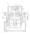
- an electromagnetic contactor 10 applicable to the present invention includes a lower case 11 made of an insulating material, an upper case 12 made of an insulating material mounted on the upper portion of the lower case 11, and an upper case 12. And an arc extinguishing cover 13 made of an insulating material that covers and covers the upper opening.
- a pair of left and right fixed contacts 15A and 15B and terminal plates 16A and 16B are fixed to the intermediate wall of the upper case 12 at a predetermined interval.
- the fixed contact 15A and the terminal plate 16A are connected to an external power supply 17, and the fixed contact 15B and the terminal plate 16B are connected to a load device 18 such as an inverter that drives an electric device such as an electric motor.
- An electromagnet device 21 is accommodated in the space of the lower case 11 and the lower space of the space below the intermediate wall of the upper case 12.
- the electromagnet device 21 includes a pair of left and right fixed iron cores 21a and 21b, an operation coil 21d wound around the outer circumference of one fixed iron core 21a via a coil holder 21c, and a coil holder 21c on the outer circumference of the other fixed iron core 21b.
- the movable contact mechanism 22 is housed in an internal space that sandwiches the intermediate wall portion of the upper case 12.
- the movable contact mechanism 22 includes a contact support 23 and a connecting portion 24 that fixes the movable iron core 21 i of the electromagnet device 21, and is connected to an upper portion of the movable contact holder 25.
- a single plate-like movable contact 26 facing the fixed contacts 15A and 15B from above, and an upper portion of the contact support 23, and a spring biasing force is applied downward to the movable contact 26.
- a plurality of contact pressure springs 27 are provided, and a plurality of return springs 28 are arranged between the magnetic pole plates 21g and 21h and the connecting portion 24 and bias the movable iron core 21i away from the fixed iron cores 21a and 21b.
- the electromagnetic contactor 10 having the above-described configuration has a current flowing in the operation coils 21d and 21e of the fixed iron cores 21a and 21b in an open state in which the movable contact 26 is spaced upward from the fixed contacts 15A and 15B shown in FIG.
- Due to the strong magnetic flux generated in the fixed iron cores 21a and 21b an attractive force to the movable iron core 21i is generated in the fixed iron cores 21a and 21b.
- the attractive force is proportional to the product of the coil current flowing through the operation coils 21d and 21e and the number of windings wound around the operation coils 21d and 21e.
- the movable iron core 21i is attracted downward by a suction force generated in the fixed iron cores 21a and 21b after a certain period of time after the operation coils 21d and 21e are started to be driven, and as shown in FIG. 15B is contacted by the contact pressure of the contact pressure spring 27. For this reason, the magnetic contactor 10 is in a closed state, and the electric power from the external power supply 17 is supplied to the load device 18. Further, the electromagnetic contactor 10 incorporates an operation coil driving device 30 shown in FIG. 3 in order to flow current to the operation coils 21d and 21e.
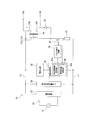
- the operation coil drive device 30 includes a rectifier circuit 33 to which a coil power source 31 that is a single-phase AC power source or a three-phase AC power source is connected via an operation switch 32.
- the operation switch 32 is controlled by a switching signal from the outside that controls the electromagnetic contactor 10 to an on state (closed state) and an off state (open state).
- the rectifier circuit 33 includes a number of rectifier diodes or the like corresponding to the type of the coil power supply 31, and supplies a DC voltage obtained by rectifying an AC voltage to the following circuits via the positive electrode side line Lp and the negative electrode side line Ln.
- the operation coil driving device 30 includes an input voltage detection circuit 34 connected between the positive electrode side line Lp and the negative electrode side line Ln of the rectifier circuit 33 and a power supply circuit 35 connected between the positive electrode side line Lp and the negative electrode side line Ln. And a drive control unit 36.
- the input voltage detection circuit 34 detects the output voltage of the rectifier circuit 33 using, for example, voltage dividing means using a resistance element, and supplies it to the drive control unit 36.
- the power supply circuit 35 is configured by, for example, a voltage regulator circuit, and converts the DC high voltage output from the rectifier circuit 33 into a DC low voltage used by the drive control unit 36.
- the power supply circuit 35 can be omitted.
- the operating coil driving device 30 includes a semiconductor switching element 40 connected in series with the operating coils 21d and 21e of the electromagnetic contactor 10 connected in series between the positive line Lp and the negative line Ln of the rectifier circuit 33. And a current detection resistor element 41. That is, one end of the operation coils 21d and 21e connected in series is connected to the positive electrode side line Lp of the rectifier circuit 33, and the high potential side electrode of the semiconductor switching element 40 is connected to the other end of the operation coils 21d and 21e. It is connected.
- a current detection resistor element 41 is connected between the low potential side electrode of the semiconductor switching element 40 and the negative electrode side line Ln.
- the operation coil drive device 30 includes a pulse generation circuit 39 connected to the control electrode of the semiconductor switching element 40.
- the duty ratio signal S Duty output from the drive control unit 36 is input to the pulse generation circuit 39.
- a diode element 42 constituting a reflux circuit is connected in parallel to the operation coils 21d and 21e.
- the operation coil drive device 30 having the above configuration is a circuit that appropriately controls the coil current supplied to the operation coils 21 d and 21 e of the electromagnet device 21.
- the operation coil drive device 30 generally drives the operation coils 21d and 21e so that the movable iron core 21i is attracted to the fixed iron cores 21a and 21b, and further, the operation coils 21d and 21e maintain the attracted state. Drive.
- the semiconductor switching element 40 can be realized by, for example, a MOS-FET (Metal Oxide Semiconductor-Field Effect Transistor) or a bipolar transistor. In the case of an N-type MOS-FET, the control electrode of the semiconductor switching element 40 is used as a gate terminal. The high potential side electrode corresponds to the drain terminal, and the low potential side electrode corresponds to the source terminal.
- MOS-FET Metal Oxide Semiconductor-Field Effect Transistor
- the semiconductor switching element 40 switches the output DC voltage of the rectifier circuit 33 by an on / off pulse signal from the pulse generation circuit 39. As a result, a coil current flows through the operation coils 21d and 21e. At this time, a voltage obtained by subtracting the saturation voltage of the semiconductor switching element 40 and the voltage across the current detection resistor element 41 from the output voltage of the rectifier circuit 33 is generated at both terminals of the operation coils 21d and 21e.
- the semiconductor switching element 40 an element whose saturation voltage is sufficiently smaller than the output voltage of the rectifier circuit 33 is selected as the semiconductor switching element 40. Thereby, element damage due to the influence of the package thermal resistance of the semiconductor switching element can be prevented.
- the current sensing resistor element 41 is operated coil 21d when turned pulse, to withstand the large current flowing in 21e, the resistance ⁇ current 2 considering package heat-resistant temperature of the current detecting resistor element 41 to select the minute resistance value . Further, a resistance value that is sufficiently smaller than the output voltage of the rectifier circuit 33 is selected for the both-terminal voltage of the current detection resistor element 41.
- the semiconductor switching element 40 switches the output DC voltage of the rectifier circuit 33 by the on / off pulse signal supplied from the pulse generation circuit 39. As a result, a coil current flows through the operation coils 21d and 21e. The magnitude of the coil current is determined by the power supply voltage, the resistance values and inductance values of the operation coils 21d and 21e, and the on-time of the semiconductor switching element 40.
- the current detection resistance element 41 detects the coil current flowing through the operation coils 21 d and 21 e and outputs it to the drive control unit 36.
- the drive control unit 36 performs closing control for attracting the movable iron core 21i to the fixed iron cores 21a and 21b, holding control for maintaining the attracted state thereafter, and opening control for releasing the movable iron core 21i from the fixed iron cores 21a and 21b.
- the specific configuration of the drive control unit 36 accurately measures fluctuation factors other than the power supply voltage such as variations in resistance values of the operation coils 21d and 21e and changes in the operation coil resistance due to a rise in coil temperature.
- an arithmetic processing circuit 36a composed of, for example, a microprocessor is mounted.
- the drive control unit 36 includes an analog / digital converter (hereinafter referred to as ADC) 36b that converts a coil current, which is an analog voltage input from the current detection resistor element 41, into a digital signal. Further, the drive control unit 36 is equipped with at least two first timers 36c and second timers 36d in order that the arithmetic processing circuit 36a and the pulse generation circuit 39 have a pulse width modulation (PWM) control function. Of these, the first timer 36c is used as a timer for determining the PWM period, and it is desirable that the period exceeds the tens of KHz outside the audible frequency.
- ADC analog / digital converter
- the second timer 36d is used to determine the time for turning on the semiconductor switching element 40 and exciting the operation coils 21d and 21e.
- the on / off time ratio (or duty ratio) for exciting the operation coils 21d and 21e determined by the first timer 36c is set to be large during the closing control with respect to the PWM cycle determined during the closing control. Set smaller when holding control.
- the drive control unit 36 includes a nonvolatile memory 36e connected to the arithmetic processing circuit 36a.
- the nonvolatile memory 36e stores a control map that represents a determination trajectory described later.
- the specific configuration of the arithmetic processing circuit 36 a includes an input processing unit 51, a setting processing unit 52, a PID control processing unit 53, and a closed circuit state determination unit 54 as shown in FIG. 5. ing.
- the input processing unit 51 includes a current input unit 51a and a moving average calculation unit 51b.
- Current input portion 51a is set, for example sampling period to 20 kHz, the coil current detection value I FB analog voltage output from the current sensing resistor elements 41 in every sampling period, it captures via ADC36b.
- Moving average calculation unit 51b the moving average of 20 pieces of the coil current detection value I FB input from the current input section 51a. Therefore, the moving average value of the coil current is output as the coil current measurement value PV (k) from the moving average calculation unit 51b every 1 kHz.
- the setting processing unit 52 includes a determination trajectory setting unit 52a used for closing control, a holding control setting unit 52b used for holding control, and a selection switch 52c.
- the determination trajectory setting unit 52a refers to the closing drive pattern representing the current change trajectory corresponding to the trajectory of the coil current flowing through the operation coils 21d and 21e during the closing control, and sets the coil current set value as the coil current set value SV. Output.
- the holding control setting unit 52b outputs a holding control coil current setting value having a constant current value as the coil current setting value SV during holding control.
- the selection switch 52c selects the determination trajectory setting unit 52a when the selection signal SL from the closed state determination unit 54 described later is at a high level, and selects the holding control setting unit 52b when the selection signal is at a low level. Select and output to the PID control processing unit 53.
- the PID control processing unit 53 includes a subtractor 53a, a PID calculation unit 53b, and a drive signal forming unit 53c.
- the subtractor 53a receives the coil current measurement value PV (k) output from the input processing unit 51 and the coil current set value SV (k) output from the setting processing unit 52, and the coil current set value SV ( The current deviation DV (k) k is calculated by subtracting the coil current measurement value PV (k) from k), and the calculated current deviation DV (k) is output to the PID calculation unit 53b.
- the PID calculation unit 53b receives the current deviation DV (k) from the subtractor 53a and also directly receives the coil current measurement value PV (k) from the input processing unit 51, and performs the calculation of the following equation (1).
- the difference ⁇ MV (k) of the operation output is calculated, and the calculated difference ⁇ MV (k) ⁇ is output to the drive signal forming unit 53c.
- ⁇ MV (k-1) Difference in “operation output” between k sampling time and k-1 sampling time
- DV (k) Deviation of k sampling time (PV (k) ⁇ SV (k))
- P Proportional constant (P parameter)
- T I Integration time (I parameter)
- D Differential time (D parameter)
- DT Sampling time.
- the drive signal forming unit 53c includes a preset duty ratio setting unit 55 that sets a preset duty ratio (PWM_Duty) MVs of a pulse width modulation (PWM) signal, and a difference ⁇ MV between an operation output amount from the PID calculation unit 53b and a preset duty ratio setting unit. 55, an integration calculation unit 56 to which a preset duty ratio MVs is input.
- the integration calculation unit 56 integrates (adds) the difference ⁇ MV of the operation output amount with the preset duty ratio MVs as an initial value to calculate the operation amount, that is, the duty ratio of the pulse width modulation signal (hereinafter referred to as PWM duty ratio) MV. .
- the PWM duty ratio calculated by the drive signal forming unit 53c is set to, for example, the PWM duty ratio with respect to a voltage of 70% of the minimum voltage of the use rating set to less than 100% at the start of the closing control, If the PWM duty ratio with respect to the voltage of 120% of the maximum rated voltage is set to exceed 0%, the current locus of the operation coils 21d and 21e will coincide with a wide range of power supply voltages in actual use. By controlling to, stable operation can be realized. Specifically, the PWM duty ratio for the voltage using 70% of the lowest rated voltage and the PWM duty ratio calculated by linear interpolation for the voltage using the PWM duty ratio for 120% of the highest rated voltage. Will be used.
- the PWM duty ratio MV calculated by the drive signal forming unit 53c is output as a PWM signal S PWM to the pulse generation circuit 39 via one input terminal of the output switch 53d.
- the preset duty ratio MVs is input to the other input terminal of the output switch 53d.
- the output switch 53d selects the drive signal formation unit 53c when the selection signal SL2 from the closed circuit state determination unit 54 is at a high level, and selects the preset duty ratio setting unit 55 when the selection signal SL2 is at a low level.
- the closed circuit state determination unit 54 receives the PWM duty ratio MV output from the drive signal forming unit 53c and the coil current measurement value PV (k) output from the input processing unit 51. When the PWM duty ratio MV is less than a preset threshold value MVth, the closed circuit state determination unit 54 outputs a high level selection signal SL1 to the selection switch 52c of the setting processing unit 52, and outputs the high level selection signal SL2 to the PID. The data is output to the output switch 53d of the control processing unit 53.
- the closed circuit state determination unit 54 stores the coil current measurement value PV (k) at that time as a reference value PVb in a memory built in the arithmetic processing circuit 36a. . At the same time, the closed circuit state determination unit 54 sets the selection signal SL2 to a low level and switches the output switch 53d to the preset duty ratio setting unit 55 side. Further, when the coil current measurement value PV (k) exceeds the reference value PVb, the closed circuit state determination unit 54 is pressed by the contact pressure spring 27 after the movable contact 26 comes into contact with the fixed contacts 15A and 15B. It is determined that the contact is completely closed through the wipe state. At this time, the closed circuit state determination unit 54 outputs a low level selection signal SL1 to the selection switch 52c of the setting processing unit 52 and outputs a high level selection signal SL2 to the output switch 53d of the PID control processing unit 53.
- the magnetic contactor 10 is attached to a mounting rail disposed in a horizontal direction on a vertical plate portion such as a switchboard with the lower case 11 facing upward and the terminal strip 16B facing downward. Therefore, the movable iron core 21i moves in the horizontal direction with respect to the fixed iron cores 21a and 21b, and the movable contact holder 25 moves in the horizontal direction.
- the installation angle at this time is set to ⁇ 0 ° of the reference value.
- the movable iron core 21i is fixed by the return spring 28 as shown in FIG. They are released from the contacts 15A and 15B. For this reason, the movable contact 26 is also separated from the fixed contacts 15A and 15B and is in an open circuit state.
- This coil current increases at a high rate of change in the initial state, whereby an attractive force is generated in the fixed iron cores 21a and 21b.
- the movable iron core 21i is returned to the return spring 28 at time t1.
- the movement to the fixed iron cores 21a and 21b is started against this.
- the coil current decreases once it reaches its peak value at time t2, and during this time, the movable contact 26 comes into contact with the fixed contacts 15A and 15B, and then a wipe state in which the contact pressure by the contact pressure spring 27 acts is obtained.
- the movable contact 26 is brought into a closed contact state in which the movable contact 26 is completely in contact with the fixed contacts 15A and 15B.
- the coil current starts to rise again, and the holding control is started at time t4, whereby the coil current is reduced to the holding current.
- the coil current once decreases and then rises again to reach a saturated state, and then draws a locus that changes to the holding current.
- the electromagnetic contactor 10 has an installation angle of + 30 ° with the movable contact 26 side tilted upward with respect to the fixed iron cores 21a and 21b, a characteristic line shown by a one-dot chain line in FIG. As indicated by L1, the peak value of the coil current in the initial state increases.
- the electromagnetic contactor 10 when the electromagnetic contactor 10 is installed at an angle of ⁇ 30 ° with the movable contact 26 side tilted downward with respect to the fixed iron cores 21a and 21b, the characteristic shown by the dotted line in FIG. As indicated by the line L2, the coil current peak value in the initial state is lowered. For this reason, in order to enable operation even in a poor installation state of installation angle + 30 ° where the peak value of the coil current becomes high, as shown in FIG. By setting the coil current with reference to the trajectory of the characteristic line L3 shown as a thick solid line, the electromagnetic contactor 10 can be accurately operated in all installation states.
- a trajectory corresponding to the characteristic line L3 is set in the control map of the determination trajectory setting unit 52a of the setting processing unit 52 and stored in the nonvolatile memory 36e.
- the characteristic line L3 becomes a trajectory that decreases after exceeding the peak value.
- the trajectory leading to the peak value is gradually extended from the front of the peak value. Is set as a trajectory that rises continuously.
- the horizontal axis of the control map is the number m of times the moving average value is calculated, and the vertical axis is the coil current set value SV.
- a variable n representing the number of times for finally calculating the moving average value is reset to zero, and a variable m representing the number of times the final moving average value is calculated is set to zero. Further, a determination flag F, which will be described later, is reset to “0” (step S11).
- the coil current detection value I FB is read as the terminal voltage of the current detection resistor element 41 (step S12), and the moving average process is performed based on the read coil current detection value I FB. Is calculated (step S13).
- step S15 After incrementing the variable n indicating the number of times of performing the moving average process by “1”, it is determined whether or not the variable n has reached the set value 20 (step S15).
- the determination result is n ⁇ 20
- the read timing is adjusted until the next sampling period is reached (step S16), and the process returns to step S12 described above.
- the moving average number n reaches the set value 20
- the finally calculated moving average value is read as the coil current measurement value PV (k) (step S17), and then the determination flag F is set to “1”. It is determined whether or not.
- step S11 since the determination flag F is reset to “0” in step S11, the process proceeds to step S19, and the number of times of calculating the final moving average value, that is, the number of times of calculating the coil current measurement value PV (k). Is incremented by "1" (step S19).
- the coil current set value SV (k) is read with reference to the making drive pattern which is a locus representing the change of the coil current formed in the control map based on the variable m (step S20).
- the semiconductor switching element 40 is not yet turned on / off and the coil current measurement value PV (k) is zero, the current deviation DV (k) is a positive value.
- step S22 based on the calculated current deviation DV (k) and its previous value DV (k-1), coil current measurement value PV (k) and its previous value PV (k-1), PID calculation is performed (step S22).
- the difference ⁇ MV (k) in the operation output amount between the k sampling time and the previous k ⁇ 1 sampling time is calculated (step S22).
- the current deviation DV (k-1) at the k-1 sampling time and the coil current measurement value PV (k-1) are both zero, the current deviation DV (k) at the k sampling time, the coil current measurement value.
- an operation output amount difference ⁇ MV (k) is calculated.
- the difference ⁇ MV (k) in the operation output amount is integrated with the preset duty ratio MVs as an initial value to calculate a PWM duty ratio (PWM_Duty) MV (step S23).
- the calculated PWM duty ratio MV is output to the pulse generation circuit 39. Therefore, a pulse signal having an on / off time ratio corresponding to the PWM duty ratio MV is output from the pulse generation circuit 39 to the gate electrode which is the control electrode of the semiconductor switching element 40, and the semiconductor switching element 40 is subjected to switching control.
- a coil current starts to flow through the operation coils 21d and 21e as shown in FIG.
- the moving average value of the coil current detection value I FB is calculated at a period of 1/20 of the sampling period, and this is read as the coil current measurement value PV (k), and the variable m is incremented by “1”. Therefore, the coil current set value SV (k) calculated with reference to the input driving pattern of the control map is also increased, and the difference ⁇ MV (k) in the operation output amount is maintained at a positive value with the preset duty ratio MVs as an initial value. Therefore, the coil current flowing through the operation coils 21d and 21e continues to increase as shown in FIG.
- the coil current measurement value PV (k) also decreases, so the difference ⁇ MV (k) in the operation output amount also increases, and the PWM duty calculated in step S24.
- the ratio MV (k) also increases as shown in FIG.
- the process returns from step S25 to step S16 to step S12 in the coil drive control process of FIG.
- the movable iron core 21i is attracted by the fixed iron cores 21a and 21b and begins to move backward against the return spring 28. Accordingly, the gap between the movable contact 26 and the fixed contacts 15A and 15B is increased. Decrease gradually.
- step S25 when the PWM duty ratio MV (k) exceeds the preset threshold value MVth at time t12, the process proceeds from step S25 to step S26 in the coil drive control process of FIG. 6, and the coil current read at time t12.
- the measured value PV (k) is stored as a reference value PVb in a predetermined storage area of the memory (step S26).
- step S27 the preset duty ratio MVs set in advance is output to the pulse generation circuit 39
- step S28 the determination flag F is set to “1” (step S28), and the process returns to step S12 via step S16.
- step S29 it is determined whether or not the coil current measurement value PV (k) is equal to or greater than the reference value PVb stored in the predetermined storage area of the memory (step S29).
- the process returns to step S12 through step S16.
- the movable contact 26 comes into contact with the fixed contacts 15A and 15B at time t13, and the movable contact holder 25 moves backward while the contact pressure by the contact pressure spring 27 is increased.
- the wipe state is set. Thereafter, at time t14, the movable contact 26 is brought into a closed contact state in which the movable contact 26 is completely in contact with the fixed contacts 15A and 15B.
- step S30 the PWM duty ratio is set to a small value and the same PID control calculation as in steps S20 to S24 is performed. Therefore, the adsorption state of the movable iron core 21i by the fixed iron cores 21a and 21b is reduced with a small coil current. Retained. This holding control is repeated until the operation switch 32 is turned off.
- the input drive current pattern set by the determination locus setting unit 52a is based on the locus of change of the coil current at the installation angle + 30 °. Since a large trajectory is set, it is possible to reliably detect a large fluctuation in the PWM duty ratio MV that occurs when the coil current measurement value PV (k) deviates from the input drive current pattern. In the same manner as described above, it is possible to reliably detect the contact closing state and to shift from the closing control state to the holding control state.
- the contact closing state can be accurately determined in the same manner as described above, and the shift from the closing control to the holding control can be accurately performed. Moreover, since the contact closing state is detected and the control immediately shifts from the closing control to the holding control, the consumption of the coil current flowing through the operation coils 21d and 21e can be reduced.
- the processes of steps S12 to S16 correspond to the input processing unit 51
- the processes of steps S19 and S20 and a part of the process of step S30 correspond to the determination trajectory setting unit.
- the processes in steps S17 and S19 to S24 correspond to the PID control processing unit 53
- the processes in steps S25 to S29 correspond to the closed state determination unit 54.
- the change input driving current pattern representing the locus of the coil current change for the closing control is set in the determination trajectory setting unit 52a, and the coil current setting value SV read from the input driving current pattern is set.
- the PWM duty ratio MV is calculated by performing PID control calculation on the current deviation DV between (k) and the coil current measurement value PV (k).
- the calculated PWM duty ratio MV is output to the pulse generation circuit 39 to drive the semiconductor switching element 40 on and off so that the coil current flows through the operation coils 21d and 21e.
- the PWM duty ratio MV calculated by the PID control calculation varies greatly.
- a large variation in the duty ratio MVK can be detected by the closed state determination unit 54. Therefore, the contact closed state can be accurately detected without using a position sensor or a timer.
- the semiconductor switching element 40 is not limited to being interposed between the operation coils 21d and 21e and the negative electrode side line Ln, but may be inserted between the operation coils 21d and 21e and the positive electrode side line Lp. Good. Further, the semiconductor switching element 40 and the current detection resistor element 41 are interchanged, and the operation coils 21d and 21e, the current detection resistor element 41, and the semiconductor switching element 40 are arranged in series between the positive electrode side line Lp and the negative electrode side line Ln. You may make it connect.
- the said embodiment demonstrated the case where a moving average process was performed every time the input process part 51 sampled the coil current detection value IFB , it is not limited to this, The coil current detection value IFB is not limited to this. Twenty may be stored and these may be simply averaged.
- the case where the input drive current pattern is stored as a control map has been described.
- the present invention is not limited to this, and is stored as a two-dimensional linear equation, and the coil current set value SV is calculated by calculation. (k) may be calculated.
- the drive control unit 36 is not limited to being configured by an arithmetic processing circuit 36a such as a microprocessor, but may be configured by combining a logic circuit, a comparator, an arithmetic circuit, and the like.
- the configuration of the electromagnetic contactor 10 is not limited to the configuration of FIG. 1 and FIG. 2, as long as the movable contact can be connected to and separated from the other fixed contact by the operation coil. The present invention can be applied to electromagnetic contactors having various configurations.
- Electromagnetic contactor 11 ... Lower case, 12 ... Upper case, 13 ... Arc-extinguishing cover, 15A, 15B ... Fixed contact, 16A, 16B ... Terminal board, 17 ... External power supply, 18 ... Load apparatus, 21 ... Electromagnetic device, 21a, 21b ... fixed iron core, 21c ... coil holder, 21d, 21e ... operating coil, 21f ... yoke, 21g, 21h ... magnetic pole plate, 21i ... movable iron core, 22 ... movable contact mechanism, 23 ... contact support, 24 DESCRIPTION OF SYMBOLS ... Connection part, 25 ... Movable contact holder, 26 ...
Landscapes
- Engineering & Computer Science (AREA)
- Power Engineering (AREA)
- Physics & Mathematics (AREA)
- Electromagnetism (AREA)
- Relay Circuits (AREA)
Abstract
L'invention concerne un dispositif d'entraînement de bobine d'actionnement pour un contacteur électromagnétique capable de détecter de manière fiable l'état d'adsorption d'un noyau de fer mobile sans utiliser de capteur de position ou de minuteur. La présente invention comprend : une unité de détection de courant (41) qui détecte le courant de bobine passant par des bobines d'actionnement (21d, 21e) lorsqu'une commande de commutation est effectuée sur les bobines d'actionnement de contacteur électromagnétique; et une unité de commande d'entraînement (36) qui commande le rapport de temps d'activation/désactivation pour un élément de commutation à semi-conducteur (40) qui commute et applique une tension d'alimentation aux bobines d'actionnement, le commandant de sorte à ce qu'il soit supérieur lors d'une commande de circuit fermé que lors d'une commande de maintien. L'unité de commande d'entraînement comprend : une unité de réglage de trajectoire pour détermination (52a) qui définit une trajectoire pour détermination qui augmente en continu le long d'une trajectoire de changement de courant de bobine détecté par l'unité de détection de courant lors d'une commande de circuit fermé; et une unité de détermination d'état de circuit fermé (54) qui détermine un état de circuit fermé de contact provoqué par contact par un contact mobile avec un contact fixe, sur la base de l'écart entre cette trajectoire pour détermination en provenance de l'unité de réglage de trajectoire pour détermination et du courant de bobine détecté par l'unité de détection de courant.
Priority Applications (4)
| Application Number | Priority Date | Filing Date | Title |
|---|---|---|---|
| EP17766077.6A EP3432334A4 (fr) | 2016-03-17 | 2017-01-27 | Dispositif d'entraînement de bobine d'actionnement pour contacteur électromagnétique |
| CN201780002877.6A CN107924786B (zh) | 2016-03-17 | 2017-01-27 | 电磁接触器的操作线圈驱动装置 |
| JP2018505314A JP6504311B2 (ja) | 2016-03-17 | 2017-01-27 | 電磁接触器の操作コイル駆動装置 |
| US15/938,829 US10262824B2 (en) | 2016-03-17 | 2018-03-28 | Operation coil drive device of electromagnetic contactor |
Applications Claiming Priority (2)
| Application Number | Priority Date | Filing Date | Title |
|---|---|---|---|
| JP2016054020 | 2016-03-17 | ||
| JP2016-054020 | 2016-03-17 |
Related Child Applications (1)
| Application Number | Title | Priority Date | Filing Date |
|---|---|---|---|
| US15/938,829 Continuation US10262824B2 (en) | 2016-03-17 | 2018-03-28 | Operation coil drive device of electromagnetic contactor |
Publications (1)
| Publication Number | Publication Date |
|---|---|
| WO2017159069A1 true WO2017159069A1 (fr) | 2017-09-21 |
Family
ID=59850782
Family Applications (1)
| Application Number | Title | Priority Date | Filing Date |
|---|---|---|---|
| PCT/JP2017/002965 Ceased WO2017159069A1 (fr) | 2016-03-17 | 2017-01-27 | Dispositif d'entraînement de bobine d'actionnement pour contacteur électromagnétique |
Country Status (5)
| Country | Link |
|---|---|
| US (1) | US10262824B2 (fr) |
| EP (1) | EP3432334A4 (fr) |
| JP (1) | JP6504311B2 (fr) |
| CN (1) | CN107924786B (fr) |
| WO (1) | WO2017159069A1 (fr) |
Cited By (2)
| Publication number | Priority date | Publication date | Assignee | Title |
|---|---|---|---|---|
| CN109741991A (zh) * | 2018-12-29 | 2019-05-10 | 深圳和而泰智能控制股份有限公司 | 一种控制继电器的方法、装置和电子设备 |
| JPWO2021075295A1 (fr) * | 2019-10-17 | 2021-04-22 |
Families Citing this family (19)
| Publication number | Priority date | Publication date | Assignee | Title |
|---|---|---|---|---|
| CN107231013B (zh) * | 2016-05-24 | 2019-01-15 | 华为技术有限公司 | 一种充电的方法、终端、充电器和系统 |
| FR3054369B1 (fr) * | 2016-07-20 | 2022-05-27 | Zodiac Aero Electric | Contacteur electromagnetique dote de moyens de detection de la position ouverte ou fermee de commutateurs commandes |
| EP3288057A1 (fr) * | 2016-08-26 | 2018-02-28 | Siemens Aktiengesellschaft | Commutateur oriente vers la securite |
| JP6808589B2 (ja) * | 2017-07-21 | 2021-01-06 | 株式会社東芝 | 発電システム |
| CN110048597B (zh) * | 2018-01-15 | 2021-01-15 | 株式会社村田制作所 | 功率因数校正电路的控制方法、控制器及系统 |
| CN110767502B (zh) * | 2018-07-27 | 2021-10-08 | 施耐德电气工业公司 | 用于调节线圈的电流的方法、控制器和系统 |
| US10982887B2 (en) * | 2018-11-20 | 2021-04-20 | Rheem Manufacturing Company | Expansion valve with selectable operation modes |
| JP6676200B1 (ja) * | 2019-01-30 | 2020-04-08 | マレリ株式会社 | リレー装置及びリレー装置の制御方法 |
| JP7232093B2 (ja) * | 2019-03-25 | 2023-03-02 | ルネサスエレクトロニクス株式会社 | 半導体装置 |
| EP3975219B1 (fr) * | 2019-05-22 | 2024-06-26 | Mitsubishi Electric Corporation | Dispositif d'actionnement électromagnétique |
| CN110391113B (zh) * | 2019-06-28 | 2021-09-07 | 东南大学 | 电磁接触器、线圈电流控制方法、装置 |
| JP7351155B2 (ja) * | 2019-09-13 | 2023-09-27 | オムロン株式会社 | 電磁継電器 |
| CN113053696A (zh) * | 2019-12-26 | 2021-06-29 | 施耐德电气工业公司 | 用于接触器的控制电路及其控制方法 |
| CN114649163A (zh) * | 2020-12-17 | 2022-06-21 | 浙江正泰电器股份有限公司 | 线圈中铁芯位置的检测方法和检测电路、接触器、设备 |
| GB202108219D0 (en) * | 2021-06-09 | 2021-07-21 | Eaton Intelligent Power Ltd | Switching arrangement and method for operating a switching arrangement |
| CN114334546B (zh) * | 2021-12-30 | 2023-05-05 | 福州大学 | 接触器的无传感器分合闸位移跟踪控制系统及方法 |
| JP2024024877A (ja) * | 2022-08-10 | 2024-02-26 | 株式会社キーエンス | 安全スイッチ |
| IT202300028362A1 (it) * | 2023-12-29 | 2025-06-29 | Mac Srl Con Unico Socio | Sistema e metodo di gestione di dispositivi elettromeccanici ad azionamento mediante bobina elettromagnetica |
| EP4589624A1 (fr) | 2024-01-18 | 2025-07-23 | Munich Electrification GmbH | Circuit d'attaque, système de gestion de batterie et procédé d'attaque |
Citations (6)
| Publication number | Priority date | Publication date | Assignee | Title |
|---|---|---|---|---|
| JPS61250309A (ja) * | 1985-04-25 | 1986-11-07 | アウディ アクチェンゲゼルシャフト | 内燃機関用ガス交換弁の制御方法及び装置 |
| JPH11503862A (ja) * | 1995-02-03 | 1999-03-30 | ローベルト ボツシユ ゲゼルシヤフト ミツト ベシユレンクテル ハフツング | 始動用リレーの回路装置 |
| JP2009127849A (ja) * | 2007-11-28 | 2009-06-11 | Toyota Motor Corp | 電磁アクチュエータの制御装置 |
| JP2009289690A (ja) * | 2008-05-30 | 2009-12-10 | Yazaki Corp | リレー制御装置 |
| JP2013026217A (ja) * | 2011-07-20 | 2013-02-04 | Ls Industrial Systems Co Ltd | 電磁接触器 |
| JP2015133298A (ja) * | 2014-01-15 | 2015-07-23 | 三菱電機株式会社 | 車載用リレー駆動回路および車載機器 |
Family Cites Families (13)
| Publication number | Priority date | Publication date | Assignee | Title |
|---|---|---|---|---|
| US3549955A (en) * | 1969-08-19 | 1970-12-22 | T O Paine | Drive circuit for minimizing power consumption in inductive load |
| JPS6235424A (ja) | 1985-08-08 | 1987-02-16 | 富士通株式会社 | 電磁継電器駆動回路 |
| US4878147A (en) * | 1987-08-05 | 1989-10-31 | Kabushiki Kaisha Toshiba | Electromagnetic coil drive device |
| JP2573300B2 (ja) | 1987-08-05 | 1997-01-22 | 株式会社東芝 | 電磁石のコイル駆動装置 |
| JPH05101925A (ja) | 1991-10-09 | 1993-04-23 | Fuji Electric Co Ltd | 電磁石装置 |
| US5343351A (en) * | 1991-11-18 | 1994-08-30 | Electro-Tech, Inc. | Starter motor protection circuit with relay protection |
| JP3496982B2 (ja) * | 1994-07-15 | 2004-02-16 | 三菱電機株式会社 | 電磁接触器 |
| US5812355A (en) * | 1995-09-25 | 1998-09-22 | Nordson Corporation | Electric gun driver |
| DE29715925U1 (de) * | 1997-09-05 | 1997-10-23 | Festo AG & Co, 73734 Esslingen | Schaltungsvorrichtung |
| US7740225B1 (en) * | 2000-10-31 | 2010-06-22 | Nordson Corporation | Self adjusting solenoid driver and method |
| JP2005050733A (ja) * | 2003-07-30 | 2005-02-24 | Anden | リレー駆動回路 |
| CN101188174A (zh) * | 2007-12-11 | 2008-05-28 | 康佳集团股份有限公司 | 电器电源开关系统 |
| JP5660236B1 (ja) * | 2014-02-27 | 2015-01-28 | オムロン株式会社 | 電磁継電器の異常検出方法、電磁継電器の異常検出回路、及び、異常検出システム |
-
2017
- 2017-01-27 JP JP2018505314A patent/JP6504311B2/ja not_active Expired - Fee Related
- 2017-01-27 WO PCT/JP2017/002965 patent/WO2017159069A1/fr not_active Ceased
- 2017-01-27 EP EP17766077.6A patent/EP3432334A4/fr not_active Withdrawn
- 2017-01-27 CN CN201780002877.6A patent/CN107924786B/zh not_active Expired - Fee Related
-
2018
- 2018-03-28 US US15/938,829 patent/US10262824B2/en not_active Expired - Fee Related
Patent Citations (6)
| Publication number | Priority date | Publication date | Assignee | Title |
|---|---|---|---|---|
| JPS61250309A (ja) * | 1985-04-25 | 1986-11-07 | アウディ アクチェンゲゼルシャフト | 内燃機関用ガス交換弁の制御方法及び装置 |
| JPH11503862A (ja) * | 1995-02-03 | 1999-03-30 | ローベルト ボツシユ ゲゼルシヤフト ミツト ベシユレンクテル ハフツング | 始動用リレーの回路装置 |
| JP2009127849A (ja) * | 2007-11-28 | 2009-06-11 | Toyota Motor Corp | 電磁アクチュエータの制御装置 |
| JP2009289690A (ja) * | 2008-05-30 | 2009-12-10 | Yazaki Corp | リレー制御装置 |
| JP2013026217A (ja) * | 2011-07-20 | 2013-02-04 | Ls Industrial Systems Co Ltd | 電磁接触器 |
| JP2015133298A (ja) * | 2014-01-15 | 2015-07-23 | 三菱電機株式会社 | 車載用リレー駆動回路および車載機器 |
Non-Patent Citations (1)
| Title |
|---|
| See also references of EP3432334A4 * |
Cited By (5)
| Publication number | Priority date | Publication date | Assignee | Title |
|---|---|---|---|---|
| CN109741991A (zh) * | 2018-12-29 | 2019-05-10 | 深圳和而泰智能控制股份有限公司 | 一种控制继电器的方法、装置和电子设备 |
| JPWO2021075295A1 (fr) * | 2019-10-17 | 2021-04-22 | ||
| WO2021075295A1 (fr) * | 2019-10-17 | 2021-04-22 | 三菱電機株式会社 | Contacteur électromagnétique |
| JP7204000B2 (ja) | 2019-10-17 | 2023-01-13 | 三菱電機株式会社 | 電磁接触器 |
| US11735387B2 (en) | 2019-10-17 | 2023-08-22 | Mitsubishi Electric Corporation | Electromagnetic contactor |
Also Published As
| Publication number | Publication date |
|---|---|
| CN107924786A (zh) | 2018-04-17 |
| JP6504311B2 (ja) | 2019-04-24 |
| US10262824B2 (en) | 2019-04-16 |
| CN107924786B (zh) | 2019-05-10 |
| EP3432334A4 (fr) | 2019-03-20 |
| US20180218862A1 (en) | 2018-08-02 |
| EP3432334A1 (fr) | 2019-01-23 |
| JPWO2017159069A1 (ja) | 2018-06-21 |
Similar Documents
| Publication | Publication Date | Title |
|---|---|---|
| JP6504311B2 (ja) | 電磁接触器の操作コイル駆動装置 | |
| JP6504312B2 (ja) | 電磁接触器の操作コイル駆動装置 | |
| KR101852285B1 (ko) | 전자석 구동 장치 | |
| US11948764B2 (en) | Electromagnetic relay | |
| JPH0831288A (ja) | 電磁接触器およびその制御方法 | |
| JP4283312B2 (ja) | 直流電圧駆動型マグネットコンタクタの駆動回路および電力変換装置 | |
| US7902947B2 (en) | Electromagnetic contactor | |
| JP2009275740A (ja) | 磁気軸受装置 | |
| JP5897147B2 (ja) | 搭載電源網システムおよび搭載電源網システムの動作方法 | |
| JP7053193B2 (ja) | アクチュエータ・デバイス、関連するアクチュエータ・デバイスおよび関連するスイッチング・ユニットを制御するための方法 | |
| US11735387B2 (en) | Electromagnetic contactor | |
| US9589753B2 (en) | Method for controlling a contactor device, and control unit | |
| JP2006108042A (ja) | 電磁開閉装置 |
Legal Events
| Date | Code | Title | Description |
|---|---|---|---|
| ENP | Entry into the national phase |
Ref document number: 2018505314 Country of ref document: JP Kind code of ref document: A |
|
| NENP | Non-entry into the national phase |
Ref country code: DE |
|
| 121 | Ep: the epo has been informed by wipo that ep was designated in this application |
Ref document number: 17766077 Country of ref document: EP Kind code of ref document: A1 |