WO2017159185A1 - Dispositif de comparaison - Google Patents
Dispositif de comparaison Download PDFInfo
- Publication number
- WO2017159185A1 WO2017159185A1 PCT/JP2017/005485 JP2017005485W WO2017159185A1 WO 2017159185 A1 WO2017159185 A1 WO 2017159185A1 JP 2017005485 W JP2017005485 W JP 2017005485W WO 2017159185 A1 WO2017159185 A1 WO 2017159185A1
- Authority
- WO
- WIPO (PCT)
- Prior art keywords
- display
- displays
- user
- collation
- image
- Prior art date
- Legal status (The legal status is an assumption and is not a legal conclusion. Google has not performed a legal analysis and makes no representation as to the accuracy of the status listed.)
- Ceased
Links
Images

Classifications
-
- G—PHYSICS
- G03—PHOTOGRAPHY; CINEMATOGRAPHY; ANALOGOUS TECHNIQUES USING WAVES OTHER THAN OPTICAL WAVES; ELECTROGRAPHY; HOLOGRAPHY
- G03B—APPARATUS OR ARRANGEMENTS FOR TAKING PHOTOGRAPHS OR FOR PROJECTING OR VIEWING THEM; APPARATUS OR ARRANGEMENTS EMPLOYING ANALOGOUS TECHNIQUES USING WAVES OTHER THAN OPTICAL WAVES; ACCESSORIES THEREFOR
- G03B15/00—Special procedures for taking photographs; Apparatus therefor
-
- H—ELECTRICITY
- H04—ELECTRIC COMMUNICATION TECHNIQUE
- H04N—PICTORIAL COMMUNICATION, e.g. TELEVISION
- H04N23/00—Cameras or camera modules comprising electronic image sensors; Control thereof
- H04N23/90—Arrangement of cameras or camera modules, e.g. multiple cameras in TV studios or sports stadiums
-
- G—PHYSICS
- G02—OPTICS
- G02B—OPTICAL ELEMENTS, SYSTEMS OR APPARATUS
- G02B27/00—Optical systems or apparatus not provided for by any of the groups G02B1/00 - G02B26/00, G02B30/00
- G02B27/10—Beam splitting or combining systems
- G02B27/14—Beam splitting or combining systems operating by reflection only
- G02B27/144—Beam splitting or combining systems operating by reflection only using partially transparent surfaces without spectral selectivity
-
- G—PHYSICS
- G02—OPTICS
- G02B—OPTICAL ELEMENTS, SYSTEMS OR APPARATUS
- G02B27/00—Optical systems or apparatus not provided for by any of the groups G02B1/00 - G02B26/00, G02B30/00
- G02B27/28—Optical systems or apparatus not provided for by any of the groups G02B1/00 - G02B26/00, G02B30/00 for polarising
- G02B27/286—Optical systems or apparatus not provided for by any of the groups G02B1/00 - G02B26/00, G02B30/00 for polarising for controlling or changing the state of polarisation, e.g. transforming one polarisation state into another
-
- G—PHYSICS
- G03—PHOTOGRAPHY; CINEMATOGRAPHY; ANALOGOUS TECHNIQUES USING WAVES OTHER THAN OPTICAL WAVES; ELECTROGRAPHY; HOLOGRAPHY
- G03B—APPARATUS OR ARRANGEMENTS FOR TAKING PHOTOGRAPHS OR FOR PROJECTING OR VIEWING THEM; APPARATUS OR ARRANGEMENTS EMPLOYING ANALOGOUS TECHNIQUES USING WAVES OTHER THAN OPTICAL WAVES; ACCESSORIES THEREFOR
- G03B17/00—Details of cameras or camera bodies; Accessories therefor
- G03B17/48—Details of cameras or camera bodies; Accessories therefor adapted for combination with other photographic or optical apparatus
- G03B17/50—Details of cameras or camera bodies; Accessories therefor adapted for combination with other photographic or optical apparatus with both developing and finishing apparatus
- G03B17/53—Details of cameras or camera bodies; Accessories therefor adapted for combination with other photographic or optical apparatus with both developing and finishing apparatus for automatically delivering a finished picture after a signal causing exposure has been given, e.g. by pushing a button, by inserting a coin
-
- G—PHYSICS
- G06—COMPUTING OR CALCULATING; COUNTING
- G06F—ELECTRIC DIGITAL DATA PROCESSING
- G06F3/00—Input arrangements for transferring data to be processed into a form capable of being handled by the computer; Output arrangements for transferring data from processing unit to output unit, e.g. interface arrangements
- G06F3/14—Digital output to display device ; Cooperation and interconnection of the display device with other functional units
- G06F3/1423—Digital output to display device ; Cooperation and interconnection of the display device with other functional units controlling a plurality of local displays, e.g. CRT and flat panel display
-
- G—PHYSICS
- G06—COMPUTING OR CALCULATING; COUNTING
- G06T—IMAGE DATA PROCESSING OR GENERATION, IN GENERAL
- G06T1/00—General purpose image data processing
-
- H—ELECTRICITY
- H04—ELECTRIC COMMUNICATION TECHNIQUE
- H04N—PICTORIAL COMMUNICATION, e.g. TELEVISION
- H04N23/00—Cameras or camera modules comprising electronic image sensors; Control thereof
- H04N23/50—Constructional details
- H04N23/55—Optical parts specially adapted for electronic image sensors; Mounting thereof
-
- H—ELECTRICITY
- H04—ELECTRIC COMMUNICATION TECHNIQUE
- H04N—PICTORIAL COMMUNICATION, e.g. TELEVISION
- H04N23/00—Cameras or camera modules comprising electronic image sensors; Control thereof
- H04N23/57—Mechanical or electrical details of cameras or camera modules specially adapted for being embedded in other devices
-
- H—ELECTRICITY
- H04—ELECTRIC COMMUNICATION TECHNIQUE
- H04N—PICTORIAL COMMUNICATION, e.g. TELEVISION
- H04N7/00—Television systems
- H04N7/18—Closed-circuit television [CCTV] systems, i.e. systems in which the video signal is not broadcast
-
- G—PHYSICS
- G03—PHOTOGRAPHY; CINEMATOGRAPHY; ANALOGOUS TECHNIQUES USING WAVES OTHER THAN OPTICAL WAVES; ELECTROGRAPHY; HOLOGRAPHY
- G03B—APPARATUS OR ARRANGEMENTS FOR TAKING PHOTOGRAPHS OR FOR PROJECTING OR VIEWING THEM; APPARATUS OR ARRANGEMENTS EMPLOYING ANALOGOUS TECHNIQUES USING WAVES OTHER THAN OPTICAL WAVES; ACCESSORIES THEREFOR
- G03B17/00—Details of cameras or camera bodies; Accessories therefor
- G03B17/02—Bodies
- G03B17/17—Bodies with reflectors arranged in beam forming the photographic image, e.g. for reducing dimensions of camera
Definitions
- This disclosure relates to a collation apparatus in which a display and a camera are arranged.
- half mirror display imaging apparatus an apparatus in which a display and a camera are arranged on the back of a half mirror.
- This half mirror display imaging device can see characters and images on the display from the front side of the half mirror by causing the display on the back of the half mirror to emit light.
- an image substantially the same as the face and figure reflected on the half mirror can be captured by the rear camera, so that a captured image can be obtained while checking his / her facial expression.
- Patent Document 1 discloses a health management system in which a display and a camera are arranged on the back side of a half mirror.
- the user on the front side of the half mirror can see the amount of activity reflected on the half mirror by the display from the back side of the half mirror while watching his face and figure reflected on the half mirror,
- the user can capture and record his / her face and figure at the time from the back side of the half mirror.
- a technique for imaging a user's face while displaying information on a display like the above-described half mirror display imaging apparatus, and application to various scenes are conceivable.
- application to a collation device can be considered.
- One aspect of the present disclosure provides a collation device that can capture a face image suitable for collation by an imaging device while performing a display suitable for collation on a display to a user.
- a collation device is a collation device including a plurality of displays and an imaging device, and the display is disposed with a predetermined gap inside a housing of the collation device.
- the lens of the imaging device is disposed in the gap between the displays.
- FIG. 1 is a diagram illustrating an external configuration of a collation device according to an embodiment.
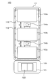
- FIG. 2 is a front view showing the internal configuration of the verification device.
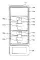
- FIG. 3 is a rear view showing the internal configuration of the verification device.
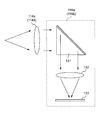
- FIG. 4 is a schematic diagram illustrating a configuration of a camera according to the embodiment.
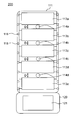
- FIG. 5 is a front view showing an internal configuration of a collation device according to another embodiment.
- the inventors of the present disclosure have focused on the following points when applying a device in which a display and a camera (imaging device) are arranged to a collation device.
- the display is at or near the front position of the user so that the user can easily see.
- the camera is also arranged at or near the front position of the user so that the user can capture an image facing the front.
- the device display or camera
- the camera is likely to be shielded by the display, so that it is difficult to obtain a front image suitable for collation.
- the display is easily shielded by the camera, so that it is difficult for the user to display characters or images in a place that is easy for the user to see.
- the image captured by the camera will also be an image in which the user's line of sight deviates from the front (since the user may see a display at a position far from the front). .
- the inventors have arrived at the idea of the configuration of the present disclosure from the above viewpoints.
- FIG. 1 shows an appearance of a collation device 100 according to an embodiment.
- FIG. 1 shows an example in which the verification device 100 is applied to a gate device provided at an airport or the like.
- the verification device 100 is placed on the table 10.
- the gate device includes a gate 11 movable to a position protruding from the table 10 and a retracted position, and a driving device (not shown), as indicated by a one-dot chain line arrow.
- the gate device drives the gate 11 by a driving device.
- the verification device 100 and the gate device can communicate with each other.
- a predetermined signal is transmitted from the collation device 100 to the driving device of the gate device.
- the driving device receives a predetermined signal
- the gate 11 is opened by moving the gate 11 to a position retracted from the table.
- the collation device 100 includes a main body 110 and a collation target image acquisition unit 120.
- the main body 110 includes a rectangular parallelepiped casing 111 that is long in the vertical direction, and a half mirror 112 that is attached to the front side of the casing 111.
- a display 113 and a camera lens 114, which will be described later, are accommodated in the housing 111.
- the collation target image acquisition unit 120 reads the passport 122 and the like placed on the glass surface 121 with a scanner (not shown) or the like provided therein. A face image as a verification target image is recorded in the passport 122 and the like. In this way, the verification target image acquisition unit 120 acquires the verification target image.
- FIG. 2 is a front view showing the internal configuration of the collation device 100.
- FIG. 2 is a view in which the half mirror 112 (FIG. 1) is removed from the casing 111 and the inside of the casing 111 is viewed from the front.
- a plurality of displays 113a, 113b, 113c are arranged with a predetermined gap D.
- camera lenses 114a and 114b are arranged in a gap D between the displays 113a, 113b, and 113c.
- three displays 113a, 113b, and 113c are arranged side by side with a gap D in the vertical direction, and two camera lenses 114a and 114b are arranged in the gap D that differs in the vertical direction.
- An LED (Light-Emitting-Diode) lamp 118 is provided on the front frame of the casing 111.
- the LED lamp 118 can irradiate light on a person (user) on the front side of the verification device 100.
- the LED lamp 118 is disposed at a position covered by the half mirror 112. Note that the LED lamp 118 may be disposed at a position not covered by the half mirror 112.
- FIG. 3 is a rear view showing the internal configuration of the verification device 100.
- FIG. 3 is a view of the inside of the housing 111 as seen from the back direction with the back plate of the housing 111 removed.
- the displays 113a, 113b, and 113c are fixed to the casing 111 by support members 115a, 115b, and 115c, respectively.
- the light incident on the camera lenses 114a and 114b enters the camera bodies 116a and 116b, respectively, and is imaged.
- the camera bodies 116a and 116b are fixed by support members 117a and 117b, respectively.
- FIG. 4 is a schematic diagram showing the configuration of the camera according to the present embodiment.
- the light that has passed through the camera lens 114a (114b) disposed in the gap D of the display is refracted in the vertical direction by the prism 131 as a polarizing member.
- the refracted light is incident on a CCD (Charge Coupled Device) 133 as an image pickup element by the imaging lens 132, converted into an electrical signal by the CCD 133, and recorded as an image.
- the light obtained by the camera lenses 114a and 114b is polarized so as to be refracted in the vertical direction by the polarizing member such as the prism 131 and then imaged by the imaging device, thereby making the space behind the displays 113b and 113c effective.
- the horizontal size of the camera main bodies 116a and 116b can be reduced, and as a result, the casing 111 of the verification device 100 can be made thinner.
- the collation apparatus 100 starts guidance by the displays 113a, 113b, and 113c.
- the collation apparatus 100 displays a character prompting the user to input a collation target image, such as “Place your passport” on the lowermost display 113c.
- a collation target image such as “Place your passport”
- the verification target image acquisition unit 120 displays the guidance on the lowermost display 113c closest to the verification target image acquisition unit 120.
- the user's line of sight can be guided in the direction of the verification target image acquisition unit 120, and the verification target image is displayed to the user.
- the position of the acquisition unit 120 can be noticed.
- the collation apparatus 100 displays characters on the bottom display 113c such as “Please turn to the front”, which prompts the user to pay attention to move his / her line of sight in a predetermined direction. Note that if the display is deleted after a certain period of time has elapsed after displaying a character that prompts the user to move his / her line of sight in a predetermined direction, the user's line of sight can be easily guided to the front.
- characters such as “Please turn to the front” are displayed on the bottom display 113c.
- the display that performs such display is not limited to the display 113c.
- a display such as “Please turn to the front” may be displayed on all the displays 113.
- the display is performed on at least a display that prompts the user to input the verification target image, there is an advantage that the user can easily notice the display. This is because the display 113c is a display on which the letters “please place your passport” are displayed, and the message “Please turn to the front” is displayed on the display. is there.
- the collation apparatus 100 displays on the displays 113a, 113b, 113c information to be communicated to the user at the time of shooting, such as a display indicating that shooting is to be performed and precautions for shooting.
- the collation apparatus 100 performs imaging using the camera lens 114a and the camera lens 114b after displaying information to be transmitted to the user during shooting or during the shooting.
- the displays 113a, 113b, and 113c which display should display information to be communicated to the user during shooting may be displayed on all displays, or may be displayed on a specific display. Also good.
- a display for displaying information may be selected based on images obtained by the camera lens 114a and the camera lens 114b. That is, when one or both of the displays adjacent to the lens that is capturing the image whose line of sight is facing the front among the images obtained by the camera lens 114a and the lens 114b are selected as the specific display, Can be reduced. Further, it may be determined based on the images obtained by the camera lens 114a and the camera lens 114b in which part of the selected display the information is displayed. For example, information can be displayed at a location facing the user on the display by detecting the angle or line of sight of the face in the image.
- a display for displaying information may be selected based on a parameter for estimating the position of the user's face, such as the height of the user. That is, when a display closer to the position of the user's face is selected as the specific display, the user's line-of-sight movement can be reduced. Further, in which part of the selected display the information is to be displayed may be determined based on a parameter for estimating the position of the user's face, such as the user's height. For example, by preparing in advance a database that associates the height of the user with the location of each display, information can be displayed at a location corresponding to the height of the user.
- the specific display is the middle display 113b among all the displays, the user's line-of-sight movement can be reduced.
- the image may be input to a classifier (identification algorithm) that has learned face images at a plurality of angles including the front face.
- a classifier identification algorithm
- it may be estimated that an image having a higher score obtained by collating the image with the image to be collated is an image facing the front.
- parameters for estimating the position of the user's face can be obtained using a distance sensor or the like arranged in the vertical direction.
- the amount of deviation can be detected even when the user is displaced from the left and right with respect to the display. Based on the amount of deviation, it may be determined where information is to be displayed on the selected display.
- the selection of whether to use the image of the camera lens 114a or the image of the camera lens 114b as the image to be used for collation may be performed by selecting the image whose line of sight is facing the front. . Similar selection may be performed by selecting an image obtained by a lens that is estimated to be closer to the face position based on a parameter that estimates the face position, such as the user's height.
- both the display and the camera lens can be arranged almost in front of the user. Therefore, even when the user visually recognizes information on the display, it is possible to capture a face image in which the line of sight is directed substantially toward the front with respect to the lens. That is, since the position where the line of sight is directed and the position where the image is captured substantially coincide, it is possible for the user to perform shooting in a state where the line of sight need not be moved. As a result, it is possible to capture a face image suitable for collation with the camera while performing easy-to-see display suitable for collation with the displays 113a, 113b, and 113c.
- both the display 113 and the camera lens 114 are arranged on the back surface of the half mirror 112 at a substantially front position of the user.
- a camera can capture a face that is almost the same as the face shown on the half mirror 112.
- the collation apparatus 100 collates these face images with an image processing unit (not shown).
- the gate 11 is opened and closed based on the result of collation.
- a plurality of displays 113a, 113b, 113c are arranged with a predetermined gap D, and camera lenses 114a, 114b are arranged in the gap D, so that the display can be viewed. Since the line of sight and the line of sight for photographing by the camera can be made substantially the same line of sight, a face image suitable for collation by the camera is displayed while displaying suitable for collation by the displays 113a, 113b, 113c to the user. Can be realized.
- the configuration of the present embodiment can be said to divide the display into a plurality of displays and arrange the camera between them. In this way, the camera can be arranged without the front position of the face being occupied only by the display.
- the case where the three displays 113a, 113b, and 113c and the two camera lenses 114a and 114b are arranged on the back side of the half mirror 112 has been described, but the number of displays and cameras is not limited thereto.
- a plurality of displays may be disposed on the back side of the half mirror, and a camera lens may be disposed in the gap D between the displays.
- five displays 113a to 113e are arranged with a gap D, and four camera lenses 114a to 114d are arranged in the gap D. This is an example.
- the direction in which the plurality of displays are arranged is not limited to the vertical direction.
- a plurality of displays may be arranged with a gap D in the horizontal direction, and a camera lens may be arranged in the gap D.
- the collation apparatus of this indication is a collation apparatus which has a plurality of displays and an imaging device, and the display is arranged with the predetermined gap D inside the case of the collation apparatus, and the imaging The lens of the apparatus is disposed in the gap D between the displays. In this way, the camera can be arranged without the front position of the face being occupied only by the display.
- a half mirror is disposed at a position covering the plurality of displays and the lenses of the imaging device.
- a plurality of the imaging devices are arranged, three or more displays are arranged in the vertical direction, and the lenses of the imaging device are arranged at different heights in the vertical direction in the gaps D between the displays. Is done.
- a plurality of imaging devices are arranged, when the user focuses his eyes on the half mirror according to the guidance of the display, there is a high possibility that the imaging device exists in front of the user. Therefore, it becomes easy to capture a face image whose line of sight is directed to the front regardless of the height of the user.
- the imaging device of the imaging device further includes a polarizing member that polarizes the light beam obtained by the lens, and the light beam polarized by the polarizing member exists on the back surface of the display. Is incident on.
- casing 111 of the collation apparatuses 100 and 200 can be made thin.
- the collation device further includes an image acquisition unit that acquires an image to be collated, and causes the image acquisition unit to read an image into a display closest to the image acquisition unit among the plurality of displays. indicate. In this way, the user can be made aware of the position of the verification target image acquisition unit 120.
- This disclosure is suitable for a collation apparatus in which a display and a camera are arranged on the back side of a half mirror.
- collation device 110 main body 111 housing 112 half mirror 113a, 113b, 113c, 113d, 113e display 114a, 114b, 114c, 114d camera lens 115a, 115b, 115c, 117a, 117b support member 116a, 116b camera main body 118 LED lamp 120 Image acquisition unit for verification 121 Glass surface
Landscapes
- Physics & Mathematics (AREA)
- Engineering & Computer Science (AREA)
- General Physics & Mathematics (AREA)
- Multimedia (AREA)
- Signal Processing (AREA)
- Theoretical Computer Science (AREA)
- Optics & Photonics (AREA)
- Human Computer Interaction (AREA)
- Spectroscopy & Molecular Physics (AREA)
- General Engineering & Computer Science (AREA)
- Image Input (AREA)
- Studio Devices (AREA)
- Cameras In General (AREA)
- Cameras Adapted For Combination With Other Photographic Or Optical Apparatuses (AREA)
- Closed-Circuit Television Systems (AREA)
- Structure And Mechanism Of Cameras (AREA)
- Indication In Cameras, And Counting Of Exposures (AREA)
Abstract
Priority Applications (4)
| Application Number | Priority Date | Filing Date | Title |
|---|---|---|---|
| US16/084,837 US10931887B2 (en) | 2016-03-17 | 2017-02-15 | Collation device |
| JP2018505359A JPWO2017159185A1 (ja) | 2016-03-17 | 2017-02-15 | 照合装置 |
| CN201780016973.6A CN108780266B (zh) | 2016-03-17 | 2017-02-15 | 对照装置 |
| EP17766192.3A EP3432065B1 (fr) | 2016-03-17 | 2017-02-15 | Dispositif de comparaison |
Applications Claiming Priority (2)
| Application Number | Priority Date | Filing Date | Title |
|---|---|---|---|
| JP2016054080 | 2016-03-17 | ||
| JP2016-054080 | 2016-03-17 |
Publications (1)
| Publication Number | Publication Date |
|---|---|
| WO2017159185A1 true WO2017159185A1 (fr) | 2017-09-21 |
Family
ID=59851399
Family Applications (1)
| Application Number | Title | Priority Date | Filing Date |
|---|---|---|---|
| PCT/JP2017/005485 Ceased WO2017159185A1 (fr) | 2016-03-17 | 2017-02-15 | Dispositif de comparaison |
Country Status (5)
| Country | Link |
|---|---|
| US (1) | US10931887B2 (fr) |
| EP (1) | EP3432065B1 (fr) |
| JP (2) | JPWO2017159185A1 (fr) |
| CN (1) | CN108780266B (fr) |
| WO (1) | WO2017159185A1 (fr) |
Cited By (3)
| Publication number | Priority date | Publication date | Assignee | Title |
|---|---|---|---|---|
| JPWO2020090972A1 (ja) * | 2018-11-01 | 2021-09-30 | 日本電気株式会社 | 顔認証装置及び顔認証装置の制御方法 |
| WO2022003853A1 (fr) * | 2020-07-01 | 2022-01-06 | 日本電気株式会社 | Dispositif de commande d'authentification, système de commande d'authentification, procédé de commande d'authentification et support non-transitoire lisible par ordinateur |
| JPWO2023021918A1 (fr) * | 2021-08-20 | 2023-02-23 |
Families Citing this family (5)
| Publication number | Priority date | Publication date | Assignee | Title |
|---|---|---|---|---|
| US10671837B2 (en) * | 2015-09-08 | 2020-06-02 | Nec Corporation | Face recognition system, face recognition method, display control apparatus, display control method, and display control program |
| JP7220373B2 (ja) | 2018-06-28 | 2023-02-10 | パナソニックIpマネジメント株式会社 | ゲート装置及びシステム |
| DE102020115566A1 (de) * | 2020-06-12 | 2021-12-16 | Bundesdruckerei Gmbh | Vorrichtung zur Erfassung biometrischer Merkmale eines Gesichts einer Person |
| DE102021117532A1 (de) * | 2021-07-07 | 2023-01-12 | Bundesdruckerei Gmbh | Vorrichtung und Verfahren zur Erzeugung eines biometrischen Bildes eines Gesichts einer Person |
| EP4607913A4 (fr) | 2022-10-21 | 2025-10-15 | Nec Corp | Dispositif de traitement d'informations, système de traitement d'informations, procédé de traitement d'informations, et support d'enregistrement |
Citations (6)
| Publication number | Priority date | Publication date | Assignee | Title |
|---|---|---|---|---|
| JP2008000464A (ja) * | 2006-06-23 | 2008-01-10 | Glory Ltd | 認証装置および認証方法 |
| WO2008066130A1 (fr) * | 2006-11-30 | 2008-06-05 | Kabushiki Kaisha Toshiba | Dispositif de contrôle d'accès, système de contrôle d'accès et procédé de contrôle d'accès |
| JP2009181371A (ja) * | 2008-01-31 | 2009-08-13 | Oki Electric Ind Co Ltd | 自動取引装置および自動取引システム |
| JP2010179012A (ja) * | 2009-02-09 | 2010-08-19 | Shiseido Co Ltd | 肌色測定装置、肌色測定プログラム、メイクアップシミュレーション装置及びメイクアップシミュレーションプログラム |
| JP2013190772A (ja) * | 2012-02-16 | 2013-09-26 | Olympus Imaging Corp | 撮像装置 |
| JP2015225627A (ja) | 2014-05-30 | 2015-12-14 | ミサワホーム株式会社 | 健康管理システム |
Family Cites Families (35)
| Publication number | Priority date | Publication date | Assignee | Title |
|---|---|---|---|---|
| GB8904535D0 (en) * | 1989-02-28 | 1989-04-12 | Barcrest Ltd | Automatic picture taking machine |
| JPH0535935A (ja) | 1991-07-26 | 1993-02-12 | Yokogawa Electric Corp | パスポートとそのパスポートを利用した出入国管理システム |
| JPH10134188A (ja) | 1996-11-01 | 1998-05-22 | Yamatake Honeywell Co Ltd | 顔画像照合装置 |
| JP2001311993A (ja) * | 2000-05-01 | 2001-11-09 | Snk Corp | フォトブース |
| JP4584483B2 (ja) | 2001-04-05 | 2010-11-24 | オリンパス株式会社 | 撮影光学系 |
| JP3819733B2 (ja) * | 2001-05-31 | 2006-09-13 | 三菱電機株式会社 | 撮像装置 |
| US20030086591A1 (en) * | 2001-11-07 | 2003-05-08 | Rudy Simon | Identity card and tracking system |
| JP4148700B2 (ja) * | 2002-05-30 | 2008-09-10 | 松下電器産業株式会社 | 目画像撮像装置 |
| JP2004147105A (ja) * | 2002-10-24 | 2004-05-20 | Oki Electric Ind Co Ltd | 遠隔対面用端末装置 |
| US7421097B2 (en) * | 2003-05-27 | 2008-09-02 | Honeywell International Inc. | Face identification verification using 3 dimensional modeling |
| JP4206903B2 (ja) | 2003-10-31 | 2009-01-14 | 沖電気工業株式会社 | チェックインシステム |
| US20050252988A1 (en) * | 2004-04-22 | 2005-11-17 | Chang Cheng H | Sprinkler having randomly swinging device |
| JP2006145645A (ja) | 2004-11-17 | 2006-06-08 | Hitachi Ltd | 情報表示装置 |
| US7924311B2 (en) * | 2004-12-21 | 2011-04-12 | Panasonic Corporation | Camera terminal and monitoring system |
| JP2007148987A (ja) * | 2005-11-30 | 2007-06-14 | Toshiba Corp | 顔認証システムおよび入退場管理システム |
| GB2447976B (en) * | 2007-03-30 | 2011-04-27 | Sony Uk Ltd | Apparatus and method of image capture |
| JP2009086801A (ja) * | 2007-09-28 | 2009-04-23 | Hitachi Omron Terminal Solutions Corp | 現金自動預入支払機 |
| JP2010062120A (ja) | 2008-08-06 | 2010-03-18 | Mitsubishi Chemicals Corp | 有機電界発光素子の隔壁用感光性組成物および有機電界発光表示装置 |
| JP2010061063A (ja) | 2008-09-08 | 2010-03-18 | Nec Computertechno Ltd | 表示制御装置、現金自動預け払い機、表示制御方法、及びプログラム |
| KR20100092222A (ko) * | 2009-02-12 | 2010-08-20 | 삼성전자주식회사 | 멀티-폴더블 모바일 디스플레이 장치 |
| CN101581874B (zh) * | 2009-03-27 | 2011-01-05 | 北京航空航天大学 | 基于多摄像机采集的远程沉浸协同工作装置 |
| CN201594274U (zh) * | 2009-07-31 | 2010-09-29 | 深圳市丰泰瑞达实业有限公司 | 一种身份识别验证系统 |
| US8581693B2 (en) * | 2010-01-22 | 2013-11-12 | Icts Europe Systems Ltd. | Passenger flow monitoring method and system |
| JP5669082B2 (ja) | 2010-04-19 | 2015-02-12 | パナソニックIpマネジメント株式会社 | 照合装置 |
| JP2012098322A (ja) | 2010-10-29 | 2012-05-24 | Sony Corp | 撮像装置 |
| TW201232425A (en) * | 2011-01-24 | 2012-08-01 | Taiwan Colour And Imaging Technology Corp | Face recognition intelligent self-service system |
| TWI545947B (zh) * | 2011-04-08 | 2016-08-11 | 南昌歐菲光電技術有限公司 | 具有影像擷取及分析模組之顯示裝置 |
| ES2469767B1 (es) * | 2011-10-28 | 2015-07-30 | Digital Centre, S.L. | Módulo de imagen para fotomatón |
| MX337444B (es) * | 2012-03-26 | 2016-03-07 | Koninkl Philips Nv | Aparatos basados en la region de brillo y metodos para la codificacion y decodificacion de imagenes de rango dinamico alto. |
| CN202662026U (zh) * | 2012-06-05 | 2013-01-09 | 上海锦江电子技术工程有限公司 | 多重人脸识别系统 |
| CN105122823A (zh) * | 2013-01-30 | 2015-12-02 | 惠普发展公司,有限责任合伙企业 | 用于多监视器显示器的控制 |
| US9269224B2 (en) * | 2013-03-11 | 2016-02-23 | Cfph, Llc | Devices for gaming |
| US9789380B2 (en) | 2013-03-25 | 2017-10-17 | Flex Booth, Inc. | System and method for tracking fitness progress from a server |
| JP2014191223A (ja) * | 2013-03-27 | 2014-10-06 | Fujitsu Ltd | 携帯端末装置、画面表示プログラム及び画面表示方法 |
| GB201410446D0 (en) * | 2014-06-12 | 2014-07-30 | Rue De Int Ltd | Secure entry system |
-
2017
- 2017-02-15 WO PCT/JP2017/005485 patent/WO2017159185A1/fr not_active Ceased
- 2017-02-15 US US16/084,837 patent/US10931887B2/en active Active
- 2017-02-15 JP JP2018505359A patent/JPWO2017159185A1/ja active Pending
- 2017-02-15 CN CN201780016973.6A patent/CN108780266B/zh active Active
- 2017-02-15 EP EP17766192.3A patent/EP3432065B1/fr active Active
-
2019
- 2019-05-17 JP JP2019093448A patent/JP6675064B2/ja active Active
Patent Citations (6)
| Publication number | Priority date | Publication date | Assignee | Title |
|---|---|---|---|---|
| JP2008000464A (ja) * | 2006-06-23 | 2008-01-10 | Glory Ltd | 認証装置および認証方法 |
| WO2008066130A1 (fr) * | 2006-11-30 | 2008-06-05 | Kabushiki Kaisha Toshiba | Dispositif de contrôle d'accès, système de contrôle d'accès et procédé de contrôle d'accès |
| JP2009181371A (ja) * | 2008-01-31 | 2009-08-13 | Oki Electric Ind Co Ltd | 自動取引装置および自動取引システム |
| JP2010179012A (ja) * | 2009-02-09 | 2010-08-19 | Shiseido Co Ltd | 肌色測定装置、肌色測定プログラム、メイクアップシミュレーション装置及びメイクアップシミュレーションプログラム |
| JP2013190772A (ja) * | 2012-02-16 | 2013-09-26 | Olympus Imaging Corp | 撮像装置 |
| JP2015225627A (ja) | 2014-05-30 | 2015-12-14 | ミサワホーム株式会社 | 健康管理システム |
Non-Patent Citations (1)
| Title |
|---|
| See also references of EP3432065A4 |
Cited By (6)
| Publication number | Priority date | Publication date | Assignee | Title |
|---|---|---|---|---|
| JPWO2020090972A1 (ja) * | 2018-11-01 | 2021-09-30 | 日本電気株式会社 | 顔認証装置及び顔認証装置の制御方法 |
| JP2022177247A (ja) * | 2018-11-01 | 2022-11-30 | 日本電気株式会社 | 顔認証装置及び顔認証装置の制御方法 |
| US12158935B2 (en) | 2018-11-01 | 2024-12-03 | Nec Corporation | Facial authentication apparatus and control method for facial authentication apparatus |
| WO2022003853A1 (fr) * | 2020-07-01 | 2022-01-06 | 日本電気株式会社 | Dispositif de commande d'authentification, système de commande d'authentification, procédé de commande d'authentification et support non-transitoire lisible par ordinateur |
| JPWO2022003853A1 (fr) * | 2020-07-01 | 2022-01-06 | ||
| JPWO2023021918A1 (fr) * | 2021-08-20 | 2023-02-23 |
Also Published As
| Publication number | Publication date |
|---|---|
| CN108780266A (zh) | 2018-11-09 |
| US20200169670A1 (en) | 2020-05-28 |
| CN108780266B (zh) | 2021-01-15 |
| JP6675064B2 (ja) | 2020-04-01 |
| JP2019149204A (ja) | 2019-09-05 |
| EP3432065B1 (fr) | 2022-05-18 |
| US10931887B2 (en) | 2021-02-23 |
| EP3432065A4 (fr) | 2019-03-27 |
| EP3432065A1 (fr) | 2019-01-23 |
| JPWO2017159185A1 (ja) | 2019-01-24 |
Similar Documents
| Publication | Publication Date | Title |
|---|---|---|
| JP6675064B2 (ja) | 照合装置 | |
| CN102986235B (zh) | 显示装置、显示方法、集成电路、程序 | |
| US8433103B2 (en) | Long distance multimodal biometric system and method | |
| KR102091055B1 (ko) | 헤드 마운트 디스플레이 | |
| JP6077655B2 (ja) | 撮影システム | |
| WO2015172514A1 (fr) | Dispositif et procédé d'acquisition d'image | |
| JP7276350B2 (ja) | 情報提供システム、情報提供方法、およびプログラム | |
| US20210192205A1 (en) | Binding of selfie face image to iris images for biometric identity enrollment | |
| JP2013182062A (ja) | 表示装置および投影装置 | |
| CN103294992A (zh) | 脸部认证传感器 | |
| CN213844157U (zh) | 生物特征采集识别系统和终端设备 | |
| JP2004205711A (ja) | 表示装置 | |
| CN105373770B (zh) | 图像采集装置、终端和图像采集方法 | |
| WO2022097721A1 (fr) | Dispositif d'acquisition de bioinformations | |
| JP2008021072A (ja) | 撮影システム、撮影装置およびそれを用いた照合装置ならびに撮影方法 | |
| JP2008246011A (ja) | 静脈認証装置 | |
| JP2017174222A (ja) | 案内出力装置、案内出力方法及びプログラム | |
| US12400481B2 (en) | Line-of-sight detection apparatus and image capturing apparatus | |
| KR102367118B1 (ko) | 디스플레이 장치 및 그의 제어 방법 | |
| KR101439983B1 (ko) | 보안 싸인 패드 및 그 보안 방법 | |
| CN120178257A (zh) | 距离测量设备、控制方法、计算机程序产品和存储介质 | |
| WO2010025529A1 (fr) | Procédé et dispositif de filmage et de reproduction d'images vidéo en 3d | |
| CN110597379A (zh) | 自动匹配乘员的电梯广告投放系统 | |
| JP2017167172A (ja) | 情報処理装置、コンテンツ評価方法、及びプログラム | |
| JP2016126378A (ja) | 認証用光学撮像装置及び認証システム |
Legal Events
| Date | Code | Title | Description |
|---|---|---|---|
| WWE | Wipo information: entry into national phase |
Ref document number: 2018505359 Country of ref document: JP |
|
| NENP | Non-entry into the national phase |
Ref country code: DE |
|
| WWE | Wipo information: entry into national phase |
Ref document number: 2017766192 Country of ref document: EP |
|
| ENP | Entry into the national phase |
Ref document number: 2017766192 Country of ref document: EP Effective date: 20181017 |
|
| 121 | Ep: the epo has been informed by wipo that ep was designated in this application |
Ref document number: 17766192 Country of ref document: EP Kind code of ref document: A1 |