WO2017159228A1 - Dispositif de prévention de chute et son procédé d'installation - Google Patents
Dispositif de prévention de chute et son procédé d'installation Download PDFInfo
- Publication number
- WO2017159228A1 WO2017159228A1 PCT/JP2017/006209 JP2017006209W WO2017159228A1 WO 2017159228 A1 WO2017159228 A1 WO 2017159228A1 JP 2017006209 W JP2017006209 W JP 2017006209W WO 2017159228 A1 WO2017159228 A1 WO 2017159228A1
- Authority
- WO
- WIPO (PCT)
- Prior art keywords
- damper
- piston
- prevention device
- furniture
- fall prevention
- Prior art date
- Legal status (The legal status is an assumption and is not a legal conclusion. Google has not performed a legal analysis and makes no representation as to the accuracy of the status listed.)
- Ceased
Links
Images


Classifications
-
- F—MECHANICAL ENGINEERING; LIGHTING; HEATING; WEAPONS; BLASTING
- F16—ENGINEERING ELEMENTS AND UNITS; GENERAL MEASURES FOR PRODUCING AND MAINTAINING EFFECTIVE FUNCTIONING OF MACHINES OR INSTALLATIONS; THERMAL INSULATION IN GENERAL
- F16F—SPRINGS; SHOCK-ABSORBERS; MEANS FOR DAMPING VIBRATION
- F16F9/00—Springs, vibration-dampers, shock-absorbers, or similarly-constructed movement-dampers using a fluid or the equivalent as damping medium
- F16F9/06—Springs, vibration-dampers, shock-absorbers, or similarly-constructed movement-dampers using a fluid or the equivalent as damping medium using both gas and liquid
-
- A—HUMAN NECESSITIES
- A47—FURNITURE; DOMESTIC ARTICLES OR APPLIANCES; COFFEE MILLS; SPICE MILLS; SUCTION CLEANERS IN GENERAL
- A47B—TABLES; DESKS; OFFICE FURNITURE; CABINETS; DRAWERS; GENERAL DETAILS OF FURNITURE
- A47B97/00—Furniture or accessories for furniture, not provided for in other groups of this subclass
-
- F—MECHANICAL ENGINEERING; LIGHTING; HEATING; WEAPONS; BLASTING
- F16—ENGINEERING ELEMENTS AND UNITS; GENERAL MEASURES FOR PRODUCING AND MAINTAINING EFFECTIVE FUNCTIONING OF MACHINES OR INSTALLATIONS; THERMAL INSULATION IN GENERAL
- F16F—SPRINGS; SHOCK-ABSORBERS; MEANS FOR DAMPING VIBRATION
- F16F15/00—Suppression of vibrations in systems; Means or arrangements for avoiding or reducing out-of-balance forces, e.g. due to motion
- F16F15/02—Suppression of vibrations of non-rotating, e.g. reciprocating systems; Suppression of vibrations of rotating systems by use of members not moving with the rotating systems
-
- F—MECHANICAL ENGINEERING; LIGHTING; HEATING; WEAPONS; BLASTING
- F16—ENGINEERING ELEMENTS AND UNITS; GENERAL MEASURES FOR PRODUCING AND MAINTAINING EFFECTIVE FUNCTIONING OF MACHINES OR INSTALLATIONS; THERMAL INSULATION IN GENERAL
- F16F—SPRINGS; SHOCK-ABSORBERS; MEANS FOR DAMPING VIBRATION
- F16F9/00—Springs, vibration-dampers, shock-absorbers, or similarly-constructed movement-dampers using a fluid or the equivalent as damping medium
- F16F9/06—Springs, vibration-dampers, shock-absorbers, or similarly-constructed movement-dampers using a fluid or the equivalent as damping medium using both gas and liquid
- F16F9/061—Mono-tubular units
-
- F—MECHANICAL ENGINEERING; LIGHTING; HEATING; WEAPONS; BLASTING
- F16—ENGINEERING ELEMENTS AND UNITS; GENERAL MEASURES FOR PRODUCING AND MAINTAINING EFFECTIVE FUNCTIONING OF MACHINES OR INSTALLATIONS; THERMAL INSULATION IN GENERAL
- F16F—SPRINGS; SHOCK-ABSORBERS; MEANS FOR DAMPING VIBRATION
- F16F9/00—Springs, vibration-dampers, shock-absorbers, or similarly-constructed movement-dampers using a fluid or the equivalent as damping medium
- F16F9/32—Details
- F16F9/48—Arrangements for providing different damping effects at different parts of the stroke
-
- F—MECHANICAL ENGINEERING; LIGHTING; HEATING; WEAPONS; BLASTING
- F16—ENGINEERING ELEMENTS AND UNITS; GENERAL MEASURES FOR PRODUCING AND MAINTAINING EFFECTIVE FUNCTIONING OF MACHINES OR INSTALLATIONS; THERMAL INSULATION IN GENERAL
- F16F—SPRINGS; SHOCK-ABSORBERS; MEANS FOR DAMPING VIBRATION
- F16F9/00—Springs, vibration-dampers, shock-absorbers, or similarly-constructed movement-dampers using a fluid or the equivalent as damping medium
- F16F9/32—Details
- F16F9/50—Special means providing automatic damping adjustment, i.e. self-adjustment of damping by particular sliding movements of a valve element, other than flexions or displacement of valve discs; Special means providing self-adjustment of spring characteristics
- F16F9/516—Special means providing automatic damping adjustment, i.e. self-adjustment of damping by particular sliding movements of a valve element, other than flexions or displacement of valve discs; Special means providing self-adjustment of spring characteristics resulting in the damping effects during contraction being different from the damping effects during extension, i.e. responsive to the direction of movement
-
- F—MECHANICAL ENGINEERING; LIGHTING; HEATING; WEAPONS; BLASTING
- F16—ENGINEERING ELEMENTS AND UNITS; GENERAL MEASURES FOR PRODUCING AND MAINTAINING EFFECTIVE FUNCTIONING OF MACHINES OR INSTALLATIONS; THERMAL INSULATION IN GENERAL
- F16F—SPRINGS; SHOCK-ABSORBERS; MEANS FOR DAMPING VIBRATION
- F16F9/00—Springs, vibration-dampers, shock-absorbers, or similarly-constructed movement-dampers using a fluid or the equivalent as damping medium
- F16F9/32—Details
- F16F9/54—Arrangements for attachment
-
- A—HUMAN NECESSITIES
- A47—FURNITURE; DOMESTIC ARTICLES OR APPLIANCES; COFFEE MILLS; SPICE MILLS; SUCTION CLEANERS IN GENERAL
- A47B—TABLES; DESKS; OFFICE FURNITURE; CABINETS; DRAWERS; GENERAL DETAILS OF FURNITURE
- A47B97/00—Furniture or accessories for furniture, not provided for in other groups of this subclass
- A47B2097/008—Anti-tip devices
-
- F—MECHANICAL ENGINEERING; LIGHTING; HEATING; WEAPONS; BLASTING
- F16—ENGINEERING ELEMENTS AND UNITS; GENERAL MEASURES FOR PRODUCING AND MAINTAINING EFFECTIVE FUNCTIONING OF MACHINES OR INSTALLATIONS; THERMAL INSULATION IN GENERAL
- F16F—SPRINGS; SHOCK-ABSORBERS; MEANS FOR DAMPING VIBRATION
- F16F2230/00—Purpose; Design features
- F16F2230/28—Inclination of a suspension element
Definitions
- the present invention relates to a fall prevention device and a mounting method thereof.
- Patent Document 1 discloses a conventional fall prevention device.
- This overturn prevention device is provided with a damper.
- the damper is attached between the upper surface of the furniture installed on the floor and the ceiling.
- a pair of base portions are connected to both ends of the damper.
- the pair of base portions pivotally support each of both end portions of the damper so as to be rotatable around a rotation axis.
- One base part contacts the upper surface of the furniture, and the other base part contacts the ceiling.
- the fall prevention device rotates the damper around the rotation axis with respect to each base portion.
- abutted to the upper surface and ceiling of furniture can be maintained. Therefore, this fall prevention apparatus can make the damping force of a damper act on furniture, can suppress the inclination of furniture, and can prevent the fall of furniture.
- the present invention has been made in view of the above-described conventional situation, and a problem to be solved is to provide a fall prevention device that can be easily attached between the upper surface of the article and the ceiling, and a method for attaching the fall prevention device. It is said.
- the fall prevention device of the present invention includes a damper.
- the damper is attached between the upper surface of the article installed on the installation surface and the ceiling.
- the damper has a cylinder and a piston.
- the cylinder is filled with a working liquid and a compressed gas (gas).
- the piston is slidably accommodated in the cylinder. And when attaching a damper between the upper surface of an article
- the piston can move into the working liquid when the article is tilted and the damper contracts a predetermined length.
- the “predetermined length” is not particularly limited. Setting this “predetermined length” small is preferable because the piston moves into the working liquid with a small contraction amount.
- the method for attaching the fall prevention device of the present invention includes a step of attaching the damper between the upper surface of the article and the ceiling. At this time, the damper is in a contracted state, and the piston is housed in a compressed gas sealed above the working liquid.
- FIG. 3 is a side view showing a state in which the damper is contracted and the piston is moved to a hydraulic oil region in the overturn prevention device of the first embodiment.
- FIG. 3 is a cross-sectional view schematically showing a main part in a state in which the damper contracts and the piston moves to a hydraulic oil region in the overturn prevention device of the first embodiment.
- Embodiment 1 that embodies the fall prevention device and the mounting method of the present invention will be described with reference to the drawings.
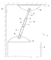
- the fall prevention device 1 of the first embodiment includes a damper 10 as shown in FIGS. 1 and 2.
- the damper 10 is attached between the upper surface of the furniture F (illustrated as an article according to the present invention) and the ceiling C.
- a pair of base portions 21 and 22 are connected to both ends of the damper 10, respectively.
- one base part 21 contacts the upper surface of the furniture F, and the other base part 22 contacts the ceiling C.
- At least one or more fall prevention devices 1 are attached between the upper surface of the furniture F and the ceiling C.
- the overturn prevention device 1 prevents the furniture F from overturning using the damping force of the damper 10 when the furniture F is tilted due to a shake such as an earthquake.
- the furniture F is installed on the floor surface with a back surface facing a wall surface W extending in the vertical direction from a floor surface (not shown) serving as an installation surface.
- the furniture F has a rectangular parallelepiped shape, and has a door, a drawer, etc. (not shown) on the front surface (the right side surface in FIG. 2), and can store clothes, accessories, and the like inside.
- the furniture F has a rectangular shape in which the horizontal cross-sectional shape is long in the left-right direction (the depth direction in FIG. 2).
- the furniture F may be tilted forward and tilted due to a shake such as an earthquake.
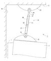
- the damper 10 has a cylinder 11 and a piston 14. Further, the damper 10 includes a rod guide 12, a rod 13, and an attenuation unit 15.
- the cylinder 11 is formed in a bottomed cylindrical shape.
- the cylinder 11 is filled with working oil (illustrated as a working liquid according to the present invention) and compressed gas.
- the rod guide 12 seals the opening of the cylinder 11.
- the rod 13 is slidably inserted into the rod guide 12, and the tip side protrudes to the outside of the cylinder 11.
- the piston 14 is slidably accommodated in the cylinder 11.
- the piston 14 is provided so as to partition the inside of the cylinder 11 into a rod side pressure chamber 11B in which the base end portion of the rod 13 is housed and an anti-rod side pressure chamber 11C.
- the base end portion of the rod 13 is connected to the piston 14.
- the attenuating portion 15 provides resistance to the flow of fluid moving between the rod side pressure chamber 11B and the anti-rod side pressure chamber 11C.
- the damping part 15 has an orifice 15A and a check valve 15B.
- the orifice 15A and the check valve 15B are respectively provided in flow paths that connect the rod-side pressure chamber 11B and the anti-rod-side pressure chamber 11C.
- Orifice 15A provides resistance to fluid flow in both directions.
- the check valve 15B allows the flow of fluid from the rod-side pressure chamber 11B to the anti-rod-side pressure chamber 11C and prevents the reverse flow.
- the orifice 15A and the check valve 15B are disposed on the piston 14 respectively.
- the damper 10 is a pressure damper in which the damping force generated during the extension operation is smaller than the damping force generated during the contraction operation.
- the extension operation of the damper 10 means an operation in which the protruding length of the rod 13 from the cylinder 11 and the length of the damper 10 become longer.
- the contraction operation of the damper 10 means an operation in which the protruding length of the rod 13 from the cylinder 11 and the length of the damper 10 become shorter.
- the expansion force of the compressed gas sealed in the cylinder 11 works in the extending direction.
- the mechanism (mechanism) in which the damping force of the damper 10 is generated by the damping unit 15 is as follows.
- the orifice 15A provides resistance to the flow of hydraulic oil between the rod-side pressure chamber 11B and the anti-rod-side pressure chamber 11C accompanying both expansion and contraction operations of the damper 10.
- the check valve 15B allows the flow of hydraulic oil from the rod-side pressure chamber 11B to the anti-rod-side pressure chamber 11C, but blocks the reverse flow. For this reason, when the damper 10 is extended, the flow path of the hydraulic oil from the rod-side pressure chamber 11B to the anti-rod-side pressure chamber 11C becomes both the orifice 15A and the check valve 15B.
- the pair of base parts 21 and 22 are a first base part 21 connected to the bottom part of the cylinder 11 and a second base part 22 connected to the tip part of the rod 13.
- the first base portion 21 contacts the upper surface of the furniture F.
- the second base portion 22 contacts the ceiling C.
- the first base portion 21 and the second base portion 22 are provided so as to be rotatable with respect to the damper 10.
- the first base portion 21 and the second base portion 22 have substantially the same form and structure.
- each joint portion 18 is formed by bending a flat metal fitting. Each joint 18 is connected to the bottom of the cylinder 11 and the tip of the rod 13. Each joint portion 18 is formed with a through hole 18 ⁇ / b> A penetrating in a direction orthogonal to the axis of the damper 10.
- the first base portion 21 and the second base portion 22 include a base portion main body 23, a bolt 24, a nut 25, and a bush 26 that are rotating shaft members, respectively. .
- the first base portion 21 and the second base portion 22 have substantially the same form and structure, the first base portion 21 will be described as an example in the following description.
- the base part main body 23 is a cavity.
- the base portion main body 23 has an insertion hole 23A.
- the rotating shaft member is inserted into the insertion hole 23A.
- the rotating shaft member includes a bolt 24 inserted from one insertion hole 23 ⁇ / b> A of the base portion main body 23 and a nut 25 screwed into the shaft portion 24 ⁇ / b> A of the bolt 24.
- the central axis of the bolt 24 becomes the rotation axis of the damper 10 in each of the base portions 21 and 22.
- the bush 26 has a substantially cylindrical shape as shown in FIG.
- the bush 26 is an elastic body.
- the length of the bush 26 is such that when the base 26 is attached to the base portion main body 23, a slight gap is generated between the both end faces and the base portion main body 23.
- the bush 26 is formed with a recess 26 ⁇ / b> A that goes around the outer peripheral surface of the central portion.
- the outer diameter of the recess 26 ⁇ / b> A is substantially equal to the inner diameter of the through hole 18 ⁇ / b> A formed in the joint portion 18 of the damper 10.
- the outer diameter of the portion of the bush 26 rising from both ends of the recess 26 ⁇ / b> A is larger than the inner diameter of the through hole 18 ⁇ / b> A formed in the joint portion 18 of the damper 10. Further, the outer peripheral surface 26B of both ends of the bush 26 is reduced in diameter outward. Therefore, the bush 26 is inserted into the through hole 18A formed in the joint portion 18 of the damper 10 while being elastically deformed. The bush 26 is attached to the joint portion 18 of the damper 10 with the recess 26A fitted in the through hole 18A.
- the inner diameter of the bush 26 is slightly larger than the outer diameter of the shaft 24A of the bolt 24.
- the inner peripheral surface 26C of both ends of the bush 26 is expanded in the outward direction.
- the bush 26 is rotatable around the shaft portion 24 ⁇ / b> A of the bolt 24.
- the bush 26 can be inclined with respect to the shaft portion 24A of the bolt 24 in a range in which the inner peripheral surfaces 26C of both end portions whose diameters have been expanded come into contact with the outer peripheral surface of the shaft portion 24A of the bolt 24. That is, the damper 10 having the bush 26 attached to the joint portion 18 is rotatable around the shaft portion 24A of the bolt 24 and is swingable in a direction crossing the rotation direction. Further, the elastic deformation of the bush 26 allows the damper 10 to swing more greatly in the direction crossing the rotational direction.
- the piston 14 of the fall prevention device 1 When the damper 10 is mounted between the upper surface of the furniture F and the ceiling C, the piston 14 of the fall prevention device 1 is accommodated in a compressed gas sealed above the hydraulic oil. That is, when the overturn prevention device 1 is attached, the piston 14 is located in the compressed gas region 16 in the cylinder 11 as shown in FIGS. In addition, when the furniture F is tilted and the damper 10 is contracted by the predetermined length s, the fall prevention device 1 moves the piston 14 into the hydraulic oil. In other words, when the furniture F is tilted and the damper 10 is contracted by the predetermined length s due to the shaking of the earthquake or the like, the fall prevention device 1 causes the piston 14 to move into the compressed gas region 16 in the cylinder 11 as shown in FIGS. To the hydraulic oil region 17.
- the fall prevention device 1 having such a configuration is attached between the upper surface of the furniture F and the ceiling C as follows.
- the damper 10 is contracted.
- the piston 14 is housed in a compressed gas sealed above the hydraulic oil.
- the damper 10 is attached between the upper surface of the furniture F and the ceiling C.
- the first base portion 21 connected to the lower end portion of the damper 10 is placed in contact with the upper surface of the furniture F.
- the damper 10 is mounted so as to have an inclination angle of 15 ° to 20 ° with respect to the vertical direction.
- the damper 10 is extended while maintaining the inclination angle of the damper 10, and the second base portion 22 is brought into contact with the ceiling C.
- the positions of the base portions 21 and 22 are adjusted so that the rotation direction of the damper 10 and the direction in which the furniture F tilts are substantially parallel.
- the piston 14 does not move into the hydraulic oil region 17 but slides only within the compressed gas region 16. For this reason, the damper 10 can be contracted with a load smaller than the state in which the piston is housed in the hydraulic oil.
- the damper 10 extends, and a force that stretches between the upper surface of the furniture F and the ceiling C acts. Thereby, the angle of the adjusted damper 10 and the position of each base part 21 and 22 are suitably hold
- the overturn prevention device 1 is attached so that the piston 14 moves from the compressed gas region 16 to the hydraulic oil region 17 when the damper 10 contracts by a predetermined length s.
- the damper 10 contracts to a predetermined length s or more due to the swing of the furniture F due to an earthquake or the like
- the piston 14 in the cylinder 11 moves from the compressed gas region 16 to the hydraulic oil region 17.
- the damping force by hydraulic fluid arises. For this reason, the shaking of the furniture F is effectively attenuated.
- the fall prevention device 1 causes the piston 14 in the cylinder 11 to slide only in the compressed gas region 16. To do.
- the overturn prevention device 1 of the first embodiment includes the damper 10.
- the damper 10 is attached between the upper surface of the furniture F installed on the installation surface and the ceiling C.
- the damper 10 has a cylinder 11 and a piston 14.
- the cylinder 11 is filled with hydraulic oil and compressed gas.
- the piston 14 is slidably accommodated in the cylinder 11. And when attaching the damper 10 between the upper surface of the furniture F and the ceiling C, the piston 14 is accommodated in the compressed gas enclosed above hydraulic oil.
- a piston 14 is slidably accommodated in a cylinder 11 filled with hydraulic oil and compressed gas.
- the hydraulic oil is sealed below the compressed gas.
- the piston 14 is accommodated in compressed gas.
- the fall prevention device 1 of the first embodiment can be easily attached between the upper surface of the furniture F and the ceiling.
- the piston 14 moves into the hydraulic oil when the furniture F is tilted and the damper 10 is contracted by a predetermined length.
- the piston 14 is housed in the compressed gas until the damper 10 is contracted by the predetermined length s.
- the piston 14 is stored in the hydraulic oil. Thereby, a damping force is generated by the hydraulic oil.
- the inclination of the furniture F is suitably suppressed, and a fall can be prevented.
- the method of attaching the overturn prevention device 1 of Embodiment 1 includes a step of attaching the damper 10 between the upper surface of the furniture F and the ceiling C. At this time, the damper 10 is in a contracted state and the piston 14 is housed in the compressed gas. That is, the damper 10 is attached in a state where the piston 14 is not in the hydraulic oil. When such a damper 10 is brought into a contracted state, no drag force is generated by the hydraulic oil. For this reason, the damper 10 can be contracted with a smaller force than the state in which the piston 14 is housed in the hydraulic oil.
- the method for attaching the fall prevention device 1 of Embodiment 1 can easily attach the fall prevention device 1 between the upper surface of the furniture F and the ceiling C.
- the fall prevention device is attached to furniture, but the present invention is not limited to this.
- a bed in which a plurality of beds are connected in the vertical direction a large TV, a refrigerator, a bookcase, a show You may attach to other articles
- the fall prevention device is attached to the furniture placed on the floor with the back face facing the wall, but the furniture placed on the floor without being adjacent to the wall. Etc. may be attached.
- the pressure damper is used.
- the present invention is not limited to this.
- a double-effect damper or an extension damper may be used. When these are used, it is necessary to attach the base part appropriately according to the type of the damper, such as fixing the base part to the article or the ceiling, paying attention to the attachment position and the number of attachments, the inclination angle and the inclination direction of the damper.
- the damper is extended by the expansion force of the compressed gas.
- the present invention is not limited to this.
- the biasing force is further applied by other means such as a compression coil spring or a combination thereof.
- the damper may be extended.
- the working oil is employed as the working liquid sealed in the cylinder.
- the present invention is not limited to this, and other liquid may be employed as long as it generates a predetermined damping force. .
Landscapes
- Engineering & Computer Science (AREA)
- General Engineering & Computer Science (AREA)
- Mechanical Engineering (AREA)
- Physics & Mathematics (AREA)
- Acoustics & Sound (AREA)
- Aviation & Aerospace Engineering (AREA)
- Vibration Prevention Devices (AREA)
- Fluid-Damping Devices (AREA)
Abstract
L'invention concerne : un dispositif de prévention de chute pouvant être facilement installé entre la surface supérieure d'un article et un plafond ; et un procédé d'installation du dispositif de prévention de chute. Un dispositif de prévention de chute (1) est pourvu d'un amortisseur (10). L'amortisseur (10) est installé entre la surface supérieure d'un meuble (F) (article) installé sur une surface d'installation et un plafond (C). L'amortisseur (10) comporte un cylindre (11) et un piston (14). De l'huile hydraulique (liquide d'actionnement) et du gaz comprimé sont enfermés hermétiquement à l'intérieur du cylindre (11). Le piston (14) est logé de manière coulissante à l'intérieur du cylindre (11). Pendant l'installation de l'amortisseur (10) entre la surface supérieure du meuble (F) et le plafond (C), le piston (14) est situé dans le gaz comprimé enfermé hermétiquement au-dessus de l'huile hydraulique. Le piston (14) peut se déplacer dans l'huile hydraulique lorsque le meuble (F) bascule pour rétracter l'amortisseur (10) d'une longueur prédéterminée.
Priority Applications (2)
| Application Number | Priority Date | Filing Date | Title |
|---|---|---|---|
| CN201780005237.0A CN108778059A (zh) | 2016-03-15 | 2017-02-20 | 翻倒防止装置及其安装方法 |
| US16/069,306 US20190017564A1 (en) | 2016-03-15 | 2017-02-20 | Overturn preventing device and method of mounting the same |
Applications Claiming Priority (2)
| Application Number | Priority Date | Filing Date | Title |
|---|---|---|---|
| JP2016050410A JP6205445B2 (ja) | 2016-03-15 | 2016-03-15 | 転倒防止装置、及びその取り付け方法 |
| JP2016-050410 | 2016-03-15 |
Publications (1)
| Publication Number | Publication Date |
|---|---|
| WO2017159228A1 true WO2017159228A1 (fr) | 2017-09-21 |
Family
ID=59851240
Family Applications (1)
| Application Number | Title | Priority Date | Filing Date |
|---|---|---|---|
| PCT/JP2017/006209 Ceased WO2017159228A1 (fr) | 2016-03-15 | 2017-02-20 | Dispositif de prévention de chute et son procédé d'installation |
Country Status (5)
| Country | Link |
|---|---|
| US (1) | US20190017564A1 (fr) |
| JP (1) | JP6205445B2 (fr) |
| CN (1) | CN108778059A (fr) |
| TW (1) | TW201738476A (fr) |
| WO (1) | WO2017159228A1 (fr) |
Families Citing this family (2)
| Publication number | Priority date | Publication date | Assignee | Title |
|---|---|---|---|---|
| TWI844804B (zh) * | 2021-10-29 | 2024-06-11 | 台鍛工業股份有限公司 | 繫結裝置 |
| US20250261756A1 (en) * | 2024-02-19 | 2025-08-21 | Mirza Faizan | Stabilizer system for controlling tipping of furniture |
Citations (7)
| Publication number | Priority date | Publication date | Assignee | Title |
|---|---|---|---|---|
| JPS6041906A (ja) * | 1983-08-17 | 1985-03-05 | 松浦 祐 | 家具類の転倒防止装置 |
| JP2578169B2 (ja) * | 1988-06-15 | 1997-02-05 | 松下電工株式会社 | 床下収納庫の蓋体の開閉構造 |
| JP3101569U (ja) * | 2003-11-10 | 2004-06-17 | 株式会社ブィ・シー・イー・ジャパン | 蓋跳ね上げ式金庫 |
| US20060027954A1 (en) * | 2004-08-06 | 2006-02-09 | Nesbitt Thomas R | Independent and integrated compact air-bump stops |
| WO2016021487A1 (fr) * | 2014-08-06 | 2016-02-11 | Kyb株式会社 | Dispositif anti-basculement |
| JP5864068B1 (ja) * | 2014-08-28 | 2016-02-17 | Kyb株式会社 | 転倒防止装置 |
| WO2016031515A1 (fr) * | 2014-08-28 | 2016-03-03 | Kyb株式会社 | Dispositif anti-basculement et procédé d'installation associé |
Family Cites Families (10)
| Publication number | Priority date | Publication date | Assignee | Title |
|---|---|---|---|---|
| US1142825A (en) * | 1914-01-09 | 1915-06-15 | William F Lyons | Shock-absorber. |
| US2760603A (en) * | 1951-01-19 | 1956-08-28 | Ferrarotti Giuseppe | Shock absorber with rubber valve |
| US2959410A (en) * | 1958-10-27 | 1960-11-08 | Jarry Hydraulics | Double stage oleo-pneumatic shock absorber |
| US3304076A (en) * | 1964-12-31 | 1967-02-14 | Letourneau Westinghouse Compan | Suspension unit |
| US3304077A (en) * | 1964-12-31 | 1967-02-14 | Letourneau Westinghouse Compan | Suspension unit |
| US4484732A (en) * | 1982-06-01 | 1984-11-27 | Gould Larry D | Constant and variable force tensioning devices utilizing atmospheric pressure |
| US5083756A (en) * | 1990-07-24 | 1992-01-28 | Jaromir Tobias | Load support vibration isolation mount |
| US7963509B2 (en) * | 2007-01-31 | 2011-06-21 | Fox Factory, Inc. | Travel control for a gas spring and gas spring having very short travel modes |
| JP6212337B2 (ja) * | 2013-09-13 | 2017-10-11 | Kyb株式会社 | 単筒型液圧緩衝器 |
| EP2913460B1 (fr) * | 2014-02-19 | 2017-08-23 | Chihiro Sangyo Co., Ltd. | Amortisseur pour un bâtiment |
-
2016
- 2016-03-15 JP JP2016050410A patent/JP6205445B2/ja not_active Expired - Fee Related
-
2017
- 2017-02-20 US US16/069,306 patent/US20190017564A1/en not_active Abandoned
- 2017-02-20 WO PCT/JP2017/006209 patent/WO2017159228A1/fr not_active Ceased
- 2017-02-20 CN CN201780005237.0A patent/CN108778059A/zh not_active Withdrawn
- 2017-03-08 TW TW106107536A patent/TW201738476A/zh unknown
Patent Citations (7)
| Publication number | Priority date | Publication date | Assignee | Title |
|---|---|---|---|---|
| JPS6041906A (ja) * | 1983-08-17 | 1985-03-05 | 松浦 祐 | 家具類の転倒防止装置 |
| JP2578169B2 (ja) * | 1988-06-15 | 1997-02-05 | 松下電工株式会社 | 床下収納庫の蓋体の開閉構造 |
| JP3101569U (ja) * | 2003-11-10 | 2004-06-17 | 株式会社ブィ・シー・イー・ジャパン | 蓋跳ね上げ式金庫 |
| US20060027954A1 (en) * | 2004-08-06 | 2006-02-09 | Nesbitt Thomas R | Independent and integrated compact air-bump stops |
| WO2016021487A1 (fr) * | 2014-08-06 | 2016-02-11 | Kyb株式会社 | Dispositif anti-basculement |
| JP5864068B1 (ja) * | 2014-08-28 | 2016-02-17 | Kyb株式会社 | 転倒防止装置 |
| WO2016031515A1 (fr) * | 2014-08-28 | 2016-03-03 | Kyb株式会社 | Dispositif anti-basculement et procédé d'installation associé |
Also Published As
| Publication number | Publication date |
|---|---|
| US20190017564A1 (en) | 2019-01-17 |
| TW201738476A (zh) | 2017-11-01 |
| JP6205445B2 (ja) | 2017-09-27 |
| CN108778059A (zh) | 2018-11-09 |
| JP2017164074A (ja) | 2017-09-21 |
Similar Documents
| Publication | Publication Date | Title |
|---|---|---|
| JP5864067B1 (ja) | 転倒防止装置及びその取付方法 | |
| JP6353867B2 (ja) | 転倒防止装置 | |
| WO2017163701A1 (fr) | Dispositif de prévention de chute et procédé de montage de celui-ci | |
| JP6674286B2 (ja) | 転倒防止装置 | |
| JP6205445B2 (ja) | 転倒防止装置、及びその取り付け方法 | |
| JP6722468B2 (ja) | ダンパ及びこのダンパを備えた転倒防止装置 | |
| JP6397256B2 (ja) | 転倒防止装置及びそれを備えた物品 | |
| WO2017169295A1 (fr) | Amortisseur et dispositif anti-chute pourvu dudit amortisseur | |
| JP6386087B2 (ja) | 制振棚 | |
| WO2017212701A1 (fr) | Support et dispositif de prévention de chute | |
| JP6397272B2 (ja) | 転倒防止装置 | |
| JP6255458B1 (ja) | 転倒防止装置 | |
| JP2017169853A (ja) | 転倒防止装置 | |
| TW201727098A (zh) | 防傾倒裝置 | |
| JP2017169854A (ja) | 連結部材及び転倒防止装置 | |
| JP2017176218A (ja) | 転倒防止装置 | |
| JP2017225539A (ja) | 転倒防止装置 | |
| JP2016036444A (ja) | 転倒防止装置及び転倒防止装置付き物品 | |
| JP2016063992A (ja) | 転倒防止装置用取付け具及び転倒防止装置 |
Legal Events
| Date | Code | Title | Description |
|---|---|---|---|
| NENP | Non-entry into the national phase |
Ref country code: DE |
|
| 121 | Ep: the epo has been informed by wipo that ep was designated in this application |
Ref document number: 17766235 Country of ref document: EP Kind code of ref document: A1 |
|
| 122 | Ep: pct application non-entry in european phase |
Ref document number: 17766235 Country of ref document: EP Kind code of ref document: A1 |