WO2017163411A1 - Dispositif d'actionnement - Google Patents
Dispositif d'actionnement Download PDFInfo
- Publication number
- WO2017163411A1 WO2017163411A1 PCT/JP2016/059680 JP2016059680W WO2017163411A1 WO 2017163411 A1 WO2017163411 A1 WO 2017163411A1 JP 2016059680 W JP2016059680 W JP 2016059680W WO 2017163411 A1 WO2017163411 A1 WO 2017163411A1
- Authority
- WO
- WIPO (PCT)
- Prior art keywords
- coil
- iron core
- winding
- operating device
- movable iron
- Prior art date
- Legal status (The legal status is an assumption and is not a legal conclusion. Google has not performed a legal analysis and makes no representation as to the accuracy of the status listed.)
- Ceased
Links
Images


Classifications
-
- H—ELECTRICITY
- H01—ELECTRIC ELEMENTS
- H01H—ELECTRIC SWITCHES; RELAYS; SELECTORS; EMERGENCY PROTECTIVE DEVICES
- H01H50/00—Details of electromagnetic relays
- H01H50/44—Magnetic coils or windings
-
- H—ELECTRICITY
- H01—ELECTRIC ELEMENTS
- H01H—ELECTRIC SWITCHES; RELAYS; SELECTORS; EMERGENCY PROTECTIVE DEVICES
- H01H3/00—Mechanisms for operating contacts
- H01H3/22—Power arrangements internal to the switch for operating the driving mechanism
- H01H3/28—Power arrangements internal to the switch for operating the driving mechanism using electromagnet
-
- H—ELECTRICITY
- H01—ELECTRIC ELEMENTS
- H01H—ELECTRIC SWITCHES; RELAYS; SELECTORS; EMERGENCY PROTECTIVE DEVICES
- H01H50/00—Details of electromagnetic relays
- H01H50/16—Magnetic circuit arrangements
- H01H50/18—Movable parts of magnetic circuits, e.g. armature
-
- H—ELECTRICITY
- H01—ELECTRIC ELEMENTS
- H01H—ELECTRIC SWITCHES; RELAYS; SELECTORS; EMERGENCY PROTECTIVE DEVICES
- H01H50/00—Details of electromagnetic relays
- H01H50/16—Magnetic circuit arrangements
- H01H50/36—Stationary parts of magnetic circuit, e.g. yoke
-
- H—ELECTRICITY
- H02—GENERATION; CONVERSION OR DISTRIBUTION OF ELECTRIC POWER
- H02B—BOARDS, SUBSTATIONS OR SWITCHING ARRANGEMENTS FOR THE SUPPLY OR DISTRIBUTION OF ELECTRIC POWER
- H02B13/00—Arrangement of switchgear in which switches are enclosed in, or structurally associated with, a casing, e.g. cubicle
- H02B13/02—Arrangement of switchgear in which switches are enclosed in, or structurally associated with, a casing, e.g. cubicle with metal casing
- H02B13/035—Gas-insulated switchgear
-
- H—ELECTRICITY
- H01—ELECTRIC ELEMENTS
- H01H—ELECTRIC SWITCHES; RELAYS; SELECTORS; EMERGENCY PROTECTIVE DEVICES
- H01H50/00—Details of electromagnetic relays
- H01H50/64—Driving arrangements between movable part of magnetic circuit and contact
- H01H50/641—Driving arrangements between movable part of magnetic circuit and contact intermediate part performing a rectilinear movement
Definitions
- the present invention relates to an operating device for operating a movable iron core with a magnetic flux generated in a coil.
- Patent Document 1 discloses an operating device provided with double coils.
- the inner coil is energized when the movable iron core is operated, and a small current is allowed to flow through the outer coil for a long time to serve as a holding coil.
- the generated magnetic flux differs between when the inner coil is energized and when the outer coil is energized. Therefore, even if it is attempted to operate the movable iron core by energizing the outer coil, the operation speed is different from the operation speed of the movable iron core when the inner coil is energized.
- the movable iron core is operated in the same way, even if there is an abnormality in the energization system to one coil. It is difficult to improve the reliability of the operating device by operating the movable iron core by energizing the other coil.
- the present invention has been made in view of the above, and it is possible to operate a movable iron core at the same speed even when any coil of multiple coils is energized.
- An object of the present invention is to obtain an operating device capable of improving the reliability of the apparatus.
- the present invention provides a movable iron core that can be reciprocated along an operation axis, a fixed iron core that is provided on the operation axis and faces the movable iron core, and an operation
- a first coil composed of a first winding wound in a cylindrical shape centered on an axis, and a second coil wound around the outside of the first coil in a cylindrical shape centered on an operating axis
- the 2nd coil comprised by these.
- the wire diameter of the second winding is larger than the wire diameter of the first winding.
- the operating device According to the operating device according to the present invention, it is possible to operate the movable iron core at the same speed regardless of which of the multiple coils is energized, thereby improving the reliability of the product. There is an effect that can be achieved.
- Sectional drawing of the operating device concerning Embodiment 1 of this invention Plan view of electromagnet in Embodiment 1 Side view of electromagnet in Embodiment 1 Cross-sectional view along the line AA shown in FIG. Sectional drawing of the electromagnet with which the operating device concerning the modification of Embodiment 1 is provided. Sectional drawing of the electromagnet with which the operating device concerning Embodiment 2 of this invention is provided. Sectional drawing of the electromagnet with which the operating device concerning Embodiment 3 of this invention is provided.
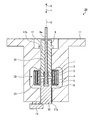
- FIG. 1 is a cross-sectional view of the operating device according to the first embodiment of the present invention.
- the operating device 20 includes a yoke 11 having a hole 17 formed along the operation axis C. Inside the hole 17 of the yoke 11, the fixed iron core 9 and the movable iron core 10 are provided to face each other.
- the movable iron core 10 is provided on the end 17a side of the hole 17 and the fixed iron core 9 is provided on the other end 17b side.
- the fixed iron core 9 is fixed inside the hole 17.
- the movable iron core 10 is movable along the operation axis C inside the hole 17.
- the yoke 11 is provided with a stopper 14 that closes one end 17a of the hole 17 and prevents the movable iron core 10 from falling off.
- an urging portion 13 that applies an urging force in a direction in which the fixed iron core 9 and the movable iron core 10 are separated from each other.
- the biasing portion 13 is, for example, a coil spring.
- a gap is formed between the fixed iron core 9 and the movable iron core 10 by the urging force of the urging portion 13.
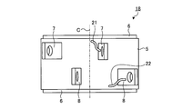
- FIG. 2 is a plan view of the electromagnet 18 in the first embodiment.
- FIG. 3 is a side view of the electromagnet 18 in the first embodiment.
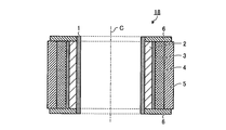
- 4 is a cross-sectional view taken along line AA shown in FIG. 2 to 4 also show the operation axis C of the controller device 20.
- the first coil 2 is provided outside the winding frame 1, and the insulator 3 is provided outside thereof.
- the first coil 2 is formed by winding the conductive first winding 21 shown in FIG.
- the second coil 4 is provided outside the insulator 3.
- the second coil 4 is formed by winding the conductive second winding 22 shown in FIG. 3 around the insulator 3.
- the first coil 2 and the second coil 4 have the same number of turns of the windings 21 and 22, that is, the number of turns of the windings 21 and 22.
- the concept of “the number of turns is the same” in this specification includes a case where there is a slight difference between the number of turns of the first winding 21 and the number of turns of the second winding 22. .
- the wire diameter of the second winding 22 is larger than the wire diameter of the first winding 21.
- the tape 5 is wound around the outside of the second coil 4.
- a first coil terminal 7 and a second coil terminal 8 are fixed to the outside of the tape 5.
- Both end surfaces of the electromagnet 18 in an annular shape are covered with a plate-like end plate 6.
- the end of the first winding 21 is drawn outside from between the insulator 3, the second coil 4, the tape 5, and the end plate 6, and as shown in FIG. It is connected to the.
- the end of the second winding 22 is drawn outward from between the tape 5 and the end plate 6 and connected to the second coil terminal 8 as shown in FIG.
- a power supply line (not shown) is connected to each of the first coil terminal 7 and the second coil terminal 8.
- the first coil terminal 7 and the second coil terminal 8 can be separately energized through a power line. Accordingly, the first coil 2 and the second coil 4 can be energized separately.
- the center position of the electromagnet 18 and the position of the gap between the fixed iron core 9 and the movable iron core 10 coincide with each other. More specifically, in the direction along the operation axis C, the center position of the first coil 2, the center position of the second coil 4, and the position of the gap between the fixed iron core 9 and the movable iron core 10 match. To do.
- a plunger 12 is fixed to a surface of the movable iron core 10 that faces the fixed iron core 9.
- the plunger 12 has a rod shape extending along the operation axis C.
- the fixed iron core 9 is formed with a through hole 9a extending along the operation axis C.
- the plunger 12 passes through the through hole 9 a and protrudes toward the other end 17 b of the hole 17 of the yoke 11.
- an attractive force can be generated between the fixed iron core 9 and the movable iron core 10 by generating a magnetic flux by energizing the first coil 2 or the second coil 4. .
- the movable iron core 10 moves toward the fixed iron core 9 against the urging force of the urging portion 13.
- the plunger 12 fixed to the movable iron core 9 moves in the direction indicated by the arrow X.
- the attractive force between the fixed iron core 9 and the movable iron core 10 disappears.
- the operation lever can be operated by energizing or stopping the first coil 2 or the second coil 4. Become.
- the number of turns of the windings 21 and 22 is the same, and the distance from the operation axis C is greater in the second coil 4 than in the first coil 2.
- the total length of the second winding 22 is longer than the total length of the first winding 21.
- the electrical resistance per unit length is greater than that of the first winding 21.
- the second winding 22 is smaller.
- the total length of the second winding 22 in the second coil 4 is longer than the total length of the first winding 21 in the first coil 2.
- the difference between the electrical resistance of the entire first winding 21 and the resistance of the entire second winding 22 of the second coil 4 is made smaller than when the windings 21 and 22 have the same wire diameter. be able to.
- the generated magnetic flux can be made identical between when the first coil 2 is energized and when the second coil 4 is energized. Therefore, the same suction force generated between the fixed iron core 9 and the movable iron core 10 can be achieved when the first coil 2 is energized and when the second coil 4 is energized. That is, the operating speed of the movable iron core 10 can be made identical between when the first coil 2 is energized and when the second coil 4 is energized.
- the plunger 12 when the plunger 12 is connected to the operation lever of the gas insulated switchgear, it is possible to equalize the time until the operation is completed when the first coil 2 or the second coil 4 is energized.
- the coil that is normally energized is the first coil 2
- the second coil 4 is a backup coil when the first coil 2 cannot be energized.
- the movable iron core 10 can be operated at a speed. As described above, in the operating device 20 according to the first embodiment, the movable iron core 10 can be operated at the same speed regardless of which coil is energized, and the reliability of the product can be improved. it can.
- the center position of the first coil 2, the center position of the second coil 4, and the position of the gap between the fixed iron core 9 and the movable iron core 10 coincide with each other in the direction along the operation axis C.
- the gap between the fixed iron core 9 and the movable iron core 10 can be located in a region where the magnetic flux density is high. Thereby, the attraction force generated by the magnetic flux generated from the first coil 2 or the second coil 4 is maximized.
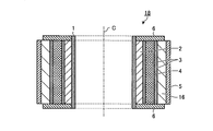
- FIG. 5 is a cross-sectional view of the electromagnet 18 provided in the operating device according to the modification of the first embodiment.
- a third coil 16 is provided outside the second coil 4.
- the wire diameter of the third winding (not shown) wound as the third coil 16 is set to the second winding.
- the operating speed of the movable iron core 10 is the same when the first coil 2 is energized, when the second coil 4 is energized, and when the third coil 16 is energized. Can be achieved. Further, since the number of backup coils is increased, the reliability of the product can be further improved.
- the number of coils is not limited to three shown as a modification, and may be four or more. That is, the reliability of the product can be further improved by providing multiple coils around the operation axis C and increasing the wire diameter of the winding wound around the outer coil.
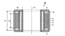
- FIG. FIG. 6 is a cross-sectional view of an electromagnet provided in the operating device according to the second embodiment of the present invention.
- symbol is attached
- the length h ⁇ b> 2 of the second coil 4 is shorter than the length h ⁇ b> 1 of the first coil 2 in the direction along the operation axis C. More specifically, the relationship 1 ⁇ h1 / h2 ⁇ 1.3 is satisfied.
- An insulator 15 is provided in the gap between the end plate 6 and the second coil 4. In the direction along the operation axis C, the center position of the first coil 2 and the center position of the second coil 4 are matched.
- the electromagnet 38 can be reduced in size. As the electromagnet 38 is downsized, the operating device can be downsized.
- FIG. 7 is a cross-sectional view of the electromagnet provided in the operating device according to the third embodiment of the present invention.
- symbol is attached
- the length h1 of the first coil 2 is shorter than the length h2 of the second coil 4 in the direction along the operation axis C. More specifically, the relationship of 0.7 ⁇ h1 / h2 ⁇ 1 is satisfied.
- An insulator 15 is provided in the gap between the end plate 6 and the first coil 2. In the direction along the operation axis C, the center position of the first coil 2 and the center position of the second coil 4 are matched.
- the configuration described in the above embodiment shows an example of the contents of the present invention, and can be combined with another known technique, and can be combined with other configurations without departing from the gist of the present invention. It is also possible to omit or change the part.
Landscapes
- Physics & Mathematics (AREA)
- Electromagnetism (AREA)
- Engineering & Computer Science (AREA)
- Power Engineering (AREA)
- Electromagnets (AREA)
- Gas-Insulated Switchgears (AREA)
Abstract
L'invention concerne un dispositif d'actionnement (20) qui est équipé de : un noyau mobile (10) qui peut être déplacé vers l'avant et vers l'arrière le long d'un axe d'actionnement (C) ; un noyau immobile (9) qui est disposé sur l'axe d'actionnement (C) et est tourné vers le noyau mobile (10) ; une première bobine (2) qui est constituée d'un premier bobinage enroulé selon une forme cylindrique autour de l'axe d'actionnement (C) ; et une seconde bobine (4) qui est constituée d'un second bobinage enroulé selon une forme cylindrique autour de l'axe d'actionnement (C) sur l'extérieur de la première bobine (2). En outre, le diamètre de fil du second bobinage est plus grand que celui du premier bobinage.
Priority Applications (3)
| Application Number | Priority Date | Filing Date | Title |
|---|---|---|---|
| US16/079,505 US20190051480A1 (en) | 2016-03-25 | 2016-03-25 | Operating device |
| JP2016558162A JP6104478B1 (ja) | 2016-03-25 | 2016-03-25 | 操作装置 |
| PCT/JP2016/059680 WO2017163411A1 (fr) | 2016-03-25 | 2016-03-25 | Dispositif d'actionnement |
Applications Claiming Priority (1)
| Application Number | Priority Date | Filing Date | Title |
|---|---|---|---|
| PCT/JP2016/059680 WO2017163411A1 (fr) | 2016-03-25 | 2016-03-25 | Dispositif d'actionnement |
Publications (1)
| Publication Number | Publication Date |
|---|---|
| WO2017163411A1 true WO2017163411A1 (fr) | 2017-09-28 |
Family
ID=59366076
Family Applications (1)
| Application Number | Title | Priority Date | Filing Date |
|---|---|---|---|
| PCT/JP2016/059680 Ceased WO2017163411A1 (fr) | 2016-03-25 | 2016-03-25 | Dispositif d'actionnement |
Country Status (3)
| Country | Link |
|---|---|
| US (1) | US20190051480A1 (fr) |
| JP (1) | JP6104478B1 (fr) |
| WO (1) | WO2017163411A1 (fr) |
Families Citing this family (1)
| Publication number | Priority date | Publication date | Assignee | Title |
|---|---|---|---|---|
| CN114824727B (zh) * | 2022-04-21 | 2023-03-24 | 燕山大学 | 六棱台式折展单元及其组成的折展机构 |
Citations (6)
| Publication number | Priority date | Publication date | Assignee | Title |
|---|---|---|---|---|
| JPH0357203A (ja) * | 1989-07-25 | 1991-03-12 | Matsushita Electric Works Ltd | 電磁石装置及び電磁開閉器 |
| JPH073809Y2 (ja) * | 1984-09-08 | 1995-01-30 | 株式会社東芝 | 回転電機ステ−タの口出線接続装置 |
| JP2006108041A (ja) * | 2004-10-08 | 2006-04-20 | Matsushita Electric Works Ltd | 電磁開閉装置 |
| JP2008010167A (ja) * | 2006-06-27 | 2008-01-17 | Matsushita Electric Works Ltd | 電磁開閉装置 |
| WO2012176505A1 (fr) * | 2011-06-20 | 2012-12-27 | 日産自動車株式会社 | Relais électromagnétique |
| JP2013089516A (ja) * | 2011-10-20 | 2013-05-13 | Mitsubishi Electric Corp | 電磁操作装置 |
Family Cites Families (8)
| Publication number | Priority date | Publication date | Assignee | Title |
|---|---|---|---|---|
| DE1279182B (de) * | 1965-09-11 | 1968-10-03 | Siemens Ag | Supraleitungsspule |
| JP4569547B2 (ja) * | 2006-02-23 | 2010-10-27 | 株式会社デンソー | 電磁スイッチ |
| DE102007014764A1 (de) * | 2007-03-28 | 2008-06-12 | Robert Bosch Gmbh | Einrückrelais für Starter |
| JP5488238B2 (ja) * | 2010-06-17 | 2014-05-14 | 日産自動車株式会社 | 電磁リレー |
| JP5445435B2 (ja) * | 2010-12-08 | 2014-03-19 | 三菱電機株式会社 | 電磁操作式真空遮断器 |
| US9324486B2 (en) * | 2013-06-17 | 2016-04-26 | Massachusetts Institute Of Technology | Partial insulation superconducting magnet |
| JP6300157B2 (ja) * | 2013-08-02 | 2018-03-28 | パナソニックIpマネジメント株式会社 | 電磁継電器 |
| CN204067247U (zh) * | 2014-06-26 | 2014-12-31 | 德昌电机(深圳)有限公司 | 起动器及其电磁开关 |
-
2016
- 2016-03-25 US US16/079,505 patent/US20190051480A1/en not_active Abandoned
- 2016-03-25 WO PCT/JP2016/059680 patent/WO2017163411A1/fr not_active Ceased
- 2016-03-25 JP JP2016558162A patent/JP6104478B1/ja active Active
Patent Citations (6)
| Publication number | Priority date | Publication date | Assignee | Title |
|---|---|---|---|---|
| JPH073809Y2 (ja) * | 1984-09-08 | 1995-01-30 | 株式会社東芝 | 回転電機ステ−タの口出線接続装置 |
| JPH0357203A (ja) * | 1989-07-25 | 1991-03-12 | Matsushita Electric Works Ltd | 電磁石装置及び電磁開閉器 |
| JP2006108041A (ja) * | 2004-10-08 | 2006-04-20 | Matsushita Electric Works Ltd | 電磁開閉装置 |
| JP2008010167A (ja) * | 2006-06-27 | 2008-01-17 | Matsushita Electric Works Ltd | 電磁開閉装置 |
| WO2012176505A1 (fr) * | 2011-06-20 | 2012-12-27 | 日産自動車株式会社 | Relais électromagnétique |
| JP2013089516A (ja) * | 2011-10-20 | 2013-05-13 | Mitsubishi Electric Corp | 電磁操作装置 |
Also Published As
| Publication number | Publication date |
|---|---|
| JPWO2017163411A1 (ja) | 2018-04-12 |
| US20190051480A1 (en) | 2019-02-14 |
| JP6104478B1 (ja) | 2017-03-29 |
Similar Documents
| Publication | Publication Date | Title |
|---|---|---|
| JP5205008B2 (ja) | 扁平型電磁アクチュエータ | |
| JP2004088992A (ja) | ボイスコイル型リニアアクチュエータ及びこのアクチュエータを用いた装置、並びにこのアクチュエータの製造方法 | |
| JP2008237004A5 (fr) | ||
| CN106716565B (zh) | 电磁的调整设备 | |
| EP3425648B1 (fr) | Solénoïde | |
| US20200227189A1 (en) | Electromagnet and a method for the production thereof | |
| JP5965451B2 (ja) | 高速ソレノイド | |
| JP6642485B2 (ja) | 電磁継電器 | |
| JP2012244901A5 (fr) | ||
| JP2016143623A (ja) | 電磁継電器 | |
| JP6104478B1 (ja) | 操作装置 | |
| US7420300B2 (en) | Voice coil motor | |
| EP3642855B1 (fr) | Système électromagnétique | |
| CN101136577A (zh) | 电动机及线圈的绕线方法 | |
| JP6554492B2 (ja) | ソレノイド | |
| JP5627475B2 (ja) | 開閉器の操作機構 | |
| JP5659625B2 (ja) | ソレノイド装置 | |
| KR101552573B1 (ko) | 고속 솔레노이드 | |
| JP2012019613A (ja) | リニアモータ | |
| JP5884777B2 (ja) | リニアソレノイド | |
| JP5696403B2 (ja) | リニアアクチュエータ | |
| JP2008166392A (ja) | 電磁アクチュエータおよび開閉器 | |
| JP2018142501A (ja) | 電磁継電器 | |
| JP2018142502A (ja) | 電磁継電器 | |
| JP6367144B2 (ja) | シリンダロッド装置 |
Legal Events
| Date | Code | Title | Description |
|---|---|---|---|
| ENP | Entry into the national phase |
Ref document number: 2016558162 Country of ref document: JP Kind code of ref document: A |
|
| NENP | Non-entry into the national phase |
Ref country code: DE |
|
| 121 | Ep: the epo has been informed by wipo that ep was designated in this application |
Ref document number: 16895442 Country of ref document: EP Kind code of ref document: A1 |
|
| 122 | Ep: pct application non-entry in european phase |
Ref document number: 16895442 Country of ref document: EP Kind code of ref document: A1 |