WO2017163684A1 - Dispositif de direction assistée électrique et procédé de commande de dispositif de direction assistée électrique - Google Patents
Dispositif de direction assistée électrique et procédé de commande de dispositif de direction assistée électrique Download PDFInfo
- Publication number
- WO2017163684A1 WO2017163684A1 PCT/JP2017/005736 JP2017005736W WO2017163684A1 WO 2017163684 A1 WO2017163684 A1 WO 2017163684A1 JP 2017005736 W JP2017005736 W JP 2017005736W WO 2017163684 A1 WO2017163684 A1 WO 2017163684A1
- Authority
- WO
- WIPO (PCT)
- Prior art keywords
- insertion hole
- electric power
- power steering
- bearing
- plug
- Prior art date
- Legal status (The legal status is an assumption and is not a legal conclusion. Google has not performed a legal analysis and makes no representation as to the accuracy of the status listed.)
- Ceased
Links
Images

Classifications
-
- F—MECHANICAL ENGINEERING; LIGHTING; HEATING; WEAPONS; BLASTING
- F16—ENGINEERING ELEMENTS AND UNITS; GENERAL MEASURES FOR PRODUCING AND MAINTAINING EFFECTIVE FUNCTIONING OF MACHINES OR INSTALLATIONS; THERMAL INSULATION IN GENERAL
- F16C—SHAFTS; FLEXIBLE SHAFTS; ELEMENTS OR CRANKSHAFT MECHANISMS; ROTARY BODIES OTHER THAN GEARING ELEMENTS; BEARINGS
- F16C19/00—Bearings with rolling contact, for exclusively rotary movement
- F16C19/02—Bearings with rolling contact, for exclusively rotary movement with bearing balls essentially of the same size in one or more circular rows
- F16C19/04—Bearings with rolling contact, for exclusively rotary movement with bearing balls essentially of the same size in one or more circular rows for radial load mainly
- F16C19/06—Bearings with rolling contact, for exclusively rotary movement with bearing balls essentially of the same size in one or more circular rows for radial load mainly with a single row or balls
-
- B—PERFORMING OPERATIONS; TRANSPORTING
- B62—LAND VEHICLES FOR TRAVELLING OTHERWISE THAN ON RAILS
- B62D—MOTOR VEHICLES; TRAILERS
- B62D5/00—Power-assisted or power-driven steering
- B62D5/04—Power-assisted or power-driven steering electrical, e.g. using an electric servo-motor connected to, or forming part of, the steering gear
- B62D5/0442—Conversion of rotational into longitudinal movement
- B62D5/0454—Worm gears
-
- B—PERFORMING OPERATIONS; TRANSPORTING
- B62—LAND VEHICLES FOR TRAVELLING OTHERWISE THAN ON RAILS
- B62D—MOTOR VEHICLES; TRAILERS
- B62D3/00—Steering gears
- B62D3/02—Steering gears mechanical
- B62D3/04—Steering gears mechanical of worm type
-
- B—PERFORMING OPERATIONS; TRANSPORTING
- B62—LAND VEHICLES FOR TRAVELLING OTHERWISE THAN ON RAILS
- B62D—MOTOR VEHICLES; TRAILERS
- B62D5/00—Power-assisted or power-driven steering
- B62D5/04—Power-assisted or power-driven steering electrical, e.g. using an electric servo-motor connected to, or forming part of, the steering gear
-
- B—PERFORMING OPERATIONS; TRANSPORTING
- B62—LAND VEHICLES FOR TRAVELLING OTHERWISE THAN ON RAILS
- B62D—MOTOR VEHICLES; TRAILERS
- B62D5/00—Power-assisted or power-driven steering
- B62D5/04—Power-assisted or power-driven steering electrical, e.g. using an electric servo-motor connected to, or forming part of, the steering gear
- B62D5/0403—Power-assisted or power-driven steering electrical, e.g. using an electric servo-motor connected to, or forming part of, the steering gear characterised by constructional features, e.g. common housing for motor and gear box
-
- B—PERFORMING OPERATIONS; TRANSPORTING
- B62—LAND VEHICLES FOR TRAVELLING OTHERWISE THAN ON RAILS
- B62D—MOTOR VEHICLES; TRAILERS
- B62D5/00—Power-assisted or power-driven steering
- B62D5/04—Power-assisted or power-driven steering electrical, e.g. using an electric servo-motor connected to, or forming part of, the steering gear
- B62D5/0409—Electric motor acting on the steering column
-
- F—MECHANICAL ENGINEERING; LIGHTING; HEATING; WEAPONS; BLASTING
- F16—ENGINEERING ELEMENTS AND UNITS; GENERAL MEASURES FOR PRODUCING AND MAINTAINING EFFECTIVE FUNCTIONING OF MACHINES OR INSTALLATIONS; THERMAL INSULATION IN GENERAL
- F16C—SHAFTS; FLEXIBLE SHAFTS; ELEMENTS OR CRANKSHAFT MECHANISMS; ROTARY BODIES OTHER THAN GEARING ELEMENTS; BEARINGS
- F16C35/00—Rigid support of bearing units; Housings, e.g. caps, covers
- F16C35/04—Rigid support of bearing units; Housings, e.g. caps, covers in the case of ball or roller bearings
- F16C35/06—Mounting or dismounting of ball or roller bearings; Fixing them onto shaft or in housing
- F16C35/067—Fixing them in a housing
-
- F—MECHANICAL ENGINEERING; LIGHTING; HEATING; WEAPONS; BLASTING
- F16—ENGINEERING ELEMENTS AND UNITS; GENERAL MEASURES FOR PRODUCING AND MAINTAINING EFFECTIVE FUNCTIONING OF MACHINES OR INSTALLATIONS; THERMAL INSULATION IN GENERAL
- F16C—SHAFTS; FLEXIBLE SHAFTS; ELEMENTS OR CRANKSHAFT MECHANISMS; ROTARY BODIES OTHER THAN GEARING ELEMENTS; BEARINGS
- F16C35/00—Rigid support of bearing units; Housings, e.g. caps, covers
- F16C35/04—Rigid support of bearing units; Housings, e.g. caps, covers in the case of ball or roller bearings
- F16C35/06—Mounting or dismounting of ball or roller bearings; Fixing them onto shaft or in housing
- F16C35/07—Fixing them on the shaft or housing with interposition of an element
- F16C35/077—Fixing them on the shaft or housing with interposition of an element between housing and outer race ring
-
- F—MECHANICAL ENGINEERING; LIGHTING; HEATING; WEAPONS; BLASTING
- F16—ENGINEERING ELEMENTS AND UNITS; GENERAL MEASURES FOR PRODUCING AND MAINTAINING EFFECTIVE FUNCTIONING OF MACHINES OR INSTALLATIONS; THERMAL INSULATION IN GENERAL
- F16H—GEARING
- F16H1/00—Toothed gearings for conveying rotary motion
- F16H1/02—Toothed gearings for conveying rotary motion without gears having orbital motion
- F16H1/04—Toothed gearings for conveying rotary motion without gears having orbital motion involving only two intermeshing members
- F16H1/12—Toothed gearings for conveying rotary motion without gears having orbital motion involving only two intermeshing members with non-parallel axes
- F16H1/16—Toothed gearings for conveying rotary motion without gears having orbital motion involving only two intermeshing members with non-parallel axes comprising worm and worm-wheel
-
- F—MECHANICAL ENGINEERING; LIGHTING; HEATING; WEAPONS; BLASTING
- F16—ENGINEERING ELEMENTS AND UNITS; GENERAL MEASURES FOR PRODUCING AND MAINTAINING EFFECTIVE FUNCTIONING OF MACHINES OR INSTALLATIONS; THERMAL INSULATION IN GENERAL
- F16H—GEARING
- F16H1/00—Toothed gearings for conveying rotary motion
- F16H1/02—Toothed gearings for conveying rotary motion without gears having orbital motion
- F16H1/04—Toothed gearings for conveying rotary motion without gears having orbital motion involving only two intermeshing members
- F16H1/12—Toothed gearings for conveying rotary motion without gears having orbital motion involving only two intermeshing members with non-parallel axes
- F16H1/16—Toothed gearings for conveying rotary motion without gears having orbital motion involving only two intermeshing members with non-parallel axes comprising worm and worm-wheel
- F16H1/166—Toothed gearings for conveying rotary motion without gears having orbital motion involving only two intermeshing members with non-parallel axes comprising worm and worm-wheel with members rotating around axes on the worm or worm-wheel
-
- F—MECHANICAL ENGINEERING; LIGHTING; HEATING; WEAPONS; BLASTING
- F16—ENGINEERING ELEMENTS AND UNITS; GENERAL MEASURES FOR PRODUCING AND MAINTAINING EFFECTIVE FUNCTIONING OF MACHINES OR INSTALLATIONS; THERMAL INSULATION IN GENERAL
- F16H—GEARING
- F16H55/00—Elements with teeth or friction surfaces for conveying motion; Worms, pulleys or sheaves for gearing mechanisms
- F16H55/02—Toothed members; Worms
- F16H55/22—Toothed members; Worms for transmissions with crossing shafts, especially worms, worm-gears
- F16H55/24—Special devices for taking up backlash
-
- F—MECHANICAL ENGINEERING; LIGHTING; HEATING; WEAPONS; BLASTING
- F16—ENGINEERING ELEMENTS AND UNITS; GENERAL MEASURES FOR PRODUCING AND MAINTAINING EFFECTIVE FUNCTIONING OF MACHINES OR INSTALLATIONS; THERMAL INSULATION IN GENERAL
- F16H—GEARING
- F16H57/00—General details of gearing
- F16H57/02—Gearboxes; Mounting gearing therein
- F16H57/021—Shaft support structures, e.g. partition walls, bearing eyes, casing walls or covers with bearings
-
- F—MECHANICAL ENGINEERING; LIGHTING; HEATING; WEAPONS; BLASTING
- F16—ENGINEERING ELEMENTS AND UNITS; GENERAL MEASURES FOR PRODUCING AND MAINTAINING EFFECTIVE FUNCTIONING OF MACHINES OR INSTALLATIONS; THERMAL INSULATION IN GENERAL
- F16C—SHAFTS; FLEXIBLE SHAFTS; ELEMENTS OR CRANKSHAFT MECHANISMS; ROTARY BODIES OTHER THAN GEARING ELEMENTS; BEARINGS
- F16C2361/00—Apparatus or articles in engineering in general
- F16C2361/61—Toothed gear systems, e.g. support of pinion shafts
-
- F—MECHANICAL ENGINEERING; LIGHTING; HEATING; WEAPONS; BLASTING
- F16—ENGINEERING ELEMENTS AND UNITS; GENERAL MEASURES FOR PRODUCING AND MAINTAINING EFFECTIVE FUNCTIONING OF MACHINES OR INSTALLATIONS; THERMAL INSULATION IN GENERAL
- F16H—GEARING
- F16H57/00—General details of gearing
- F16H57/02—Gearboxes; Mounting gearing therein
- F16H57/021—Shaft support structures, e.g. partition walls, bearing eyes, casing walls or covers with bearings
- F16H2057/0213—Support of worm gear shafts
Definitions
- the present invention relates to an electric power steering apparatus and a method for manufacturing the electric power steering apparatus.
- JP2012-197029A discloses an electric power steering device in which a spring is compressed between the outer peripheral surface of the bearing and the plug by press-fitting the plug into a through hole formed in the gear case. Has been.
- An O-ring is interposed between the outer peripheral surface of the gear case and the head of the plug. The gap between the gear case and the plug is sealed by the O-ring, and the gear case is sealed.
- an O-ring is provided between the plug and the gear case, and the number of parts is large. Further, before the plug is press-fitted into the through hole of the gear case, an O-ring must be assembled to the plug. Therefore, it takes time to manufacture the power steering device.
- An object of the present invention is to make it possible to reduce the number of parts of an electric power steering device while preventing mixing of shavings into a gear case.
- an electric power steering device includes a worm shaft that rotates as the electric motor is driven, a worm shaft that meshes with the worm shaft and transmits the rotational force of the electric motor to a rack shaft that steers the wheel.
- a wheel, a bearing that rotatably supports the worm shaft, a biasing member that biases the worm shaft toward the worm wheel via the bearing, a worm shaft and the bearing are accommodated, and the biasing member can be inserted.
- a gear case having an insertion hole; and a closing member that closes the insertion hole.
- the closing member is disposed in the insertion hole and is in contact with the inner peripheral surface of the insertion hole, and is continuous with the body portion toward the bearing.
- a support portion that supports the biasing member, and the outer peripheral surface of the closing member is formed in a curved shape from the main body portion to the support portion.
- the present invention also provides an urging member for urging the worm shaft toward the worm wheel via a bearing, a case that houses the worm shaft and the bearing, and has an insertion hole through which the urging member can be inserted, A closing member that closes the hole, and the closing member is disposed in the insertion hole and is in contact with the inner peripheral surface of the insertion hole, and is formed continuously from the body portion toward the bearing to support the biasing member.
- a method for manufacturing an electric power steering apparatus includes a step of press-fitting a closing member into an insertion hole in a state where a protruding portion protruding from a bottom portion is supported.
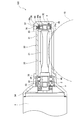
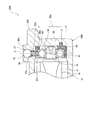
- FIG. 1 is a cross-sectional view showing an electric power steering apparatus according to a first embodiment of the present invention.
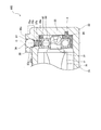
- FIG. 2 is an enlarged cross-sectional view showing the periphery of the closing member in FIG.
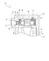
- FIG. 3 is an enlarged cross-sectional view corresponding to FIG. 2 showing an electric power steering apparatus according to a modification of the first embodiment.
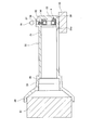
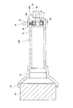
- FIG. 4 is a view for explaining the method for manufacturing the electric power steering apparatus according to the first embodiment.
- FIG. 5 is a cross-sectional view showing an electric power steering apparatus according to the second embodiment of the present invention.
- 6 is an enlarged cross-sectional view showing the periphery of the closing member in FIG.
- FIG. 7 is a diagram for explaining a method of manufacturing the electric power steering apparatus according to the second embodiment.
- an electric power steering apparatus 100 according to a first embodiment of the present invention will be described with reference to FIGS. 1 to 4.
- the electric power steering device 100 is mounted on a vehicle and assists the steering force applied by the driver to the steering wheel.
- the electric power steering apparatus 100 includes a worm shaft 20 connected to the output shaft of the electric motor 1 and a worm wheel 10 that meshes with the worm shaft 20.
- the worm shaft 20 rotates as the electric motor 1 is driven.
- the worm wheel 10 rotates as the worm shaft 20 rotates, and transmits the rotational force of the electric motor 1 to the rack shaft that steers the wheel.
- the rotation of the worm shaft 20 is decelerated and transmitted to the worm wheel 10.
- the worm wheel 10 and the worm shaft 20 constitute a worm speed reducer.
- the steering shaft (not shown) includes an input shaft connected to the steering handle, an output shaft connected to the rack shaft, and a torsion bar connecting the input shaft and the output shaft.
- the worm wheel 10 is provided on the output shaft of the steering shaft.
- the torsion bar is twisted by the relative rotation between the input shaft and the output shaft.
- the electric motor 1 outputs a torque corresponding to the steering torque calculated based on the torsion amount of the torsion bar.
- the torque output from the electric motor 1 is transmitted from the worm shaft 20 to the worm wheel 10 and applied as an assist torque to the output shaft of the steering shaft.
- the worm shaft 20 is accommodated in a gear case 30 made of aluminum.
- the gear case 30 is formed in a bag shape.
- the gear case 30 includes a cylindrical portion 31 that surrounds the worm shaft 20 around the axis of the worm shaft 20, and a bottom portion 32 that closes one open end of the cylindrical portion 31.
- the cylindrical part 31 and the bottom part 32 are integrally formed. Since liquid does not flow into the cylindrical portion 31 from between the cylindrical portion 31 and the bottom portion 32, the bag-shaped gear case 30 is sealed with a lid member separate from the cylindrical portion 31 in the opening of the cylindrical portion 31. Excellent waterproofing compared to the stopped structure.
- the gear case 30 further includes a first large diameter portion 33 having an inner diameter larger than the inner diameter of the cylindrical portion 31 and a second large diameter portion 34 having an inner diameter larger than the inner diameter of the first large diameter portion 33.
- the first large diameter portion 33 is formed continuously from the other opening end of the cylindrical portion 31, and the second large diameter portion 34 is formed continuously from the first large diameter portion 33.
- the electric motor 1 is attached to the second large diameter portion 34.
- the cylindrical part 31 of the gear case 30 has a wheel hole 31a through which a part of the worm wheel 10 can be inserted.
- the wheel hole 31 a extends between the outer peripheral surface and the inner peripheral surface of the cylindrical portion 31 and extends in the axial direction of the worm shaft 20.
- a tooth portion 21 that meshes with a tooth portion (not shown) of the worm wheel 10 is formed on a part of the worm shaft 20.
- the tooth portion 21 of the worm shaft 20 and the tooth portion of the worm wheel 10 mesh with each other through the wheel hole 31a.
- Both end portions 22 and 23 of the worm shaft 20 are rotatably supported by a first bearing 40 and a second bearing 50, respectively.
- the end portion 22 located on the electric motor 1 side with respect to the tooth portion 21 is also referred to as a “base end portion 22”
- the end portion 23 located on the opposite side of the tooth portion 21 from the electric motor 1 is referred to as “ Also referred to as “tip portion 23”.
- the first bearing 40 supports the base end portion 22 and the second bearing 50 supports the distal end portion 23.
- Each of the first and second bearings 40 and 50 is a bearing including an annular inner ring, an annular outer ring, and a ball disposed between the inner ring and the outer ring.
- the outer ring of the first bearing 40 is fixed to the inner peripheral surface of the first large diameter portion 33 of the gear case 30. Specifically, a step portion 35 is formed on the inner peripheral surface of the gear case 30, and the lock nut 2 is fastened in the first large diameter portion 33. The outer ring of the first bearing 40 is sandwiched between the step portion 35 and the lock nut 2.
- the inner ring of the first bearing 40 is fixed to the outer peripheral surface of the base end portion 22 of the worm shaft 20. Specifically, a step portion 24 is formed on the outer peripheral surface of the worm shaft 20, and the joint 3 is press-fitted into the worm shaft 20. The inner ring of the first bearing 40 is sandwiched between the step portion 24 and the joint 3.
- the second bearing 50 is accommodated in the holder 4.
- the holder 4 is disposed in a bearing housing portion 36 formed on the bottom portion 32 side of the cylindrical portion 31.
- the inner peripheral surface 36a of the bearing accommodating portion 36 is formed in a circular shape.
- the second bearing 50 is urged by a coil spring 60 as an urging member so that the gap between the tooth portion 21 of the worm shaft 20 and the tooth portion of the worm wheel 10 is reduced. That is, the electric power steering apparatus 100 includes the coil spring 60 that urges the worm shaft 20 toward the worm wheel 10 via the second bearing 50.
- An insertion hole 37 through which the coil spring 60 can be inserted is formed in the vicinity of the bottom 32 in the cylindrical portion 31.
- the insertion hole 37 is formed in a hole forming portion 38 that protrudes from the outer peripheral surface of the cylindrical portion 31 in the radial direction of the worm shaft 20.
- the insertion hole 37 penetrates between the outer surface 38 a of the hole forming portion 38 and the inner peripheral surface 36 a of the bearing housing portion 36.
- the central axis of the insertion hole 37 substantially coincides with the radial direction of the worm shaft 20.
- the insertion hole 37 is sealed with a steel plug 70 as a closing member.
- the coil spring 60 is compressed between the plug 70 and the second bearing 50. Therefore, the coil spring 60 exhibits a restoring force, and this restoring force acts on the second bearing 50 as a biasing force that biases the worm shaft 20 toward the worm wheel 10.
- the inner peripheral surface of the holder 4 is formed in a long hole shape so that the second bearing 50 can move in the biasing direction of the coil spring 60.
- a pair of plane portions facing each other are formed on the inner peripheral surface of the holder 4.
- the pair of flat portions extend in the biasing direction of the coil spring 60. Further, the distance between the pair of flat portions is slightly larger than the outer diameter of the second bearing 50. Therefore, the movement of the second bearing 50 is not restricted by the inner peripheral surface of the holder 4, and the second bearing 50 can move in the holder 4 in the biasing direction of the coil spring 60.
- the second bearing 50 may not be accommodated in the holder 4.
- the second bearing 50 may be directly accommodated in the bearing accommodating portion 36 as long as it can move in the biasing direction of the coil spring 60.
- the teeth 21 of the worm shaft 20 and the teeth of the worm wheel 10 are worn. Since the second bearing 50 is biased by the coil spring 60, the second bearing 50 moves in the holder 4 according to the wear amount of the tooth portion 21 of the worm shaft 20 and the tooth portion of the worm wheel 10. Therefore, backlash at the tooth portion 21 of the worm shaft 20 and the tooth portion of the worm wheel 10 is reduced.
- FIG. 2 is an enlarged cross-sectional view showing the periphery of the plug 70.
- the plug 70 is formed in a spherical shape.
- the outer diameter of the plug 70 is larger than the coil diameter of the coil spring 60.
- the insertion hole 37 has an outer hole portion 37 a that opens to the outer surface 38 a of the hole forming portion 38, and an inner hole portion 37 b that opens to the inner peripheral surface 36 a of the bearing housing portion 36.
- the inner diameter of the inner hole portion 37b is smaller than the inner diameter of the outer hole portion 37a, and the inner hole portion 37b and the outer hole portion 37a are continuously formed coaxially. That is, the central axis C of the insertion hole 37 coincides with the central axis of the outer hole part 37a and coincides with the central axis of the inner hole part 37b.
- a step portion 37d is formed between the outer hole portion 37a and the inner hole portion 37b.
- the outer hole 37a is formed so that the plug 70 can be press-fitted.
- the outer hole portion 37a has an inner diameter that is slightly smaller than the outer diameter of the plug 70 in a state before the plug 70 is press-fitted.
- the inner hole portion 37b has an inner diameter that is smaller than the outer diameter of the plug 70, and is formed so that the plug 70 cannot be press-fitted.
- the outer surface 38a of the hole forming portion 38 is formed in a flat shape.
- the plug 70 is disposed in the outer hole portion 37a so that the tangent plane on the surface of the plug 70 forms the same plane as the outer surface 38a.
- a gap is formed between the step portion 37d and the plug 70. Since the plug 70 does not contact the stepped portion 37d, the plug 70 may be pressed into the outer hole portion 37a until the tangential plane of the plug 70 forms the same plane as the outer surface 38a of the hole forming portion 38. Management becomes easy.
- the coil spring 60 is disposed through the inner hole 37b.
- the inner diameter of the inner hole portion 37 b is slightly larger than the coil diameter of the coil spring 60. Therefore, the inner hole portion 37 b prevents the coil spring 60 from bending without restricting expansion and contraction of the coil spring 60.
- the central portion 70a of the plug 70 in the central axis direction of the insertion hole 37 is in contact with the inner peripheral surface of the outer hole portion 37a. Therefore, no gap is formed between the outer peripheral surface of the central portion 70a and the outer hole portion 37a, and the gear case 30 is sealed.
- the lower part 70b of the plug 70 located on the coil spring 60 side with respect to the central part 70a supports the coil spring 60. Since the plug 70 closes the insertion hole 37 and supports the coil spring 60, it is not necessary to provide a member for supporting the coil spring 60 in the electric power steering apparatus 100 separately from the plug 70. Therefore, the number of parts of the electric power steering apparatus 100 can be reduced.
- the surface of the lower portion 70 b of the plug 70 is formed in a spherical shape, when the coil spring 60 is supported by the plug 70 by press-fitting the plug 70 into the outer hole portion 37 a, the axis of the coil spring 60 is aligned with the insertion hole 37.
- the coil spring 60 moves so as to coincide with the central axis C. Therefore, the coil spring 60 can be easily disposed at a desired position.
- the plug 70 Since the plug 70 has a spherical shape, no corner is formed on the plug 70. Therefore, when the plug 70 is press-fitted into the outer hole portion 37 a of the insertion hole 37, the outer peripheral surface of the plug 70 and the inner peripheral surface of the outer hole portion 37 a are difficult to be cut. Therefore, mixing of shavings into the gear case 30 can be prevented while increasing the outer diameter of the plug 70.
- the inner peripheral surface of the outer hole 37a can be deformed to fit the outer peripheral surface of the plug 70 as the plug 70 is press-fitted. Therefore, when the plug 70 is press-fitted, no gap is formed between the inner peripheral surface of the outer hole portion 37 a and the outer peripheral surface of the plug 70, and the insertion hole 37 is closed by the plug 70. Therefore, since it is not necessary to provide a seal member between the inner peripheral surface of the outer hole 37a and the outer peripheral surface of the plug 70, the number of parts of the electric power steering device 100 can be reduced.
- the plug 70 or the outer hole portion 37a is sealed when the electric power steering device 100 is manufactured (assembled).
- the process of assembling the members is not necessary. Therefore, the manufacturing time of the electric power steering apparatus 100 can be shortened.
- the electric power steering apparatus 100 it is possible to reduce the number of parts and the manufacturing time while preventing the mixing of shavings into the gear case 30.
- the plug 70 is made of steel, and the hole forming portion 38 is made of aluminum. Since the hardness of steel is higher than that of aluminum, the plug 70 is not easily chipped when the plug 70 is press-fitted into the outer hole 37a, and between the outer peripheral surface of the plug 70 and the inner peripheral surface of the outer hole 37a. Wear is unlikely to occur. Therefore, it is possible to more reliably prevent the generation of shavings when the plug 70 is press-fitted into the outer hole portion 37a.
- the electric power steering apparatus 100 is not limited to a form in which the plug 70 is made of steel and the hole forming portion 38 is made of aluminum. If the hardness of the plug 70 is higher than the hardness of the inner peripheral wall of the insertion hole 37, the generation of shavings can be prevented.
- Spherical members are used in many devices, and technology for producing spherical members has been established.
- the plug 70 is formed in a spherical shape, the plug 70 can be manufactured more easily.
- FIG. 3 is an enlarged cross-sectional view showing an electric power steering apparatus 101 according to a modification of the first embodiment corresponding to FIG.
- the electric power steering apparatus 101 includes a non-spherical plug 71 as a closing member instead of the spherical plug 70.
- the plug 71 has a main body portion 71 a disposed in the outer hole portion 37 a and a support portion 71 b that supports the coil spring 60.
- the main body 71a is formed in a columnar shape and is in contact with the inner peripheral surface of the outer hole 37a.
- the support portion 71 b is formed continuously with the main body portion 71 a toward the second bearing 50.
- the outer peripheral surface of the plug 71 is formed in a curved shape inward of the insertion hole 37 from the main body portion 71a to the support portion 71b. In other words, there is no corner at the boundary between the main body 71a and the support 71b. Since the boundary portion between the main body portion 71a and the support portion 71b has a curved shape, the outer peripheral surface of the plug 71 and the inner peripheral surface of the outer hole portion 37a are difficult to be scraped when the plug 71 is press-fitted. Therefore, similarly to the spherical plug 70 (see FIGS. 1 and 2), it is possible to reduce the number of parts and the manufacturing time while preventing mixing of shavings into the gear case 30.
- the closing member is not limited to a spherical shape.
- the blocking member only needs to have a main body portion disposed in the insertion hole 37 and a support portion that supports the coil spring 60. And the outer peripheral surface of a closure member should just be formed in the curved surface form from the main-body part to the support part.
- the central portion 70a corresponds to the main body portion
- the lower portion 70b corresponds to the support portion.
- the second bearing 50 is accommodated in the holder 4 and the holder 4 is accommodated in the bearing accommodating portion 36.
- the coil spring 60 is inserted into the insertion hole 37.
- the gear case 30 is supported using the support tools 81 and 82.
- the support member 81 is fitted into the second large diameter portion 34, and the tubular portion 31 is placed on the support member 82.
- the tubular portion 31 is placed on the support member 82 so that the hole forming portion 38 is located on the opposite side of the support member 82 with respect to the central axis of the tubular portion 31.
- the plug 70 is press-fitted into the outer hole 37 a of the insertion hole 37, and the coil spring 60 is compressed between the second bearing 50 and the plug 70. Since the hole forming portion 38 is located on the side opposite to the support tool 82, the plug 70 is press-fitted toward the support tool 82. Therefore, the cylindrical part 31 is reliably supported and the plug 70 can be easily press-fitted into the outer hole part 37a.
- the inner peripheral surface of the outer hole portion 37a is deformed to fit the outer peripheral surface of the plug 70 when the plug 70 is press-fitted. Therefore, no gap is formed between the inner peripheral surface of the outer hole portion 37 a and the outer peripheral surface of the plug 70, and the insertion hole 37 can be closed only by the plug 70.
- the support 81 is extracted from the second large diameter portion 34.
- the worm shaft 20 is inserted into the gear case 30, and the distal end portion 23 of the worm shaft 20 is inserted into the second bearing 50.
- the assembly of the electric motor 1 and the worm wheel 10 to the gear case 30 is omitted here.
- the outer peripheral surface of the plug 70 is formed in a curved shape from the central portion 70a to the lower portion 70b, the outer peripheral surface of the plug 70 and the inner peripheral surface of the outer hole portion 37a are scraped when the plug 70 is press-fitted. hard. Therefore, mixing of shavings into the gear case 30 can be prevented.
- the gear case 230 further includes a protrusion 239 that protrudes from the bottom 32 in the axial direction of the worm shaft 20.
- the protrusion 239 is supported when the plug 70 is press-fitted into the outer hole 37a. That is, the protruding portion 239 functions as a pressure receiving portion that receives a press-fitting load when the plug 70 is press-fitted into the insertion hole 37 when the electric power steering device 200 is assembled.
- the plug 70 when the plug 70 is press-fitted into the outer hole portion 37a in a state where the cylindrical portion 31 is supported, a force is applied to the cylindrical portion 31. For this reason, the cylindrical portion 31 may be deformed, and the bearing housing portion 36 and the holder 4 may be crushed in the biasing direction of the coil spring 60. If the bearing housing portion 36 and the holder 4 are crushed, the moving range of the second bearing 50 may be narrowed. Depending on the degree of collapse of the bearing housing portion 36 and the holder 4, the movement of the second bearing 50 may be completely restricted.
- the protruding portion 239 is located closer to the insertion hole 37 than the intersection P between the inner peripheral surface 36 a of the bearing housing portion 36 and the central axis C of the insertion hole 37. For this reason, when the plug 70 is press-fitted into the outer hole portion 37a with the protruding portion 239 supported, no force is applied to the portion 32a between the protruding portion 239 and the intersection P in the bottom portion 32. Therefore, the compression of the portion 32a due to the press-fitting of the plug 70 can be prevented, and the bearing housing portion 36 and the holder 4 can be more reliably prevented from being crushed.
- the protruding portion 239 is located closer to the insertion hole 37 than the opening 37c of the insertion hole 37 formed on the inner peripheral surface of the cylindrical portion 31. Since no force is applied to the entire bottom portion 32 when the plug 70 is press-fitted, the bottom portion 32 can be prevented from being compressed, and the bearing housing portion 36 and the holder 4 can be more reliably prevented from being crushed.
- the second bearing 50 is accommodated in the holder 4, the holder 4 is accommodated in the bearing accommodating portion 36, and the coil spring 60 is inserted into the insertion hole 37.
- the gear case 30 is supported using the support tools 81 and 82.
- the support tool 81 is fitted into the second large diameter portion 34, and the protruding portion 239 is placed on the support tool 82.
- the plug 70 is press-fitted into the outer hole portion 37 a of the insertion hole 37, and the support tool 81 is extracted from the second large diameter portion 34. Thereafter, the worm shaft 20 is inserted into the gear case 30, and the tip 23 of the worm shaft 20 is inserted into the second bearing 50. The assembly of the electric motor 1 and the worm wheel 10 to the gear case 30 is omitted here.
- the plug 70 is press-fitted into the insertion hole 37 with the protruding portion 239 supported, it is possible to prevent the cylindrical portion 31 from being applied with force, and the bearing housing portion 36 and the holder 4 are crushed. Can be prevented. As a result, it is possible to prevent the movement range of the second bearing 50 from being narrowed.
- the protruding portion 239 Since the protruding portion 239 is located closer to the hole forming portion 38 than the intersection P between the inner peripheral surface 36a of the bearing housing portion 36 and the center axis C of the insertion hole 37, the protruding portion 239 and the intersection P of the bottom portion 32 No force is applied to the portion 32a between the two. Therefore, the compression of the portion 32a due to the press-fitting of the plug 70 can be prevented, and the bearing housing portion 36 and the holder 4 can be more reliably prevented from being crushed.
- the protruding portion 239 may be removed from the gear case 230.
- the electric power steering devices 100, 101, and 200 are a worm shaft 20 that rotates as the electric motor 1 is driven, and a worm that meshes with the worm shaft 20 and transmits the rotational force of the electric motor 1 to a rack shaft that steers a wheel.
- the wheel 10 a bearing 50 that rotatably supports the worm shaft 20, a coil spring 60 that biases the worm shaft 20 toward the worm wheel 10 via the bearing 50, and the worm shaft 20 and the bearing 50 are accommodated.
- gear cases 30 and 230 having insertion holes 37 through which the coil springs 60 can be inserted, and plugs 70 and 71 for closing the insertion holes 37.
- the plugs 70 and 71 are disposed in the insertion holes 37 and are inserted into the insertion holes 37.
- Main body portions 70a and 71a in contact with the inner peripheral surface of the main body portion 70 and main body portions 70a and 71 toward the bearing 50 And the support portions 70b and 71b that support the coil spring 60.
- the outer peripheral surfaces of the plugs 70 and 71 are formed in a curved shape from the main body portions 70a and 71a to the support portions 70b and 71b. Is done.
- the outer peripheral surfaces of the plugs 70 and 71 are formed in a curved shape from the main body portions 70a and 71a to the support portions 70b and 71b, even if the outer diameters of the plugs 70 and 71 are increased, the plug 70 , 71 are press-fitted into the insertion hole 37, the outer peripheral surface of the plugs 70, 71 and the inner peripheral surface of the insertion hole 37 are difficult to be cut. Therefore, mixing of shavings into the gear cases 30 and 230 can be prevented while increasing the outer diameter of the plugs 70 and 71.
- the outer diameters of the plugs 70 and 71 can be increased, it is not necessary to provide a seal member between the inner peripheral surface of the insertion hole 37 and the outer peripheral surface of the plugs 70 and 71. Therefore, the number of parts can be reduced and the manufacturing time can be shortened.
- the hardness of the plugs 70, 71 is higher than the hardness of the inner peripheral wall of the insertion hole 37.
- the plugs 70 and 71 are not easily chipped when the plugs 70 and 71 are press-fitted into the insertion hole 37. , 71 and the inner peripheral surface of the insertion hole 37 are less likely to wear. Therefore, it is possible to more reliably prevent the generation of shavings when the plugs 70 and 71 are press-fitted into the insertion hole 37.
- the plug 70 is formed in a spherical shape.
- the plug 70 since the plug 70 is formed in a spherical shape, the plug 70 has no corners. Therefore, it is possible to more reliably prevent the generation of shavings when the plug 70 is press-fitted into the insertion hole 37.
- the gear case 230 includes a cylindrical portion 31 that surrounds the worm shaft 20 and the bearing 50, the bottom portion 32 that closes the opening end of the cylindrical portion 31, and the bottom portion 32.
- the projecting portion 239 functions as a pressure receiving portion that receives a press-fit load when the plugs 70 and 71 are press-fitted into the insertion hole 37 when the electric power steering apparatus 200 is assembled.
- the plugs 70 and 71 may be press-fitted into the insertion hole 37 with the protruding portion 239 being supported, and no force is applied to the tubular portion 31. Therefore, deformation of the cylindrical portion 31 can be prevented.
- the protruding portion 239 is positioned closer to the insertion hole 37 than the intersection P between the inner peripheral surface of the cylindrical portion 31 and the central axis C of the insertion hole 37.
- the protruding portion 239 is positioned closer to the insertion hole 37 than the intersection P between the inner peripheral surface of the cylindrical portion 31 and the central axis C of the insertion hole 37. Therefore, when the plugs 70 and 71 are press-fitted into the insertion hole 37 with the protrusion 239 supported, no force is applied to the portion 32 a between the protrusion 239 and the intersection P in the bottom 32. Therefore, the deformation of the portion 32a accompanying the press fitting of the plugs 70 and 71 can be prevented.
- the projecting portion 239 is positioned closer to the insertion hole 37 than the opening 37c of the insertion hole 37 formed on the inner peripheral surface of the cylindrical portion 31.
- the protrusion 239 is positioned closer to the insertion hole 37 than the opening 37c of the insertion hole 37 formed on the inner peripheral surface of the cylindrical portion 31. Therefore, when the plugs 70 and 71 are press-fitted into the insertion hole 37 with the protruding portion 239 supported, no force is applied to the entire bottom portion 32. Therefore, the deformation of the bottom portion 32 due to the press fitting of the plugs 70 and 71 can be prevented.
- the electric power steering apparatus 200 accommodates the coil spring 60 that urges the worm shaft 20 toward the worm wheel 10 via the bearing 50, the worm shaft 20 and the bearing 50, and the coil spring 60 can be inserted therethrough.
- a gear case 230 having an insertion hole 37 and plugs 70 and 71 for closing the insertion hole 37 are provided.
- the plugs 70 and 71 are disposed in the insertion hole 37 and are in contact with the inner peripheral surface of the insertion hole 37.
- 71a and support portions 70b and 71b that are formed continuously from the main body portions 70a and 71a toward the bearing 50 and support the coil spring 60.
- the outer peripheral surfaces of the plugs 70 and 71 are the main body portions 70a and 71a.
- the gear case 230 surrounds the worm shaft 20 and the bearing 50.
- a through hole 37 is formed a cylindrical portion 31, a bottom portion 32 which closes the open end of the cylindrical portion 31, a.
- the method for manufacturing the electric power steering apparatus 200 includes a step of press-fitting the plugs 70 and 71 into the insertion hole 37 in a state where the protruding portion 239 protruding from the bottom portion 32 is supported.
- the worm wheel 10 is provided on the output shaft of the steering shaft.
- the worm wheel 10 may be provided on a pinion shaft that is provided separately from the steering shaft and meshes with the rack shaft.
- the electric power steering devices 100, 101, and 200 assist the steering force that the driver applies to the steering wheel.
- the electric power steering devices 100, 101, and 200 may be used as a steering device during automatic driving of the vehicle.
- the coil spring 60 is used as the biasing member.
- the biasing member may be an elastic body such as a leaf spring or rubber.
Landscapes
- Engineering & Computer Science (AREA)
- General Engineering & Computer Science (AREA)
- Mechanical Engineering (AREA)
- Chemical & Material Sciences (AREA)
- Combustion & Propulsion (AREA)
- Transportation (AREA)
- Power Steering Mechanism (AREA)
- Gear Transmission (AREA)
- Gears, Cams (AREA)
Abstract
L'invention concerne un dispositif de direction assistée électrique 100 comportant : un arbre de vis sans fin 20 ; un palier d'arbre 50 qui supporte de manière rotative l'arbre de vis sans fin 20 ; un ressort hélicoïdal 60 qui sollicite l'arbre de vis sans fin 20 vers une roue à vis sans fin 10 par l'intermédiaire du palier d'arbre 50 ; un carter d'engrenage 30 ayant un trou d'insertion 37 dans lequel le ressort hélicoïdal 60 peut être inséré ; et un bouchon 70 servant à fermer le trou d'insertion 37. Le bouchon 70 a une partie formant corps 70a et une partie formant support 70b qui supporte le ressort hélicoïdal 60, et la surface circonférentielle extérieure du bouchon 70 est formée en une forme incurvée depuis la partie formant corps 70a en travers de la partie formant support 70b.
Priority Applications (3)
| Application Number | Priority Date | Filing Date | Title |
|---|---|---|---|
| CN201780019520.9A CN108778898A (zh) | 2016-03-25 | 2017-02-16 | 电动动力转向装置及电动动力转向装置的制造方法 |
| DE112017001531.6T DE112017001531T5 (de) | 2016-03-25 | 2017-02-16 | Elektrische Servolenkvorrichtung und Verfahren zum Herstellen der elektrischen Servolenkvorrichtung |
| US16/086,007 US20190031228A1 (en) | 2016-03-25 | 2017-02-16 | Electric power steering device and method for manufacturing electric power steering device |
Applications Claiming Priority (2)
| Application Number | Priority Date | Filing Date | Title |
|---|---|---|---|
| JP2016062161A JP6167198B1 (ja) | 2016-03-25 | 2016-03-25 | 電動パワーステアリング装置及び電動パワーステアリング装置の製造方法 |
| JP2016-062161 | 2016-03-25 |
Publications (1)
| Publication Number | Publication Date |
|---|---|
| WO2017163684A1 true WO2017163684A1 (fr) | 2017-09-28 |
Family
ID=59351431
Family Applications (1)
| Application Number | Title | Priority Date | Filing Date |
|---|---|---|---|
| PCT/JP2017/005736 Ceased WO2017163684A1 (fr) | 2016-03-25 | 2017-02-16 | Dispositif de direction assistée électrique et procédé de commande de dispositif de direction assistée électrique |
Country Status (5)
| Country | Link |
|---|---|
| US (1) | US20190031228A1 (fr) |
| JP (1) | JP6167198B1 (fr) |
| CN (1) | CN108778898A (fr) |
| DE (1) | DE112017001531T5 (fr) |
| WO (1) | WO2017163684A1 (fr) |
Cited By (1)
| Publication number | Priority date | Publication date | Assignee | Title |
|---|---|---|---|---|
| CN112824712A (zh) * | 2019-11-01 | 2021-05-21 | 株式会社捷太格特 | 蜗杆减速器及用于制造蜗杆减速器的方法 |
Families Citing this family (8)
| Publication number | Priority date | Publication date | Assignee | Title |
|---|---|---|---|---|
| KR101957349B1 (ko) * | 2016-12-29 | 2019-06-19 | 이래에이엠에스 주식회사 | 전동식 파워 스티어링 시스템 |
| FR3067084B1 (fr) * | 2017-05-31 | 2019-07-19 | Jtekt Europe | Bouchon d’etancheite pour carter de reducteur portant un chariot de compensation de jeu d’engrenement |
| JP2019098940A (ja) * | 2017-12-04 | 2019-06-24 | 株式会社ジェイテクト | ウォーム減速機の製造方法、およびウォーム減速機 |
| KR101993295B1 (ko) * | 2017-12-19 | 2019-06-26 | 주식회사 만도 | 전동식 동력 보조 조향장치의 감속기 |
| KR102033558B1 (ko) * | 2018-05-18 | 2019-10-17 | 주식회사 만도 | 전동식 동력 보조 조향장치의 감속기 |
| CN109973621B (zh) * | 2019-04-02 | 2021-09-21 | 重庆市綦江区祥虎齿轮有限公司 | 一种双联轴离合齿轮箱 |
| JP7280763B2 (ja) * | 2019-06-27 | 2023-05-24 | Kyb株式会社 | ウォームシャフト、ウォーム減速機及びウォームシャフトの製造方法 |
| US10840032B1 (en) * | 2020-03-24 | 2020-11-17 | Yazaki Corporation | Supercapacitor cell with high-purity binder-free carbonaceous electrode |
Citations (7)
| Publication number | Priority date | Publication date | Assignee | Title |
|---|---|---|---|---|
| JP2000043739A (ja) * | 1998-07-27 | 2000-02-15 | Koyo Seiko Co Ltd | 電動式舵取装置 |
| US20110067946A1 (en) * | 2009-09-24 | 2011-03-24 | Mando Corporation | Reducer of electric power steering apparatus |
| JP2013087868A (ja) * | 2011-10-18 | 2013-05-13 | Jtekt Corp | 電動パワーステアリング装置 |
| JP2013129417A (ja) * | 2011-11-25 | 2013-07-04 | Jtekt Corp | 電動パワーステアリング装置 |
| WO2014103784A1 (fr) * | 2012-12-26 | 2014-07-03 | カヤバ工業株式会社 | Dispositif de direction assistée |
| JP2014184738A (ja) * | 2013-03-21 | 2014-10-02 | Hitachi Automotive Systems Steering Ltd | パワーステアリング装置 |
| JP2015123769A (ja) * | 2013-12-25 | 2015-07-06 | カヤバ工業株式会社 | パワーステアリング装置 |
Family Cites Families (2)
| Publication number | Priority date | Publication date | Assignee | Title |
|---|---|---|---|---|
| JP6130988B2 (ja) | 2011-03-22 | 2017-05-17 | Kyb株式会社 | パワーステアリング装置 |
| JP6262625B2 (ja) | 2014-09-16 | 2018-01-17 | ローレル精機株式会社 | 硬貨処理装置 |
-
2016
- 2016-03-25 JP JP2016062161A patent/JP6167198B1/ja not_active Expired - Fee Related
-
2017
- 2017-02-16 US US16/086,007 patent/US20190031228A1/en not_active Abandoned
- 2017-02-16 DE DE112017001531.6T patent/DE112017001531T5/de not_active Withdrawn
- 2017-02-16 WO PCT/JP2017/005736 patent/WO2017163684A1/fr not_active Ceased
- 2017-02-16 CN CN201780019520.9A patent/CN108778898A/zh active Pending
Patent Citations (7)
| Publication number | Priority date | Publication date | Assignee | Title |
|---|---|---|---|---|
| JP2000043739A (ja) * | 1998-07-27 | 2000-02-15 | Koyo Seiko Co Ltd | 電動式舵取装置 |
| US20110067946A1 (en) * | 2009-09-24 | 2011-03-24 | Mando Corporation | Reducer of electric power steering apparatus |
| JP2013087868A (ja) * | 2011-10-18 | 2013-05-13 | Jtekt Corp | 電動パワーステアリング装置 |
| JP2013129417A (ja) * | 2011-11-25 | 2013-07-04 | Jtekt Corp | 電動パワーステアリング装置 |
| WO2014103784A1 (fr) * | 2012-12-26 | 2014-07-03 | カヤバ工業株式会社 | Dispositif de direction assistée |
| JP2014184738A (ja) * | 2013-03-21 | 2014-10-02 | Hitachi Automotive Systems Steering Ltd | パワーステアリング装置 |
| JP2015123769A (ja) * | 2013-12-25 | 2015-07-06 | カヤバ工業株式会社 | パワーステアリング装置 |
Cited By (1)
| Publication number | Priority date | Publication date | Assignee | Title |
|---|---|---|---|---|
| CN112824712A (zh) * | 2019-11-01 | 2021-05-21 | 株式会社捷太格特 | 蜗杆减速器及用于制造蜗杆减速器的方法 |
Also Published As
| Publication number | Publication date |
|---|---|
| CN108778898A (zh) | 2018-11-09 |
| JP2017171229A (ja) | 2017-09-28 |
| US20190031228A1 (en) | 2019-01-31 |
| JP6167198B1 (ja) | 2017-07-19 |
| DE112017001531T5 (de) | 2018-12-06 |
Similar Documents
| Publication | Publication Date | Title |
|---|---|---|
| JP6167198B1 (ja) | 電動パワーステアリング装置及び電動パワーステアリング装置の製造方法 | |
| CN108725572B (zh) | 蜗轮减速器以及电动助力转向装置 | |
| US8833507B2 (en) | Motor-driven power steering apparatus | |
| CN103569192B (zh) | 电动动力转向装置 | |
| JP6130988B2 (ja) | パワーステアリング装置 | |
| JP6428782B2 (ja) | 電動式パワーステアリング装置 | |
| WO2016038927A1 (fr) | Dispositif de servodirection à entraînement électrique | |
| US7458291B2 (en) | Self-sealing yoke assembly for a steering apparatus | |
| JP6052988B2 (ja) | パワーステアリング装置 | |
| JP2017036767A (ja) | 軸連結構造および電動パワーステアリング装置 | |
| JP5796410B2 (ja) | 連結構造及びステアリング装置 | |
| JP7404688B2 (ja) | ウォーム減速機および電動アシスト装置 | |
| JP5217676B2 (ja) | ウォーム減速機付回転駆動装置 | |
| JP2016003760A (ja) | ウォーム減速機およびそれを備えた電動パワーステアリング装置 | |
| JP5859890B2 (ja) | 電動パワーステアリング装置 | |
| JP5859891B2 (ja) | 電動パワーステアリング装置 | |
| JP2017214048A (ja) | 電動パワーステアリング装置 | |
| JP2012136105A (ja) | 電動パワーステアリング装置 | |
| US7765888B2 (en) | Steering apparatus | |
| JP5181747B2 (ja) | 電動式パワーステアリング装置 | |
| JP2013071681A (ja) | 電動パワーステアリング装置 | |
| JP5607463B2 (ja) | 電動パワーステアリング装置 | |
| JP2004203155A (ja) | 電動式パワーステアリング装置 | |
| WO2021161869A1 (fr) | Procédé de fabrication de dispositif de direction | |
| JP7751442B2 (ja) | 電動アシスト装置および電動アシスト装置用ウォームダンパ |
Legal Events
| Date | Code | Title | Description |
|---|---|---|---|
| 121 | Ep: the epo has been informed by wipo that ep was designated in this application |
Ref document number: 17769731 Country of ref document: EP Kind code of ref document: A1 |
|
| 122 | Ep: pct application non-entry in european phase |
Ref document number: 17769731 Country of ref document: EP Kind code of ref document: A1 |