WO2017164112A1 - Milieu filtrant pour filtre à air - Google Patents
Milieu filtrant pour filtre à air Download PDFInfo
- Publication number
- WO2017164112A1 WO2017164112A1 PCT/JP2017/010904 JP2017010904W WO2017164112A1 WO 2017164112 A1 WO2017164112 A1 WO 2017164112A1 JP 2017010904 W JP2017010904 W JP 2017010904W WO 2017164112 A1 WO2017164112 A1 WO 2017164112A1
- Authority
- WO
- WIPO (PCT)
- Prior art keywords
- fine fiber
- filter medium
- fine
- air filter
- fibers
- Prior art date
- Legal status (The legal status is an assumption and is not a legal conclusion. Google has not performed a legal analysis and makes no representation as to the accuracy of the status listed.)
- Ceased
Links
Images


Classifications
-
- B—PERFORMING OPERATIONS; TRANSPORTING
- B01—PHYSICAL OR CHEMICAL PROCESSES OR APPARATUS IN GENERAL
- B01D—SEPARATION
- B01D39/00—Filtering material for liquid or gaseous fluids
- B01D39/14—Other self-supporting filtering material ; Other filtering material
- B01D39/16—Other self-supporting filtering material ; Other filtering material of organic material, e.g. synthetic fibres
-
- B—PERFORMING OPERATIONS; TRANSPORTING
- B03—SEPARATION OF SOLID MATERIALS USING LIQUIDS OR USING PNEUMATIC TABLES OR JIGS; MAGNETIC OR ELECTROSTATIC SEPARATION OF SOLID MATERIALS FROM SOLID MATERIALS OR FLUIDS; SEPARATION BY HIGH-VOLTAGE ELECTRIC FIELDS
- B03C—MAGNETIC OR ELECTROSTATIC SEPARATION OF SOLID MATERIALS FROM SOLID MATERIALS OR FLUIDS; SEPARATION BY HIGH-VOLTAGE ELECTRIC FIELDS
- B03C3/00—Separating dispersed particles from gases or vapour, e.g. air, by electrostatic effect
- B03C3/28—Plant or installations without electricity supply, e.g. using electrets
-
- B—PERFORMING OPERATIONS; TRANSPORTING
- B32—LAYERED PRODUCTS
- B32B—LAYERED PRODUCTS, i.e. PRODUCTS BUILT-UP OF STRATA OF FLAT OR NON-FLAT, e.g. CELLULAR OR HONEYCOMB, FORM
- B32B5/00—Layered products characterised by the non- homogeneity or physical structure, i.e. comprising a fibrous, filamentary, particulate or foam layer; Layered products characterised by having a layer differing constitutionally or physically in different parts
- B32B5/22—Layered products characterised by the non- homogeneity or physical structure, i.e. comprising a fibrous, filamentary, particulate or foam layer; Layered products characterised by having a layer differing constitutionally or physically in different parts characterised by the presence of two or more layers which are next to each other and are fibrous, filamentary, formed of particles or foamed
- B32B5/24—Layered products characterised by the non- homogeneity or physical structure, i.e. comprising a fibrous, filamentary, particulate or foam layer; Layered products characterised by having a layer differing constitutionally or physically in different parts characterised by the presence of two or more layers which are next to each other and are fibrous, filamentary, formed of particles or foamed one layer being a fibrous or filamentary layer
- B32B5/26—Layered products characterised by the non- homogeneity or physical structure, i.e. comprising a fibrous, filamentary, particulate or foam layer; Layered products characterised by having a layer differing constitutionally or physically in different parts characterised by the presence of two or more layers which are next to each other and are fibrous, filamentary, formed of particles or foamed one layer being a fibrous or filamentary layer another layer next to it also being fibrous or filamentary
Definitions
- the present invention relates to an air filter medium.
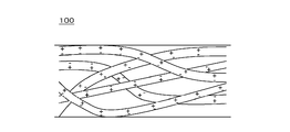
- FIG. 10 is a schematic diagram of a conventional air filter medium in a charged state.
- the air filter medium 100 obtained by subjecting the nonwoven fabric to charging treatment has fibers having positive charges and negative charges dispersed in a random manner (see, for example, Patent Document 2). ).
- JP 2008-000682 A JP-A-61-211027
- an object of the present invention is to provide an air filter medium with improved collection performance by providing a directional electric field on a nonwoven fabric and applying sufficient electrostatic force to dust particles.
- an air filter medium includes a base material and a fine fiber layer provided on the surface of the base material, and the fine fiber layer includes a plurality of fine fibers. It is a multilayer structure composed of aggregates.
- the volume resistivity of the polymer forming the fine fibers is 10 ⁇ 16 ⁇ cm or more and the dielectric loss tangent is 0.001 or less, and the charge is distributed to 90% or more of the entire area in the plane direction of each fine fiber aggregate. ing.
- the fine fibers in the local portion are laminated in the laminating direction with the first fine fiber aggregate having a lot of positive charges and the second fine fiber aggregate having a lot of negative charges. It is characterized by being. This achieves the intended purpose.
- a collection of fine fibers having positive and negative charges is laminated, so that a high electric field strength having directionality in the lamination direction can be obtained.
- a fiber can attract a dust particle strongly and can improve a collection efficiency remarkably.
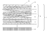
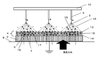
- FIG. 1 is a schematic cross-sectional view of an air filter medium according to Embodiment 1.
- FIG. FIG. 2 is a schematic diagram in a charged state of fine fibers of the air filter medium in the first embodiment.
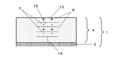
- FIG. 3 is a schematic diagram in the charged state of the air filter medium in the first embodiment.
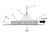
- FIG. 4 is a diagram showing a method for manufacturing the air filter medium in the first embodiment.
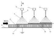
- FIG. 5 is a diagram illustrating a multilayer manufacturing method for an air filter medium in the first embodiment.
- FIG. 6 is a view of the manufacturing process of the air filter medium according to the second embodiment as viewed from A of FIG.
- FIG. 7 is a view of the manufacturing process of the air filter medium according to the second embodiment as viewed from B of FIG.
- FIG. 8 is a view of the spinning trajectory in the first nozzle row of the air filter medium according to the second embodiment as viewed from B in FIG. 5.
- FIG. 9 is a diagram showing the results of evaluating the fiber diameter, the filter medium collection efficiency, and the state of charge distribution in the examples.
- FIG. 10 is a schematic view of a conventional air filter medium in a charged state.
- An air filter medium includes a base material and a fine fiber layer provided on the surface of the base material, and the fine fiber layer is a multilayer structure including a plurality of fine fiber aggregates.
- the volume resistivity of the polymer forming the fine fiber is 10 ⁇ 16 ⁇ cm or more and the dielectric loss tangent is 0.001 or less, and the charge distribution is distributed over 90% of the entire area of each fine fiber aggregate in the plane direction. . Furthermore, in the laminating direction in the local portion, the first fine fiber aggregate having a lot of positive charges and the second fine fiber aggregate having a lot of negative charges are laminated. It is characterized by that.
- the air filter medium according to the embodiment of the present invention is characterized in that the first fine fiber aggregates and the second fine fiber aggregates are alternately laminated in three or more layers.
- the fine fiber layer sandwiched between the uppermost surface and the lowermost surface can have higher electric field strength with respect to the laminating direction of the air filter medium, the fine fibers strongly attract and adsorb dust particles. And the collection efficiency can be remarkably improved.
- the air filter medium according to the embodiment of the present invention is characterized in that the local bias of the charge is surrounded by the reverse charge in the planar direction and the stacking direction inside the fiber layer assembly. To do.
- the air filter medium according to the embodiment of the present invention is characterized in that the fine fibers are made of polystyrene.
- the charged state of the fiber layer can be maintained for a long time.
- the air filter medium according to the embodiment of the present invention may be composed of fibers having an average fiber diameter of the fine fiber layer of 100 nm to 2000 nm.
- the smaller the fiber diameter the less resistance the air collides with the fiber during ventilation, so the amount of fiber in the space at the same pressure loss can be increased. That is, as the fiber diameter is thinner, more fibers can be used. For this reason, the pores can be made denser, and the dust particle collection efficiency by mechanical collection can be improved. Furthermore, since the electric field strength between fibers becomes strong, the collection efficiency of dust particles by electrostatic force can be improved. As a result, the collection efficiency can be further improved.
- FIG. 1 is a schematic cross-sectional view of an air filter medium according to Embodiment 1.
- FIG. FIG. 2 and FIG. 3 are schematic diagrams in a charged state of fine fibers of the air filter medium in the first embodiment.
- the air filter medium 1 has a base material 2 and a fine fiber layer 4 composed of fine fibers 3.
- the first feature of the air filter medium 1 in the present embodiment is that the fine fiber layer 4 is a multilayer structure composed of a plurality of fine fiber aggregates 5 as shown in FIG.
- the charge is distributed over 90% of the entire area in the plane direction.
- the first fine fiber assembly 6 which is a fiber assembly having a lot of positive charges and the second fiber assembly having a lot of negative charges.
- the fine fiber aggregates 7 are alternately laminated. Thereby, as shown in FIG. 3, polarization can be formed in the lamination direction in the fine fiber layer 4.
- the fine fiber aggregate 5 refers to both the first fine fiber aggregate 6 and the second fine fiber aggregate 7.
- the second feature of the air filter medium 1 in the present embodiment is that the material of the fibers forming the fine fibers 3 satisfies the conditions that the volume resistivity is 10 ⁇ 16 ⁇ cm or more and the dielectric loss tangent is 0.001 or less.
- the polymer was used. Note that “ ⁇ ” is an operator representing a power. The above represents 10 to the 16th power.
- the volume resistivity of the fibers forming the fine fibers 3 is determined by measuring in accordance with ASTM D257 (standard established by the American Test Materials Association) and the dielectric loss tangent is measured in accordance with ASTM D150 (standards established by the American Test Materials Association). It is done.
- the volume resistivity is lower than 10 ⁇ 16 ⁇ cm, the fiber is not sufficiently charged, and the dust particle collection efficiency is lowered.
- the dielectric loss tangent is greater than 0.001, the stability of the charge is deteriorated, and when exposed to water vapor, the charge disappears and the dust particle collection efficiency is lowered.
- the volume resistivity is more preferably 10 ⁇ 16 ⁇ cm to 10 ⁇ 18 ⁇ cm.
- polystyrene examples include polypropylene (PP), polyethylene (PE), polycarbonate (PC, PolyCarbonate), polystyrene (PS, Polystyrene), polyphenyl ether (PPE, PolyPhenylEther), polyphenylene oxide (PPO).
- PP polypropylene
- PE polyethylene
- PC polycarbonate
- PS polystyrene
- PS polystyrene
- PPE Polyphenyl ether
- PPO polyphenylene oxide
- PolyPhenyleneOxide Polyphenylsulfone (PPSU, PolyPhenylSulfone), Polytetrafluoroethylene (PTFE, PolyTetraFluoroEthylene), Perfluoroalkoxyalkane (PFA, PerFluoro Alkoxyl Alkylene Fluoroethylene-Alkane Fluoroethylene-Polyethylene Alkane Tetraethylene) (ETFE, Ethylene-TetraFluoroEthylenecopolymer), perfluoro ethylene - poly pen copolymer (FEP, PerfluoroEthylenepolypencopolymer), ethylene - chlorotrifluoroethylene copolymer (ECTFE, Ethylene-ChloroTriFluoroEthylenecopolymer) or the like can be used or mixtures thereof.
- ECTFE Ethylene-ChloroTriFluoroEthylenecopolymer
- the production method of the fine fiber 3 constituting the fine fiber layer 4 using these polymers is not particularly limited as long as it is a spinning method of a fiber having a nano-order fiber diameter, but an electrostatic spinning method is preferable.
- the electrospinning method a high voltage is applied to the tip of the nozzle containing the polymer solution, and the polymer solution is sprayed onto the substrate surface charged to the ground or minus, causing the polymer to become fine fibers in the process of scattering the polymer solution.
- this method includes a process of applying a high voltage, the fine fiber 3 can be charged without separately performing a charging process by using a polymer that satisfies the above-described conditions.
- the above-mentioned conditions are conditions in which the volume resistivity is 10 ⁇ 16 ⁇ cm or more and the dielectric loss tangent is 0.001 or less.
- the nonwoven fabric can be damaged by charging and the fine fiber 3 can be charged without lowering the collection efficiency due to leakage, the collection efficiency can be improved.
- one fiber and one fiber can be charged, it is possible to increase the amount of electric charge of the fiber and improve the dust collecting performance as compared with separately performing the charging process.
- FIG. 4 is a diagram showing a method for manufacturing the air filter medium in the first embodiment.
- the manufacturing facility includes a transport unit 8 that transports the substrate 2 in the horizontal direction and a nozzle 9 that is positioned above the transport unit 8.
- the nozzle 9 sprays a polymer solution in order to form the fine fiber layer 4 on the surface which is the upper surface of the flat substrate 2 conveyed by the conveying unit 8.
- the conveying unit 8 In the manufacture of the air filter medium 1, first, while the flat substrate 2 is conveyed by the conveying unit 8, a polymer solution is discharged toward the substrate 2 in order to form the fine fiber layer 4 from the nozzle 9. .
- a voltage of about +20 KV is applied to the nozzle, and the transport unit 8 is grounded.
- a high polymer solution is drawn from the nozzle 9 to the base material 2 and the fine fibers 3 to be formed are deposited on the surface of the base material 2 to obtain the fine fiber layer 4.
- the conveyance part 8 is not specified, it may be a conveyor that can convey fibers.
- the solvent for dissolving the polymer is not particularly limited as long as it is compatible with the polymer and can be dissolved.
- the solvent include water, alcohols, organic solvents and the like. Specific alcohols and organic solvents include acetone (acetone), chloroform (chloroform), ethanol (ethanol), isopropanol (isopropanol), methanol.
- the solvent used is a highly polar solvent, and the charging of the polymer can be promoted by a charging method different from the voltage application from the nozzle. Details will be described later.
- a solvent can be roughly classified into protic (which can supply hydrogen ions) or aprotic.
- the approximate polarity can be classified depending on whether a hydrogen bond can be formed with other substances.
- the highly polar solvent used in the present invention is an aprotic solvent capable of forming a protic or hydrogen bond.
- solvents include acetone, ethanol, isopropanol, methanol, benzyl alcohol, propanol, phenol, pyridine, acetic acid, formic acid, N, N-dimethylformamide (DMF), N, N-dimethylacetamide (DMAc), 1,1 , 1,3,3,3-hexafluoro-2-propanol (HFIP), trifluoroacetic acid (TFA), acetonitrile, diethyl ether, or the like, or mixtures thereof.
- DMF N-dimethylformamide
- DMAc N, N-dimethylacetamide
- HFIP 1,1 , 1,3,3,3-hexafluoro-2-propanol
- TFA trifluoroacetic acid
- acetonitrile diethyl ether, or the like, or mixtures thereof.
- the process of charging the polymer includes a process of charging by a voltage applied to the nozzle and a process of charging when the solvent is vaporized.
- the sign of the charge obtained by the process of charging upon vaporization of the solvent is determined by the combination of the polymer and solvent used.
- a method for confirming the obtained charge a method using a charged toner shown in [Example] described later is used.
- the method for forming the first fine fiber aggregate 6 and the second fine fiber aggregate 7 differs depending on the solvent used.
- a solvent to be used there are a nonpolar solvent and a polar solvent.
- the applied voltage to the nozzle 9 is used as a pulse power source, and the applied voltage to the nozzle 9 is changed depending on time to form the fine fiber aggregate 5.
- the first fine fiber assembly 6 is formed, and when a negative voltage is applied to the nozzle 9, the second fine fiber assembly 7 is formed.
- a polar solvent When a polar solvent is used, it is further divided into two cases. The first is a case where both the process of charging by the voltage applied to the nozzle 9 and the process of charging when the polar solvent is vaporized have the same charge (both processes are charged positively or negatively charged). The second is a case where the process of charging by the voltage applied to the nozzle 9 and the process of charging when the polar solvent is vaporized are opposite charges (the charges charged in both processes are different). In this embodiment, the case of the same charge is described, and the case of the reverse charge is described in Embodiment 2.
- FIG. 5 is a diagram showing a multilayer manufacturing method of the air filter medium in the first embodiment.
- a plurality of nozzles 9 are provided in a line along the transport direction of the transport unit 8, and the first nozzle array 10, the second nozzle array 11, and the third nozzle array 12 are sequentially arranged from the transport direction.
- both the process of charging by the voltage applied to the nozzle 9 and the process of charging when the polar solvent is vaporized have the same charge. Therefore, the first fine fiber aggregate 6 and the second fine fiber aggregate 7 can be forcibly created separately by changing the polarity of the voltage applied to the nozzle 9 in the odd and even rows.
- the applied voltage of the nozzle 9 is performed from positive, but may be started from negative.
- the manufactured air filter medium 1 can form a fine fiber layer 4 having a multilayer structure in which fine fiber aggregates 5 whose electric charges are biased in the local lamination direction are alternately laminated.
- polarization can be formed in the lamination direction in the fine fiber layer 4, an electric field having high strength can be formed in the lamination direction.
- the first fine fiber aggregate 6 is charged to a positive pole (charge so that the positive charge increases), and the second fine fiber aggregate 7 is charged to a negative polarity (negative It is charged to increase the charge).
- the nonpolar dust particles are dielectrically polarized, and a negative polarity is generated on the first fine fiber assembly 6 side and a positive polarity is biased on the second fine fiber assembly 7 side.
- the dust particle end portion side biased to the positive polarity is attracted to the second fine fiber aggregate 7 by electrostatic force and collected. Since the second fine fiber aggregate 7 is configured by entangled and piled up the fine fibers 3, the probability that the dielectrically polarized dust particles are adsorbed is improved, and the collection efficiency is increased.
- the fine fibers 3 can collect the dust particles. That is, dust particles having negative polarity can be collected by the first fine fiber assembly 6, and dust particles having positive polarity can be collected by the second fine fiber assembly 7. , The collection efficiency can be remarkably improved.
- the direction of the electrostatic force received from the electric field is reversed depending on the polarity of the charged electric charge of the dust particles, resulting in a difference in the speed of passing through the pores.
- dust particles having a positive charge are accelerated, but dust particles having a negative charge are decelerated.
- dust particles having different polarities collide with each other and agglomerate to increase the particle diameter, thereby improving the collection efficiency of the dust particles.
- the base material 2 that forms the air filter medium 1 is a member that serves as a support for supporting the fine fiber layer 4.
- the substrate 2 includes pulp fibers, resin fibers, carbon fibers and inorganic fibers, or at least one of them manufactured by a spunbond method, a dry or wet method, a melt blown method, a spunbond method, an airlaid method, or the like. Constructed from non-woven fabric.
- the average diameter of the fibers constituting the substrate 2 is preferably about 1 ⁇ m to 30 ⁇ m.
- the average fiber diameter is smaller than 1 ⁇ m, the strength is weak, and when it is larger than 30 ⁇ m, the space between the fibers increases, and the fine fibers 3 forming the fine fiber layer 4 penetrate deep into the base material 2 to increase the pressure loss. is there.
- the material, shape and length of the substrate are not particularly limited, but if the stiffness of the nonwoven fabric is too low, the pleating process becomes difficult and the productivity is lowered.
- glass fiber or cellulose fiber is preferable.
- the fine fiber aggregate 5 is composed of three or more layers.
- the inner layer 15 sandwiched between the uppermost layer 13 and the lowermost layer 14 has a higher electric field strength because it is sandwiched between charges opposite to the stacking direction. Therefore, dust collection efficiency increases.
- the electrostatic force from the inside acts on the outer layer, so that the fine fiber 3 is not easily affected by the neutralization of electric charge and has a high collection efficiency. You can maintain the period.
- the filter medium having a plurality of electric fields in the laminating direction can be constituted by laminating two or more kinds of non-woven fabrics having different polarities on the front surface and the back surface.
- the pressure loss of the filter medium is high because an adhesive or heat bonding is required.
- the air filter medium 1 of the present invention a plurality of first fine fiber aggregates 6 and second fine fiber aggregates 7 having different polarities are alternately laminated in the fine fiber layer 4. According to this configuration, it is not necessary to laminate a charged non-woven fabric by adhesion, and deterioration of air permeability due to blockage of pores can be suppressed, so that pressure loss can be reduced.
- the charge is surrounded in the plane direction and the stacking direction (a local bias of a certain charge is surrounded by the reverse charge). It is characterized in that That is, it has a configuration in which either one of the positive and negative charges is increased and the larger charge is surrounded by the smaller charge.
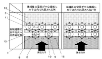
- FIG. 6 is a diagram of the manufacturing process of the air filter medium according to the second embodiment as viewed from A of FIG. More specifically, description will be made with reference to Fig. 6 [the conveyance direction in Fig. 4 and a diagram viewed from A (the first nozzle row 10 viewed from the upstream side of the conveyor)]. Since the center fiber 19 spun immediately below the nozzle 9 where the distance between the nozzle 9 to which the high voltage is applied and the base material 2 is close is charged by the electric field between the nozzle 9 and the base material 2, On the other hand, the end fibers 16 that are spun to the outer peripheral portion concentrically extending from directly below the nozzle 9 are not easily affected by the electric field created by the nozzle 9 and the base material 2, and vaporize the polar solvent.
- opposite charges can be imparted at the location of the center fiber 19 where the distance between the nozzle 9 and the substrate 2 is short and the location of the end fiber 16.
- it is positive and negative.
- Charged polymers must have a dielectric loss tangent of 0.001 or less Therefore, once held, the charges are maintained without being released and recombined, and therefore, by providing the gap between the nozzles 9 so that the end fibers 16 overlap, the conveying direction on one layer as shown in FIG. It is possible to form a region in which only the end fibers 16 that are spun to the outer peripheral portion exist, and by changing the arrangement of the nozzles 9, the first fine fiber aggregate 6 and the second fine fiber aggregate 7.
- a charged layer having the same polarity as the polarity of the nozzle 9 is formed in the stacking direction. It can be formed to surround the charged portion upon evaporation of the polar solvent.
- FIG. 7 is a view of the manufacturing process of the air filter medium according to the second embodiment as viewed from FIG. 5B.
- the nozzle 9 of the lower first nozzle array 10 and the nozzle 9 of the upper second nozzle array 11 Arrange the positions of.
- the nozzles 9 of the second nozzle row 11 are arranged at the center position between the nozzles 9 of the first nozzle row 10.
- the diameter of the center fiber 19 is the diameter ⁇ of the center fiber and the distance between the center fibers 19 is the distance ⁇ between the center fibers, the diameter of the center fiber ⁇ ⁇ the distance ⁇ between the center fibers, The charge of the end fibers 16 is surrounded by the charge of the center fibers 19 in the second nozzle array 11 in the nozzle array 10.
- a charge bias can be formed in a band shape by a single nozzle row in the plane direction, and a state of being sandwiched by reverse charges due to the arrangement of the upper and lower nozzle rows in the stacking direction.
- a local bias of a certain charge is surrounded by the opposite charge even in the plane direction of the produced fine fiber assembly 5.
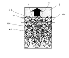
- FIG. 8 is a view of the spinning trajectory at the first nozzle row of the air filter medium according to the second embodiment as viewed from B.
- the center fiber 19 is formed of the center fiber that is meandered by the movement of the first nozzle row 10 and the transport of the base material 2.
- the first charge concentration portion 17 also meanders along the track 20 of the center fiber.
- the end fiber 16 is spun into a second charge concentration portion 18 where the center fiber track 20 does not overlap between the nozzles 9 in the first nozzle row 10.
- the second charge concentration portion 18 can be surrounded by the first charge concentration portion 17 by adjusting the diameter ⁇ of the center fiber and the distance ⁇ between the center fibers. Further, as shown in FIG.
- the arrangement of the nozzles 9 is different between the first nozzle row 10 and the second nozzle row 11, and the first charge concentration portion 17 can be spun on the upper layer of the second charge concentration portion 18. it can. Accordingly, the second charge concentration portion 18 can be three-dimensionally surrounded by the first charge concentration portion 17 by spinning into a multilayer structure composed of a plurality of fine fiber assemblies 5.
- the uppermost layer 13 and the lowermost layer 14 are the second fine fiber aggregate 7, and the inner layer 15 is the first fine fiber aggregate.
- This is a fiber assembly 6.
- FIG. 6 a state in which the second charge concentration portion 18 is surrounded by the first charge concentration portion 17 also in the planar direction of the first fine fiber aggregate 6 is realized. That is, the negative charge is three-dimensionally surrounded by the positive charge.
- a state in which positive charges are included in negative charges may be realized. This can be produced by adjusting the spinning amount of the center fiber 19 and the end fiber 16 per unit time, the center fiber diameter ⁇ and the distance ⁇ between the center fibers, the moving speed of the nozzle 9, the transport speed of the substrate 2, and the like. It is.
- the local charge is strengthened, so that a strong electric field is generated in both the planar direction and the stacking direction. Can be formed. That is, the particle collecting performance of the air filter medium 1 can be remarkably improved by improving the dielectric polarization effect of the passing dust particles and the Coulomb force of the fine fiber layer. Further, it becomes difficult to release charges included in the plane direction, and the charged state can be maintained for a long time.
- the collection efficiency of dust particles can be increased, the discharge of charge from the atmosphere and the end face of the fine fiber layer 4 is reduced, and the charged state of the fine fiber layer can be maintained for a longer time.
- the air filter medium 1 is preferably composed of fibers having an average fiber diameter of the fine fibers 3 of 100 to 2000 nm. If the fiber diameter is smaller than 100 nm, the self-supporting property is weak and it is easy to break. On the other hand, when the fiber diameter is larger than 2000 nm, the pores of the three-dimensional network structure formed by the fine fibers 3 are increased, and the Coulomb force that attracts dust in the atmosphere is weakened. Absent. More preferably, the average fiber diameter of the fine fibers 3 is 500 nm to 1500 nm.
- the pores can be made smaller, so that the collection efficiency by mechanical collection such as blocking or diffusion can be improved. Furthermore, since the distance between the fine fibers 3 is shortened, the electric field strength is increased, and the collection efficiency by electrostatic force can be improved. As a result, the collection efficiency can be further improved. Moreover, since the change of the air flow in the fine fiber 3 vicinity can be made small by making a fiber diameter thin, a turbulent flow can be suppressed and a pressure loss can be reduced.
- the curvature is increased, the charge density on the surface of the fine fiber 3 is increased, and the electrostatic force is increased, so that dust particles in the vicinity of the fine fiber 3 are easily sucked.
- the dust particle collection efficiency of the air filter medium 1 can be improved.
- the fiber diameter here is almost a normal distribution, and the numerical value of the fiber diameter is a numerical value of the center diameter including the variation of the standard deviation.
- the surface of the obtained filter medium was photographed with a scanning electron microscope (magnification 10,000 times), 20 fiber diameters were measured from the image, and an average value was calculated.
- the collection efficiency of dust particles is the number of particles with a particle diameter of 0.3 to 0.5 ⁇ m in the air dust upstream and downstream of the filter medium where the filter medium is placed in the duct and the air velocity at the passage surface of the filter medium is 6.5 cm / sec. Measurement was performed three times per sample with a particle counter (manufactured by Kanomax Co., Model 3887), and calculation was performed from the ratio of the number of particles on the upstream side and downstream side. In parallel with the evaluation of the collection efficiency, the pressure loss was obtained by reading the difference in static pressure upstream and downstream of the filter medium with a differential pressure gauge.
- QF value was calculated from the following calculation formula from the measured collection efficiency and pressure loss. The larger the QF value, the higher the performance as an air filter medium.
- Example 1 A filter medium was produced by the manufacturing method shown in the first embodiment. Fine fiber 3 is used as base material 2 by using a polyethylene terephthalate (PET) non-woven fabric having a weight per unit area of 98 g / m 2 and a polymer solution of 24% by weight of polystyrene dissolved in N, N-dimethylacetamide. A filter medium on which the fine fiber layer 4 was formed was obtained by spinning. Thereafter, the fiber diameter, the collection efficiency of the filter medium, and the state of charge distribution were evaluated. FIG. 9 is a diagram showing the results of evaluating the fiber diameter, the collection efficiency of the filter medium, and the state of charge distribution in the examples.
- PET polyethylene terephthalate
- Example 1 A 25 wt% polymer solution in which polyethersulfone was dissolved in N, N-dimethylacetamide was spun in the same manner as in Example 1 to obtain a filter medium. Thereafter, the fiber diameter, the collection efficiency of the filter medium, and the state of charge distribution were evaluated. The evaluation results are shown in FIG.
- Comparative Example 2 A 20 wt% polymer solution in which polyvinylidene fluoride was dissolved in N, N-dimethylacetamide was spun in the same manner as in Example 1 to obtain a filter medium. Thereafter, the fiber diameter, the collection efficiency of the filter medium, and the state of charge distribution were evaluated. The evaluation results are shown in FIG.
- Example 1 In Example 1 using polystyrene having a volume resistance of 10 ⁇ 16 ⁇ cm or more and a dielectric loss tangent of 0.001 or less, a charge distribution in which the aggregates are alternately stacked was confirmed, and a high QF value was exhibited.
- the charged toner does not adhere and the QF value is low.
- the air filter medium of the present invention significantly improves the collection efficiency, can be maintained for a long time, and has a low pressure loss. Therefore, it is expected to be utilized as an air filter for home use or office use, and an air purifying apparatus equipped with this air filter.
Landscapes
- Chemical & Material Sciences (AREA)
- Chemical Kinetics & Catalysis (AREA)
- Filtering Materials (AREA)
- Nonwoven Fabrics (AREA)
Abstract
La présente invention concerne un milieu filtrant (1) pour un filtre à air, qui est pourvu d'un matériau de base (2) et d'une couche de fibres fines (4) disposée sur la surface du matériau de base (2), la couche de fibres fines (4) étant une structure multicouche comprenant une pluralité d'agrégats de fibres fines (5). La résistivité volumique des polymères formant des fibres fines (3) est de 10^16 Ωcm ou plus, la tangente de perte est de 0 001 ou moins, et la charge de chaque agrégat de fibres fines (5) est distribuée sur 90 % ou plus de la surface totale dans la direction planaire. De plus, la présente invention est caractérisée en ce que des premiers agrégats de fibres fines (6) dans lesquels les fibres fines (3) ont principalement des charges positives et des seconds agrégats de fibres fines (7) dans lesquels les fibres fines (3) ont principalement des charges négatives, sont superposés les uns sur les autres dans une direction de stratification au niveau de parties locales, ce qui permet d'augmenter nettement les performances de collecte.
Applications Claiming Priority (4)
| Application Number | Priority Date | Filing Date | Title |
|---|---|---|---|
| JP2016-056463 | 2016-03-22 | ||
| JP2016056463 | 2016-03-22 | ||
| JP2017-036226 | 2017-02-28 | ||
| JP2017036226A JP2017170429A (ja) | 2016-03-22 | 2017-02-28 | エアフィルタ濾材 |
Publications (1)
| Publication Number | Publication Date |
|---|---|
| WO2017164112A1 true WO2017164112A1 (fr) | 2017-09-28 |
Family
ID=59900561
Family Applications (1)
| Application Number | Title | Priority Date | Filing Date |
|---|---|---|---|
| PCT/JP2017/010904 Ceased WO2017164112A1 (fr) | 2016-03-22 | 2017-03-17 | Milieu filtrant pour filtre à air |
Country Status (1)
| Country | Link |
|---|---|
| WO (1) | WO2017164112A1 (fr) |
Cited By (1)
| Publication number | Priority date | Publication date | Assignee | Title |
|---|---|---|---|---|
| CN113797651A (zh) * | 2021-09-30 | 2021-12-17 | 青岛中科凯尔科技有限公司 | 一种提高普通滤材过滤性能的方法 |
Citations (9)
| Publication number | Priority date | Publication date | Assignee | Title |
|---|---|---|---|---|
| JPS5876118A (ja) * | 1981-10-30 | 1983-05-09 | Koken Kk | 多層構造フイルタ |
| JPS61181511A (ja) * | 1985-02-06 | 1986-08-14 | Toray Ind Inc | 濾過材 |
| JPS62102809A (ja) * | 1985-10-28 | 1987-05-13 | Mitsui Petrochem Ind Ltd | エレクトレツト化不織布フイルタ− |
| JPS62197118A (ja) * | 1986-02-24 | 1987-08-31 | Toray Ind Inc | 積層エレクトレツトフイルタ |
| JPH04326911A (ja) * | 1991-04-25 | 1992-11-16 | Toyobo Co Ltd | エレクトレットフィルターの製造方法 |
| JPH05154318A (ja) * | 1991-12-10 | 1993-06-22 | Toshiba Corp | 空気清浄器用集塵フィルタ |
| WO1994012262A1 (fr) * | 1992-11-23 | 1994-06-09 | W.L. Gore & Associates, Inc. | Materiau de filtration turboelectrique |
| JPH09114183A (ja) * | 1995-10-23 | 1997-05-02 | Ricoh Co Ltd | 摩擦帯電装置 |
| WO2013096672A1 (fr) * | 2011-12-21 | 2013-06-27 | E. I. Du Pont De Nemours And Company | Processus de pose de bandes fibreuses à l'aide d'un processus de filature centrifuge |
-
2017
- 2017-03-17 WO PCT/JP2017/010904 patent/WO2017164112A1/fr not_active Ceased
Patent Citations (9)
| Publication number | Priority date | Publication date | Assignee | Title |
|---|---|---|---|---|
| JPS5876118A (ja) * | 1981-10-30 | 1983-05-09 | Koken Kk | 多層構造フイルタ |
| JPS61181511A (ja) * | 1985-02-06 | 1986-08-14 | Toray Ind Inc | 濾過材 |
| JPS62102809A (ja) * | 1985-10-28 | 1987-05-13 | Mitsui Petrochem Ind Ltd | エレクトレツト化不織布フイルタ− |
| JPS62197118A (ja) * | 1986-02-24 | 1987-08-31 | Toray Ind Inc | 積層エレクトレツトフイルタ |
| JPH04326911A (ja) * | 1991-04-25 | 1992-11-16 | Toyobo Co Ltd | エレクトレットフィルターの製造方法 |
| JPH05154318A (ja) * | 1991-12-10 | 1993-06-22 | Toshiba Corp | 空気清浄器用集塵フィルタ |
| WO1994012262A1 (fr) * | 1992-11-23 | 1994-06-09 | W.L. Gore & Associates, Inc. | Materiau de filtration turboelectrique |
| JPH09114183A (ja) * | 1995-10-23 | 1997-05-02 | Ricoh Co Ltd | 摩擦帯電装置 |
| WO2013096672A1 (fr) * | 2011-12-21 | 2013-06-27 | E. I. Du Pont De Nemours And Company | Processus de pose de bandes fibreuses à l'aide d'un processus de filature centrifuge |
Cited By (1)
| Publication number | Priority date | Publication date | Assignee | Title |
|---|---|---|---|---|
| CN113797651A (zh) * | 2021-09-30 | 2021-12-17 | 青岛中科凯尔科技有限公司 | 一种提高普通滤材过滤性能的方法 |
Similar Documents
| Publication | Publication Date | Title |
|---|---|---|
| JP5762806B2 (ja) | ナノファイバーを用いたフィルター製造方法 | |
| JP5473144B2 (ja) | ナノファイバー製造方法 | |
| JP5637479B2 (ja) | ナノファイバーの製造装置 | |
| WO2010055668A1 (fr) | Assemblage de type feuille de fibres de petits diamètres, procédé pour sa production et appareil pour sa production | |
| JP6624588B2 (ja) | 積層不織布およびその製造方法 | |
| CN107150466B (zh) | 纤维层叠体及其制造方法 | |
| JP6624589B2 (ja) | 積層不織布の製造方法 | |
| US10413856B2 (en) | Stacked body | |
| JP2015112523A (ja) | エアフィルタ用濾材 | |
| CN107012586B (zh) | 无纺布、以及具备它的集尘过滤器、微生物或生物组织的培养基、以及化妆用品 | |
| CN106400303A (zh) | 层叠无纺布及空气净化机 | |
| US10464003B2 (en) | Filter | |
| JP5754703B2 (ja) | ナノファイバー不織布の製造方法及び装置 | |
| CN105771426B (zh) | 层叠无纺布及空气净化器 | |
| JP5946894B2 (ja) | ナノファイバーを用いたフィルター | |
| CN106256403A (zh) | 层叠无纺布、空气净化机及层叠无纺布的制造方法 | |
| CN106400302B (zh) | 层叠无纺布及空气净化机 | |
| JP6528243B2 (ja) | 不織布、空気清浄機、および不織布の製造方法 | |
| JP2017170429A (ja) | エアフィルタ濾材 | |
| JP2016168592A (ja) | 接着剤吹き付け装置 | |
| WO2013121733A1 (fr) | Filtre à air, purificateur d'air muni d'un filtre à air, et procédé pour la fabrication d'un filtre à air | |
| JP6551770B2 (ja) | 不織布およびそれを用いた空気清浄機、ならびに不織布の製造方法 | |
| JP2018066092A (ja) | 集合構造体の製造装置および集合構造体の製造方法 | |
| JP6590311B2 (ja) | 積層不織布および空気清浄機 | |
| JP2017225968A (ja) | エアフィルタ濾材 |
Legal Events
| Date | Code | Title | Description |
|---|---|---|---|
| NENP | Non-entry into the national phase |
Ref country code: DE |
|
| 121 | Ep: the epo has been informed by wipo that ep was designated in this application |
Ref document number: 17770154 Country of ref document: EP Kind code of ref document: A1 |
|
| 122 | Ep: pct application non-entry in european phase |
Ref document number: 17770154 Country of ref document: EP Kind code of ref document: A1 |