WO2017164128A1 - Structure de montage - Google Patents
Structure de montage Download PDFInfo
- Publication number
- WO2017164128A1 WO2017164128A1 PCT/JP2017/010969 JP2017010969W WO2017164128A1 WO 2017164128 A1 WO2017164128 A1 WO 2017164128A1 JP 2017010969 W JP2017010969 W JP 2017010969W WO 2017164128 A1 WO2017164128 A1 WO 2017164128A1
- Authority
- WO
- WIPO (PCT)
- Prior art keywords
- insertion hole
- opening region
- attachment
- claw
- mounting structure
- Prior art date
- Legal status (The legal status is an assumption and is not a legal conclusion. Google has not performed a legal analysis and makes no representation as to the accuracy of the status listed.)
- Ceased
Links
Images







Classifications
-
- G—PHYSICS
- G10—MUSICAL INSTRUMENTS; ACOUSTICS
- G10H—ELECTROPHONIC MUSICAL INSTRUMENTS; INSTRUMENTS IN WHICH THE TONES ARE GENERATED BY ELECTROMECHANICAL MEANS OR ELECTRONIC GENERATORS, OR IN WHICH THE TONES ARE SYNTHESISED FROM A DATA STORE
- G10H1/00—Details of electrophonic musical instruments
- G10H1/32—Constructional details
- G10H1/34—Switch arrangements, e.g. keyboards or mechanical switches specially adapted for electrophonic musical instruments
- G10H1/344—Structural association with individual keys
- G10H1/346—Keys with an arrangement for simulating the feeling of a piano key, e.g. using counterweights, springs, cams
-
- F—MECHANICAL ENGINEERING; LIGHTING; HEATING; WEAPONS; BLASTING
- F16—ENGINEERING ELEMENTS AND UNITS; GENERAL MEASURES FOR PRODUCING AND MAINTAINING EFFECTIVE FUNCTIONING OF MACHINES OR INSTALLATIONS; THERMAL INSULATION IN GENERAL
- F16B—DEVICES FOR FASTENING OR SECURING CONSTRUCTIONAL ELEMENTS OR MACHINE PARTS TOGETHER, e.g. NAILS, BOLTS, CIRCLIPS, CLAMPS, CLIPS OR WEDGES; JOINTS OR JOINTING
- F16B5/00—Joining sheets or plates, e.g. panels, to one another or to strips or bars parallel to them
- F16B5/07—Joining sheets or plates, e.g. panels, to one another or to strips or bars parallel to them by means of multiple interengaging protrusions on the surfaces, e.g. hooks, coils
-
- F—MECHANICAL ENGINEERING; LIGHTING; HEATING; WEAPONS; BLASTING
- F16—ENGINEERING ELEMENTS AND UNITS; GENERAL MEASURES FOR PRODUCING AND MAINTAINING EFFECTIVE FUNCTIONING OF MACHINES OR INSTALLATIONS; THERMAL INSULATION IN GENERAL
- F16B—DEVICES FOR FASTENING OR SECURING CONSTRUCTIONAL ELEMENTS OR MACHINE PARTS TOGETHER, e.g. NAILS, BOLTS, CIRCLIPS, CLAMPS, CLIPS OR WEDGES; JOINTS OR JOINTING
- F16B5/00—Joining sheets or plates, e.g. panels, to one another or to strips or bars parallel to them
- F16B5/10—Joining sheets or plates, e.g. panels, to one another or to strips or bars parallel to them by means of bayonet connections
-
- G—PHYSICS
- G10—MUSICAL INSTRUMENTS; ACOUSTICS
- G10B—ORGANS, HARMONIUMS OR SIMILAR WIND MUSICAL INSTRUMENTS WITH ASSOCIATED BLOWING APPARATUS
- G10B3/00—Details or accessories
- G10B3/12—Keys or keyboards; Manuals
-
- G—PHYSICS
- G10—MUSICAL INSTRUMENTS; ACOUSTICS
- G10H—ELECTROPHONIC MUSICAL INSTRUMENTS; INSTRUMENTS IN WHICH THE TONES ARE GENERATED BY ELECTROMECHANICAL MEANS OR ELECTRONIC GENERATORS, OR IN WHICH THE TONES ARE SYNTHESISED FROM A DATA STORE
- G10H1/00—Details of electrophonic musical instruments
- G10H1/32—Constructional details
- G10H1/34—Switch arrangements, e.g. keyboards or mechanical switches specially adapted for electrophonic musical instruments
Definitions
- the present invention relates to a mounting structure that couples parts using the elasticity of a material.
- the present invention relates to a key mounting structure of a keyboard device.
- Patent Document 1 proposes an attachment structure for a printed wiring board.
- One of the objects of the present invention is to provide an attachment structure capable of preventing unintentional separation between parts.
- An attachment structure includes: a first member having an attachment portion; and a second member having an insertion hole into which the attachment portion is inserted and fixed to the first member.
- the attachment portion has a flexible portion that can be inserted into the insertion hole, and a claw portion provided at one end of the flexible portion, and the insertion hole of the second member has a first end portion and a second end portion.
- the mounting portion inserted into the insertion hole is configured such that the claw portion protrudes from the first end portion, and the insertion hole of the second member is located on the first end portion side.
- the second opening region has a first side and a second side opposite to the first side, and one side of the first opening region on an extension of the first side Is formed so as continuous, the second side is provided opposite the obliquely relative to the first side.
- the mounting portion may be in contact with both the first side and the second side in a state where the first member is mounted on the second member.
- the first side and the second side may be in contact with the mounting portion so as to sandwich the mounting portion.
- the mounting portion may be in contact with the second side at a corner of the second opening region that is separated from the first side.
- the flexible portion may be less flexible in a direction perpendicular to the direction toward the first side than the flexibility in the direction toward the first side.
- the flexible portion has a side surface extending in a direction in which the insertion hole extends, and the claw portion projects from the first end portion, and the first end portion side is formed. It has a facing surface that is connected to the side and the side surface, and an angle formed by the side surface and the facing surface can be an obtuse angle.
- the first opening region is formed in a rectangular shape having first and second sides facing each other, and a third side and fourth side facing each other
- the second opening region is The first side of the first opening region and the first side of the second opening region are formed in a rectangular shape having the first side and the second side facing each other and the third side and the fourth side facing each other.
- the side may be continuous, and the third side of the second opening region may be included in a part of the third side of the first opening region.
- the first member may have a positioning portion for positioning with respect to the second member.
- the flexible part can be formed in a rod shape.
- the claw portion can be formed in the insertion hole so as to protrude toward the first side at the first end portion.
- a second attachment structure includes a first member having an attachment portion, and a second member having an insertion hole into which the attachment portion is inserted and fixed to the first member,
- the attachment portion of the first member has a flexible portion that can be inserted into the insertion hole, and a claw portion provided at one end of the flexible portion, and the insertion hole of the second member is connected to the first end portion.
- the attachment portion inserted into the insertion hole is configured such that the claw portion protrudes from the first end portion, and the insertion hole of the second member is the first end portion.
- the first opening region has a size that allows the claw portion to pass through
- the second opening region has a size that is connected to the first opening region and cannot pass the claw portion.
- the second opening region is a hook of the claw portion with respect to the second member in a state where the first member is attached to the second member. There has one side acting in the direction of increasing.
- the one side of the second opening region can be arranged obliquely with respect to the other side facing the one side.
- claw part has the opposing surface which faces the said 1st edge part side in the state protruded from the said 1st edge part,
- the said opposing surface is a said 2nd member.
- the keyboard device includes a frame, a plurality of keys extending in a longitudinal direction, a plurality of connecting members that rotatably connect the keys to the frame, the connecting members, and a connecting portion of the keys. And any one of the mounting structures described above, which is provided on at least one of the coupling members and the coupling portion of the frame.
- FIG. 1 shows the structure of the keyboard apparatus of one Embodiment of this invention. It is a block diagram which shows the structure of the sound source device of embodiment of FIG. It is a figure which shows an example which looked at the structure inside the housing
- FIG. 10 is a diagram showing an example of a configuration in which the second member in the mounting structure of the embodiment of FIG.
- FIG. 10 is a diagram showing an example of a configuration in which the second member in the mounting structure of the embodiment of FIG. 1 is cut along BB ′ shown in FIG. 9. It is a figure which shows an example which looked at the structure of the 2nd member in the attachment structure of embodiment of FIG. 1 from the back surface. It is a figure for demonstrating the upper end of the 1st opening part which the 2nd member in the attachment structure of embodiment of FIG. 1 has. It is a figure which shows the positional relationship of the 1st opening part which the 2nd member has in the attachment structure of embodiment of FIG. 1, and the nail
- FIG. 1 is a diagram illustrating a configuration of a keyboard device according to the present embodiment.
- the keyboard device 1 is an electronic keyboard instrument that emits sound in response to a user (player) key depression such as an electronic piano.
- the keyboard device 1 may be a keyboard-type controller that outputs control data (for example, MIDI) for controlling an external sound source device in response to a key depression.
- control data for example, MIDI
- the keyboard device 1 may not have a sound source device.
- the keyboard device 1 includes a keyboard assembly 10.
- the keyboard assembly 10 includes a plurality of keys 100 extending in the longitudinal direction.
- the plurality of keys 100 include a plurality of white keys 100w and a plurality of black keys 100b.
- the plurality of white keys 100w and the plurality of black keys 100b are arranged side by side. This arranged direction is called a scale direction.
- the number of keys 100 is 88.
- the number of keys 100 is not limited to such an example, and may be appropriately determined according to the embodiment.
- the white key 100w and the black key 100b are described without particular distinction, they may be simply referred to as “key 100”.
- “w” is added at the end of the reference sign, it means that the structure corresponds to the white key.
- “b” is appended to the end of the code, it means that the configuration corresponds to the black key.
- a part of the keyboard assembly 10 exists inside the housing 90.
- a portion of the keyboard assembly 10 covered by the casing 90 is referred to as a non-appearance portion NV, and a portion exposed from the casing 90 and visible to the user is referred to as an appearance portion PV.
- the appearance part PV is a part of the key 100 and indicates an area where the user can perform a performance operation.
- a portion of the key 100 that is exposed by the appearance portion PV may be referred to as a key body portion.
- a sound source device 70 and a speaker 80 are arranged inside the housing 90.
- the tone generator 70 generates a sound waveform signal when the key 100 is pressed.
- the speaker 80 outputs the sound waveform signal generated in the sound source device 70 to an external space.
- the keyboard device 1 may be provided with a slider for controlling the volume, a switch for switching timbres, a display for displaying various information, and the like.
- directions such as up, down, left, right, front, and back indicate directions when the keyboard device 1 is viewed from the performer when performing. Therefore, for example, the non-appearance part NV can be expressed as being located on the back side with respect to the appearance part PV. Further, the direction may be indicated with the key 100 as a reference, such as the key front end side and the key rear end side. In this case, the key front end side indicates the front side as viewed from the performer with respect to the key 100. The rear end side of the key indicates the back side viewed from the performer with respect to the key 100.
- the black key 100b can be expressed as a portion protruding upward from the white key 100w from the front end to the rear end of the key body of the black key 100b.
- FIG. 2 is a block diagram illustrating a configuration of the sound source device according to the embodiment.
- the sound source device 70 includes a signal conversion unit 710, a sound source unit 730, and an output unit 750.
- the sensor 300 is provided corresponding to each key 100, detects a key operation, and outputs a signal corresponding to the detected content. In this example, the sensor 300 outputs a signal according to the key depression amount in three stages. The key pressing speed can be detected according to the interval of this signal.
- the signal conversion unit 710 acquires the output signal of the sensor 300 (sensors 300-1, 300-2,..., 300-88 corresponding to the 88 key 100), and operates according to the operation state of each key 100. Generate and output a signal.
- the operation signal is a MIDI signal. Therefore, the signal conversion unit 710 outputs note-on according to the key pressing operation. At this time, the key number indicating which of the 88 keys 100 has been operated and the velocity corresponding to the key pressing speed are also output in association with the note-on.
- the signal conversion unit 710 outputs the key number and note-off in association with each other.
- a signal corresponding to another operation such as a pedal may be input to the signal conversion unit 710 and reflected in the operation signal.
- the sound source unit 730 generates a sound waveform signal based on the operation signal output from the signal conversion unit 710.
- the output unit 750 outputs the sound waveform signal generated by the sound source unit 730. This sound waveform signal is output to, for example, the speaker 80 or the sound waveform signal output terminal.
- FIG. 3 is an explanatory diagram when the configuration inside the housing in the present embodiment is viewed from the side.
- the keyboard assembly 10 and the speaker 80 are disposed inside the housing 90.
- the speaker 80 is disposed on the back side of the keyboard assembly 10.
- the speaker 80 is arranged to output a sound corresponding to the depressed key 100 toward the upper and lower sides of the housing 90.
- the sound output downward advances from the lower surface side of the housing 90 to the outside.
- the sound output upward passes through the space inside the keyboard assembly 10 from the inside of the housing 90, and is externally transmitted from the gap between the adjacent keys 100 in the exterior portion PV or the gap between the key 100 and the housing 90. Proceed to
- the keyboard assembly 10 includes a plurality of connecting portions 180, a hammer assembly 200, and a frame 500 in addition to the key 100 described above.
- the keyboard assembly 10 is a resin-made structure whose most configuration is manufactured by injection molding or the like.
- the frame 500 is fixed to the housing 90.
- each connection portion 180 includes a plate-like flexible portion 181 and a key-side support portion 183 that constitute the rear end portion of each key 100, and a rod-like flexible portion 185a.
- the plate-like flexible part 181 extends from the rear end of the key 100.
- the key side support portion 183 extends from the rear end of the plate-like flexible portion 181.
- the rod-like flexible portion 185 a connects the key side support portion 183 and the frame side support portion 585 of the frame 500.
- the rod-shaped flexible part 185 a is disposed between the key 100 and the frame 500.
- the key 100 can be rotated with respect to the frame 500 by bending the rod-shaped flexible portion 185a. That is, the rod-like flexible portion 185a corresponds to the “connecting member” of the present invention, and each key 100 is pivotally connected to the frame 500 by the rod-like flexible portion 185a of each connecting portion 180.
- the attachment portion described later is attached to both the joint portion between the rod-like flexible portion 185a and the key-side support portion 183 of the key 100 and the joint portion between the rod-like flexible portion 185a and the frame-side support portion 585 of the frame 500.
- a structure 20 (so-called snap fit) is provided.
- the mounting structure is designed so that the direction in which the snap-fit claw portion (claw portion 22 described later) is hooked and the longitudinal direction of the key 100 coincide. Since the snap-fit claw portion has a circumstance that it is desired to bend as much as possible, the longitudinal direction is more advantageous from the viewpoint of securing space than the scale direction in which the keys 100 are arranged with high density.
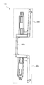
- FIG. 4 is a diagram illustrating a configuration of the structure body 185 including the rod-shaped flexible portion 185a according to the embodiment as viewed from the side surface.
- the structure 185 has a structure in which first members 20a described later are attached to both ends of a rod-like flexible portion 185a.
- a pair of first members 20 a are provided at both ends of the rod-like flexible portion 185 a so as to be opposite to each other. Therefore, by attaching one first member 20a to the key-side support portion 183 and attaching the other first member 20a to the frame-side support portion 585, the key-side support portion 183 and the frame-side support portion 585 can be connected to a bar.
- the flexible portion 185a can be coupled. Details of the mounting structure including the first member 20a will be described later.
- the key 100 includes a front end key guide 151 and a side key guide 153.
- the front end key guide 151 is slidably in contact with the front end frame guide 511 of the frame 500.
- the front end key guide 151 is in contact with the front end frame guide 511 on both sides of the upper and lower scale directions.
- the side key guide 153 is slidably in contact with the side frame guide 513 on both sides in the scale direction.
- the side key guide 153 is arranged in a region corresponding to the non-appearance portion NV on the side surface of the key 100 and exists on the key front end side with respect to the connection portion 180 (plate-like flexible portion 181). You may arrange
- the hammer assembly 200 is attached to the frame 500 so as to be rotatable. At this time, the shaft support part 220 of the hammer assembly 200 and the rotation shaft 520 of the frame 500 are slidably contacted at least at three points.
- the front end portion 210 of the hammer assembly 200 contacts the inner space of the hammer support portion 120 so as to be slidable in the front-rear direction.
- the sliding portion that is, the portion where the front end portion 210 and the hammer support portion 120 are in contact is located below the key 100 in the appearance portion PV (frontward from the rear end of the key body portion).
- a metal weight 230 is disposed on the back side of the rotation shaft.
- the weight portion 230 In a normal state (when the key is not pressed), the weight portion 230 is placed on the lower stopper 410, and the front end portion 210 of the hammer assembly 200 pushes the key 100 back.
- the weight portion 230 moves upward and collides with the upper stopper 430.
- the hammer assembly 200 applies weight to the key depression by the weight portion 230.
- the lower stopper 410 and the upper stopper 430 are formed of a buffer material or the like (nonwoven fabric, elastic body, etc.).
- the sensor 300 is attached to the frame 500 below the hammer support portion 120 and the front end portion 210. When the sensor 300 is crushed on the lower surface side of the front end portion 210 by the key depression, the sensor 300 outputs a detection signal. As described above, the sensor 300 is provided corresponding to each key 100.
- the attachment structure 20 of this embodiment is what is called a snap fit, and couples parts using the elasticity of material.
- a schematic configuration of the mounting structure 20 of the present embodiment will be described with reference to FIG.
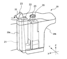
- FIG. 5 is a diagram showing a case where the configuration of the mounting structure 20 of the embodiment is viewed from an oblique direction. Specifically, FIG. 5 shows a state in which the first member 20a and the second member 20b constituting the attachment structure 20 are coupled. In FIG. 5, the description will be focused on only the portion of the attachment structure 20, but as described above, the first member 20 a is a member provided at both ends of the rod-shaped flexible portion 185 a as shown in FIG. 4.
- the second member 20b is a member constituting the mounting structure 20 in a pair with the first member 20a, and is a member provided on the key side support portion 183 and the frame side support portion 585 shown in FIG.
- the mounting structure 20 in this embodiment uses a combination of the first member 20a and the second member 20b.
- the first member 20 a includes a flexible portion 21, an attachment portion 23 having a claw portion 22 provided at the distal end of the flexible portion 21, and a positioning portion 25 connected to the flexible portion 21.
- the 2nd member 20b is provided with the 1st insertion hole 33 in which the attachment part 23 is inserted from the downward side, and the 2nd insertion hole 35 in which the positioning part 25 is inserted from the downward side.
- the upper end of the first insertion hole 33 corresponds to the first end of the present invention, and the lower end corresponds to the second end of the present invention.
- the mounting structure 20 is configured so that the first member 20a can be mounted from below the second member 20b. That is, in the present embodiment, the direction in which the first member 20a is attached to the second member 20b (hereinafter also referred to as “attachment direction”) is the vertical direction.
- attachment direction the direction in which the first member 20a is attached to the second member 20b
- the state where the first member 20a is mounted to the second member 20b is the first member as shown in FIG. A state in which 20a and the second member 20b are coupled to each other.
- the first member 20a is configured to be strongly coupled to the second member 20b as the flexible portion 21 bends, but it is preferable that this bend is as large as possible.
- the front-rear direction of the mounting structure 20 coincides with the longitudinal direction of the key 100 shown in FIGS. Since the key 100 is arranged at a high density in the scale direction (direction orthogonal to the longitudinal direction), there is little room to secure a space for greatly bending the first member 20a. Therefore, by making the front-rear direction of the mounting structure 20 coincide with the longitudinal direction of the key 100, the amount of bending of the first member 20a can be increased as much as possible, and space saving can be achieved.
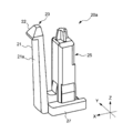
- FIG. 6 is a diagram illustrating an example of the configuration of the first member 20a in the mounting structure 20 of the present embodiment as viewed obliquely from above.
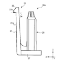
- FIG. 7 is a diagram illustrating an example of the configuration of the first member 20a in the mounting structure 20 of the present embodiment as viewed from the side.
- the first member 20a shown in FIGS. 6 and 7 corresponds to the claw side member in the mounting structure 20 of the present embodiment.
- the first member 20a has a substantially square columnar flexible portion 21 and a claw portion 22 provided at one end of the flexible portion 21, and has a mounting portion 23 and a flexible portion 21 extending in the mounting direction (that is, the vertical direction). And a connecting portion 27 for connecting the flexible portion 21 and the positioning portion 25 to each other.
- the flexible portion 21 is made of a flexible material.
- the flexible material is not particularly limited and may be appropriately selected depending on the embodiment.
- a plastic material can be used as the flexible material.
- the flexible portion 21 of the present embodiment is configured such that the length (thickness) in the direction along the X axis is shorter than the length (width) in the direction along the Y axis. Therefore, the flexibility of the flexible portion 21 is greatly deflected in the direction along the X axis (that is, the front-rear direction), and the direction along the Y axis (that is, the left-right direction) is larger than the direction along the X axis. It is designed to bend slightly. That is, the flexible portion 21 has a shape that is less flexible in the direction along the Y axis than the flexibility in the direction along the X axis.
- the flexible portion 21 is configured such that the claw portion 22 overlaps the second member 20b more deeply (that is, the amount of engagement increases) by increasing the flexibility in the direction along the X axis. ing.
- claw part 22 is a site
- claw part 22 which concerns on this embodiment is provided in the front-end
- the direction in which the claw portion 22 protrudes may not be limited to the front, and may be appropriately determined according to, for example, the configuration of the second member 20b (particularly, the position of the surface on which the claw portion 22 is hooked).
- the lower part of the attachment part 23 from the alternate long and short dash line 24 shown in FIG. 7 is called the flexible part 21, and the upper part is called the claw part 22.
- the flexible portion 21 and the claw portion 22 may be integrally formed, or may be configured by different members.
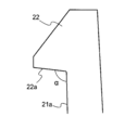
- the lower surface of the protruding portion (the surface located on the lower side: the facing surface of the present invention) 22a is the second member when the first member 20a is attached to the second member 20b. It is a site
- the lower surface 22a of the claw portion 22 receives the force in the Z-axis direction applied to the flexible portion 21, so that the first member 20a can be prevented from falling off from the second member 20b.
- FIG. 8A is a diagram illustrating an example of the structure of the hanging portion 22 in the mounting structure 20 of the present embodiment as viewed from the side.
- FIG. 8B is a diagram for explaining the operation of the claw portion 22 in the mounting structure 20 of the present embodiment.
- the lower surface 22a of the claw portion 22 and the front surface 21a of the flexible portion 21 (specifically, the flexible portion 21).
- the surface ⁇ is the surface facing the side where the lower surface 22a exists, and the angle ⁇ formed with the side surface connected to the lower surface 22a is an obtuse angle.
- the lower surface 22a of the claw portion 22 can correspond to a surface inclined in the positive direction of the Z axis (the direction of the arrow) with respect to the X axis shown in FIG.
- the lower surface 22 a of the claw portion 22 can correspond to a surface inclined upward with respect to the flexible direction of the flexible portion 21.
- FIG. 8B shows a state where the claw portion 22 is coming off from the opening peripheral edge portion 331 of the first insertion hole 33 on the upper surface 31a of the second member 20b.
- a force is applied to the claw portion 22 in the direction of the arrow by the elastic force of the flexible portion 21. Therefore, the claw portion 22 slides in the direction of the arrow in a state where the lower surface 22a is in contact with the corner of the upper surface 31a (specifically, the edge of the first insertion hole 33 described later), and the position indicated by the solid line Move to.
- the angle ⁇ formed by the lower surface 22a of the claw part 22 and the surface 21a of the flexible part 21 is an obtuse angle, so that the claw part that contacts the opening peripheral part 331 of the second insertion hole 35 is formed.
- the surface (lower surface 22a) of 22 is configured to be slidably inclined with respect to the opening peripheral edge portion 331 in a direction in which the claw portion 22 overlaps the second member 20b.
- the elastic force that tends to move forward of the flexible portion 21 is moved upward by the lower surface 22a of the claw portion 22. It is converted into the power of.
- the lower surface 22a of the claw portion 22 works in a direction to increase the amount of engagement of the claw portion 22 with the second member 20b (the length with which the claw portion 22 is superimposed on the second member 20b).
- the amount of self-recovering action (nail) Part pulling action) can be added.
- the positioning part 25 extends in the same direction as the attachment part 23, and is a part for determining the relative position of the attachment part 23 (particularly the claw part 22) with respect to the second member 20b.
- the positioning portion 25 and the flexible portion 21 of the attachment portion 23 are connected to each other on the rear end side in the mounting direction by a flat plate-like connecting portion 27. That is, the lower end portion of the positioning portion 25 and the lower end portion of the flexible portion 21 of the attachment portion 23 are connected by the connecting portion 27.
- the relative positional relationship between the first member 20a and the second member 20b is fixed by inserting the positioning portion 25 into the second insertion hole 35 of the second member 20b.
- the relative position of the hook portion 22 with respect to the second member 20b is constant, a stable hook amount can be ensured.
- FIG. 9 is a diagram illustrating an example of the configuration of the second member 20b in the mounting structure 20 of the present embodiment when viewed obliquely from above.
- FIG. 10 is a diagram illustrating an example of the configuration of the second member 20b in the mounting structure 20 of the present embodiment as viewed from above.
- FIG. 11 is a diagram showing an example of a cross section taken along line A-A ′ shown in FIG. 10 of the second member 20 b in the mounting structure 20 of the present embodiment.
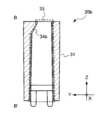
- FIG. 12 is a view showing an example of a cross section taken along line B-B ′ shown in FIG. 10 of the second member 20 b in the mounting structure 20 of the present embodiment.
- FIG. 13 is a diagram illustrating an example when the configuration of the second member 20b in the mounting structure 20 of the present embodiment is viewed from the back (back side).
- the second member 20b shown in FIGS. 9 to 13 corresponds to a member on the receiving side with respect to the first member 20a in the mounting structure 20 of the present embodiment.
- the second member 20 b includes a main body 31, and a first insertion hole 33, a second insertion hole 35, a notch 37, and a protrusion 39 provided in the main body 31.
- the main body portion 31 of the present embodiment is a main body portion of the second member 20b and corresponds to the key side support portion 183 and the frame side support portion 585 shown in FIG.
- the first insertion hole 33 extends in the mounting direction of the first member 20a with respect to the second member 20b (that is, the vertical direction) and is provided so as to penetrate the main body 31.
- the attachment portion 23 of the first member 20a is inserted into the first insertion hole 33 from below the main body portion 31.
- the length of the mounting portion 23 in the mounting direction (Z-axis direction) of the flexible portion 21 corresponds to the length of the first insertion hole 33, thereby causing the claw portion 22 to protrude from the first insertion hole 33,
- the claw portion 22 can be hooked on the opening peripheral edge on the upper side of the first insertion hole 33.
- the claw portion 22 of the first member 20 a overlaps the upper surface 31 a of the main body portion 31, whereby the first member 20 a and the second member 20 b are coupled.
- the first insertion hole 33 can correspond to the internal space of the main body portion 31 formed for inserting the attachment portion 23 (the flexible portion 21 and the claw portion 22) of the first member 20a.
- the second member 20b of the present embodiment has two inclined surfaces as the inner wall surface of the first insertion hole 33, that is, a first inclined surface 34a and a second inclined surface 34b.
- the first inclined surface 34 a is an inclined surface that constitutes a part of the front wall surface when the cross section including the X axis is viewed from the left side
- the second inclined surface 34 b is As shown in FIG. 12, when the cross section containing a Y-axis is seen from the front side, it is an inclined surface which comprises a part of wall surface of the right side (the direction of the arrow of a Y-axis). Any inclined surface is provided so that the width of the first insertion hole 33 becomes narrower as it goes upward when the cross section of the first insertion hole 33 is viewed from the side.
- the first inclined surface 34 a and the second inclined surface 34 b are disposed at a position where the claw portion 22 corresponding to the distal end portion of the attachment portion 23 contacts when the attachment portion 23 is inserted into the first insertion hole 33. Therefore, when the attachment portion 23 is inserted into the first insertion hole 33, the claw portion 22 slides on the respective inclined surfaces, so that the position of the claw portion 22 (position with respect to the positioning portion 25) is front and back. Move in the left or right direction.
- the upper surface of the claw portion 22 is in contact with each inclined surface.
- the “upper surface of the claw portion” refers to the entire surface visually recognized when the claw portion 22 is viewed from above. That is, when the claw portion 22 is a quadrangular pyramid as in the present embodiment, vertices and ridge lines included in the range viewed from above are also included in the upper surface.
- the second insertion hole 35 extends in the mounting direction of the first member 20a with respect to the second member 20b (that is, the vertical direction) and penetrates the main body 31.
- the positioning portion 25 of the first member 20a is inserted into the second insertion hole 35 from below the main body portion 31.
- the positioning portion 25 is fixed inside the second insertion hole 35 by an interference fit, whereby the relative positional relationship of the mounting portion 23 with respect to the second member 20b is determined.
- the 2nd insertion hole 35 can also be called internal space which was formed in order to insert positioning part 25 in the 1st member 20a, and uses main part 31 as a wall surface.
- the notch 13 is a slit-like portion provided on the back surface 31b of the main body 31, and exposes a part of the second insertion hole 35.
- the notch portion 37 is provided to enable placement of a plate-like member (such as a reinforcing portion 45 described later) connected to the positioning portion 25.
- the plate-like member is provided, for example, when reinforcing the strength of the entire mounting structure, or when extending the length of the key side support portion 183 and / or the frame side support portion 585.
- the protrusions 39 are provided at the pair of ends of the notch 37. Each protrusion 39 is provided for the purpose of regulating the spread of the notch 37. Specifically, in a state where the first member 20a is attached to the second member 20b, the two protrusions 39 are sandwiched by a part of the first member 20a, so that the spread of the notch 37 is restricted.
- FIG. 14 is a view for explaining the upper end of the first insertion hole 33 of the second member 20b in the mounting structure 20 of the present embodiment.
- FIG. 15 is a diagram illustrating a positional relationship between the first insertion hole 33 included in the second member 20b and the claw portion 22 included in the first member 20a in the mounting structure 20 of the present embodiment.
- the first insertion hole 33 in the present embodiment includes a first opening region 33a and a second opening region 33b when viewed from above.
- the “opening region” means a region surrounded by an outline formed by the edge of the insertion hole when the insertion hole is viewed from the upper surface. That is, if the outline formed by the edge of the first insertion hole 33 is divided into two with the dotted line 33c as a boundary, it can be understood as the first opening region 33a and the second opening region 33b.
- the first opening region 33a is composed of a first side 32a and a second side 32d facing each other, a third side 33c and a fourth side 32e facing each other, and the first side 32a facing the second opening region 33b.
- the second side 32b and the third side 33c and the fourth side 32c facing each other are assumed to be configured.
- the dotted line 33c described above is the third side of the second opening region 33b and a part of the third side of the first opening region 33a.
- the first opening region 33a has a size through which the claw portion 22 of the first member 20a can pass
- the second opening region 33b has a size through which the claw portion 22 of the first member 20a cannot pass.
- the central axis of the flexible portion 21 is shifted in advance to the right side (the direction in which the Y-axis arrow is directed) with respect to the central axis of the positioning portion 25. That is, the central axis of the flexible part 21 and the central axis of the positioning part 25 are not parallel. Therefore, the claw portion 22 inserted from below the first insertion hole 33 passes through the first opening region 33a at the position indicated by the dotted line in FIG. 15 and then indicated by the solid line in FIG. Move until it is in place.
- the claw portion 22 placed in a predetermined position overlaps the second member 20 b beyond the first side 32 a common to the first opening region 33 a and the second opening region 33 b. That is, in the present embodiment, the lower surface 22a of the claw portion 22 is superimposed on the second member 20b and is in contact with the first side 32a.
- the length of the claw portion 22 superimposed on the second member 20b is L
- the length L corresponds to the “hanging amount”.
- the “common first side 32a” means that the first side 32a of the second opening region 33b is continuously located on the extension of the first side 32a of the first opening region 33a.
- the second opening region 33b has a second side 32b provided obliquely with respect to the first side 32a common to the first opening region 33a.
- the second side 32b is provided diagonally facing the first side 32a. That is, the first side 32a and the second side 32b are configured to approach each other as the fourth side 32c is approached.
- the attachment portion 23 is in contact with the first side 32a and the second side 32b of the second member 20b. Specifically, the first side 32 a and the second side 32 b are in contact with the mounting portion 23 so as to sandwich the mounting portion 23.
- the inner wall surface of the first insertion hole 33 including the second side 32 b even if a downward force (a force pulling the attachment portion 23 downward) is applied to the flexible portion 21. Serves to prevent the claw portion 22 from moving to the rear side (second side 32b side).
- the mounting structure 20 of the present embodiment can prevent the first member 20a from dropping off from the second member 20b with a simple structure, and can prevent unintended separation of components.
- the attachment portion 23 is in contact with the second side 32 b at the rear corner portion (here, the right corner portion) of the attachment portion 23.
- the corner on the rear side of the mounting portion 23 comes into contact with the second side 32b (strictly speaking, the inner wall surface of the first insertion hole 33 including the second side 32b).
- a force that moves forward acts, and as a result, the amount of engagement of the claw portion 22 on the second member 20b increases.
- the lower surface 22 a of the claw portion 22 and the lower surface 22 a of the claw portion 22 can be continuous.
- An angle ⁇ formed with the front surface 21a of the flexure 21 is an obtuse angle. Therefore, since the force which moves to the front side acts further on the attachment part 23, it has the structure which the amount of hooks to the 2nd member 20b of the nail
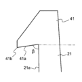
- FIG. 16A is a diagram illustrating a configuration of the claw portion 41 in the mounting structure 20 of Modification 1 of the above embodiment.
- the claw portion 41 of the first modification has a lower surface 41a of the claw portion 41 and a surface 21a of the flexible portion 21 (specifically, the surface of the flexible portion 21 when viewed from the side.
- the surface ⁇ faces the side where the lower surface 22a exists, and the angle ⁇ formed with the side surface connected to the lower surface 22a is an acute angle.
- the lower surface 22a of the claw portion 22 is a surface inclined in the negative direction of the Z axis (the direction opposite to the direction of the arrow) with respect to the X axis shown in FIG. It can also be said.
- the lower surface 22a of the claw portion 22 is a surface inclined downward with respect to the flexible direction of the flexible portion 21 described above.
- claw part 41 of the structure shown to FIG. 16A is used, even if the downward force is added with respect to the flexible part 21 and the nail
- FIG. 16B is a diagram illustrating a configuration of the main body 42 in the mounting structure 20 according to the second modification of the embodiment.
- the main body portion 42 of Modification 2 has an inclined portion 42 a in the vicinity of the edge of the first insertion hole 33. That is, in this modification, an example in which the inclined portion (lower surface 22a) is not provided on the claw portion side as shown in FIG. 8A but on the main body portion 42 side is shown.
- Fig. 16B shows an example in which the claw portion 41 according to the first modification shown in Fig. 16A is combined with the second member 20b having the inclined portion 42a.
- the tip portion 41b of the claw portion 41 and the inclined portion 42a are in contact with each other, and the tip portion 41b slides on the slope of the inclined portion 42b by the forward force caused by the bending of the flexible portion 21. .
- a force for moving the claw portion 41 forward by the inclined portion 42a works while realizing a mounting structure having a high strength against the pulling force, and the claw portion 41 is applied to the second member 20b. The amount is increased.
- the first opening region 33a and the second opening region 33b are both formed in a rectangular shape, but the first side 32a is common because both the opening regions 33a and 33b are adjacent to each other.
- these shapes are not particularly limited. That is, the shape of the first opening region 33a does not have to be rectangular, but may be any size and shape that allows the claw portion 22 to pass.
- the form of the fourth side 32c is not particularly limited with respect to the second opening region 33b.
- the attachment part 23 is in contact with both the 1st edge
- it may contact only the first side 32a. Further, it may not be sandwiched between the first side 32a and the second side 32b.
- the corner on the rear side of the attachment portion 23 is in contact with the second side 32b in a state where the first member 20a is attached to the second member 20b, but depending on the shape of the attachment portion 23, Other parts may be in contact with the second side 32b.
- the flexible part 21 becomes a shape where the flexibility of the direction along a Y-axis is low compared with the flexibility of the direction along an X-axis, it is not limited to this, The same flexibility or the direction along the Y-axis can be increased.
- the shapes of the first member 20a and the second member 20b and the shapes of the first insertion hole 33 and the second insertion hole 35 are not particularly limited.
- the attachment structure 20 is provided on both the connecting portion between the rod-like flexible portion 185a and the key-side support portion 183 of the key 100 and the connecting portion between the rod-like flexible portion 185a and the frame-side support portion 585 of the frame 500. Is provided. However, for any one of the coupling portions, a different attachment method may be adopted instead of the attachment structure 20. Moreover, in the said embodiment, the example which uses the attachment structure 20 in the keyboard apparatus 1 is shown. However, the mounting structure 20 can be used for devices other than the keyboard device 1. For example, the attachment structure 20 may be used to attach a printed wiring board to an equipment device or the like.
Landscapes
- Engineering & Computer Science (AREA)
- General Engineering & Computer Science (AREA)
- Physics & Mathematics (AREA)
- Acoustics & Sound (AREA)
- Multimedia (AREA)
- Mechanical Engineering (AREA)
- Electrophonic Musical Instruments (AREA)
Abstract
La présente invention concerne une structure de montage qui comprend : un premier élément qui comprend une partie de montage ayant une partie souple et une partie de crochet disposée sur une extrémité de la partie souple ; et un second élément qui comprend un trou d'insertion comportant, vu de dessus, une première région d'ouverture ayant une taille telle que la partie de crochet peut passer à travers, et une seconde région d'ouverture ayant une taille telle que la partie de crochet ne peut pas passer à travers. La seconde région d'ouverture a un premier côté partagé avec la première région d'ouverture, et un second côté positionné de manière à être diagonalement opposé au premier côté.
Applications Claiming Priority (2)
| Application Number | Priority Date | Filing Date | Title |
|---|---|---|---|
| JP2016-061670 | 2016-03-25 | ||
| JP2016061670A JP2017173697A (ja) | 2016-03-25 | 2016-03-25 | 取付け構造 |
Publications (1)
| Publication Number | Publication Date |
|---|---|
| WO2017164128A1 true WO2017164128A1 (fr) | 2017-09-28 |
Family
ID=59899435
Family Applications (1)
| Application Number | Title | Priority Date | Filing Date |
|---|---|---|---|
| PCT/JP2017/010969 Ceased WO2017164128A1 (fr) | 2016-03-25 | 2017-03-17 | Structure de montage |
Country Status (2)
| Country | Link |
|---|---|
| JP (1) | JP2017173697A (fr) |
| WO (1) | WO2017164128A1 (fr) |
Citations (6)
| Publication number | Priority date | Publication date | Assignee | Title |
|---|---|---|---|---|
| JPS53113969U (fr) * | 1977-02-18 | 1978-09-11 | ||
| JPH01136045U (fr) * | 1988-03-08 | 1989-09-18 | ||
| JPH01176987U (fr) * | 1988-05-31 | 1989-12-18 | ||
| JPH03108295U (fr) * | 1990-02-23 | 1991-11-07 | ||
| FR2761651A1 (fr) * | 1997-04-08 | 1998-10-09 | Peugeot | Dispositif de fixation d'un pare-chocs sur la caisse d'un vehicule automobile |
| US20090261619A1 (en) * | 2008-04-22 | 2009-10-22 | Dr. Ing. H.C.F. Porsche Aktiengesellschaft | Air-directing component and body front end of a motor vehicle |
-
2016
- 2016-03-25 JP JP2016061670A patent/JP2017173697A/ja active Pending
-
2017
- 2017-03-17 WO PCT/JP2017/010969 patent/WO2017164128A1/fr not_active Ceased
Patent Citations (6)
| Publication number | Priority date | Publication date | Assignee | Title |
|---|---|---|---|---|
| JPS53113969U (fr) * | 1977-02-18 | 1978-09-11 | ||
| JPH01136045U (fr) * | 1988-03-08 | 1989-09-18 | ||
| JPH01176987U (fr) * | 1988-05-31 | 1989-12-18 | ||
| JPH03108295U (fr) * | 1990-02-23 | 1991-11-07 | ||
| FR2761651A1 (fr) * | 1997-04-08 | 1998-10-09 | Peugeot | Dispositif de fixation d'un pare-chocs sur la caisse d'un vehicule automobile |
| US20090261619A1 (en) * | 2008-04-22 | 2009-10-22 | Dr. Ing. H.C.F. Porsche Aktiengesellschaft | Air-directing component and body front end of a motor vehicle |
Also Published As
| Publication number | Publication date |
|---|---|
| JP2017173697A (ja) | 2017-09-28 |
Similar Documents
| Publication | Publication Date | Title |
|---|---|---|
| US10339909B2 (en) | Electronic musical instrument, keyboard apparatus and frame | |
| US10657939B2 (en) | Keyboard apparatus and electronic keyboard instrument | |
| JP7172085B2 (ja) | 鍵盤装置 | |
| WO2018173923A1 (fr) | Dispositif de commutation et dispositif de clavier | |
| WO2018079668A1 (fr) | Dispositif de clavier | |
| WO2017164308A1 (fr) | Structure de montage | |
| WO2017164307A1 (fr) | Structure de montage | |
| US10636394B2 (en) | Hammer assembly, keyboard instrument, and hammer | |
| WO2017164310A1 (fr) | Structure de montage | |
| WO2018169080A1 (fr) | Dispositif de clavier | |
| WO2017164128A1 (fr) | Structure de montage | |
| WO2017163947A1 (fr) | Structure de montage | |
| US10825427B2 (en) | Hammer assembly and keyboard instrument | |
| CN116486767A (zh) | 键盘单元 | |
| WO2018047579A1 (fr) | Structure de fixation | |
| JPWO2018169077A1 (ja) | 鍵盤装置 | |
| WO2018173926A1 (fr) | Élément rotatif et dispositif de clavier | |
| JP2018017798A (ja) | 取付け構造 | |
| JP2018081137A (ja) | 鍵盤装置 | |
| WO2018131604A1 (fr) | Dispositif de clavier | |
| JP2018180069A (ja) | 電子楽器 | |
| JP2018180070A (ja) | 電子機器 | |
| JP2018163191A (ja) | ハンマアセンブリおよび鍵盤装置 | |
| JP2018180073A (ja) | 構造体及び電子楽器 | |
| JP2009042381A (ja) | 電子楽器用鍵盤装置 |
Legal Events
| Date | Code | Title | Description |
|---|---|---|---|
| NENP | Non-entry into the national phase |
Ref country code: DE |
|
| 121 | Ep: the epo has been informed by wipo that ep was designated in this application |
Ref document number: 17770170 Country of ref document: EP Kind code of ref document: A1 |
|
| 122 | Ep: pct application non-entry in european phase |
Ref document number: 17770170 Country of ref document: EP Kind code of ref document: A1 |