WO2017164423A1 - Machine de moulage par injection - Google Patents
Machine de moulage par injection Download PDFInfo
- Publication number
- WO2017164423A1 WO2017164423A1 PCT/JP2017/012489 JP2017012489W WO2017164423A1 WO 2017164423 A1 WO2017164423 A1 WO 2017164423A1 JP 2017012489 W JP2017012489 W JP 2017012489W WO 2017164423 A1 WO2017164423 A1 WO 2017164423A1
- Authority
- WO
- WIPO (PCT)
- Prior art keywords
- mold
- toggle support
- thickness adjusting
- adjusting motor
- control device
- Prior art date
- Legal status (The legal status is an assumption and is not a legal conclusion. Google has not performed a legal analysis and makes no representation as to the accuracy of the status listed.)
- Ceased
Links
Images



Classifications
-
- B—PERFORMING OPERATIONS; TRANSPORTING
- B22—CASTING; POWDER METALLURGY
- B22D—CASTING OF METALS; CASTING OF OTHER SUBSTANCES BY THE SAME PROCESSES OR DEVICES
- B22D17/00—Pressure die casting or injection die casting, i.e. casting in which the metal is forced into a mould under high pressure
- B22D17/20—Accessories: Details
- B22D17/26—Mechanisms or devices for locking or opening dies
-
- B—PERFORMING OPERATIONS; TRANSPORTING
- B29—WORKING OF PLASTICS; WORKING OF SUBSTANCES IN A PLASTIC STATE IN GENERAL
- B29C—SHAPING OR JOINING OF PLASTICS; SHAPING OF MATERIAL IN A PLASTIC STATE, NOT OTHERWISE PROVIDED FOR; AFTER-TREATMENT OF THE SHAPED PRODUCTS, e.g. REPAIRING
- B29C45/00—Injection moulding, i.e. forcing the required volume of moulding material through a nozzle into a closed mould; Apparatus therefor
- B29C45/17—Component parts, details or accessories; Auxiliary operations
- B29C45/64—Mould opening, closing or clamping devices
- B29C45/66—Mould opening, closing or clamping devices mechanical
-
- B—PERFORMING OPERATIONS; TRANSPORTING
- B29—WORKING OF PLASTICS; WORKING OF SUBSTANCES IN A PLASTIC STATE IN GENERAL
- B29C—SHAPING OR JOINING OF PLASTICS; SHAPING OF MATERIAL IN A PLASTIC STATE, NOT OTHERWISE PROVIDED FOR; AFTER-TREATMENT OF THE SHAPED PRODUCTS, e.g. REPAIRING
- B29C45/00—Injection moulding, i.e. forcing the required volume of moulding material through a nozzle into a closed mould; Apparatus therefor
- B29C45/17—Component parts, details or accessories; Auxiliary operations
- B29C45/76—Measuring, controlling or regulating
Definitions
- the present invention relates to an injection molding machine.
- the injection molding machine described in Patent Document 1 drives the mold thickness adjusting motor to advance the toggle support together with the movable platen in the mold closing direction, and monitors the detection value from the mold clamping force sensor. When the detected value reaches the threshold value, it is determined that the mold touch has been performed, the driving of the mold thickness adjusting motor is stopped, and the forward movement of the toggle support is stopped.
- the mold thickness adjusting motor cannot be stopped suddenly due to inertia. For this reason, the toggle support is displaced from the target position, and the accuracy of mold thickness adjustment is poor.
- the present invention has been made in view of the above problems, and has as its main object to provide an injection molding machine with improved accuracy of mold thickness adjustment.
- a mold mounting board to which one of a fixed mold and a movable mold is mounted a connecting board connected to the mold mounting board at an interval in the mold opening / closing direction, and adjusting the distance to adjust the mold thickness.
- a mold thickness adjusting mechanism to perform, and a control device for controlling the mold thickness adjusting mechanism includes: a screw shaft formed on a rod that connects the mold mounting plate and the connecting plate; a screw nut held on one of the mold mounting plate and the connecting plate; A mold thickness adjusting motor for rotating one of the screw shaft and the screw nut to be combined,
- the control device detects a mold touch that touches the movable mold and the fixed mold while the mold thickness adjusting motor is being driven, and the detection of the mold touch until the mold thickness adjusting motor stops driving.
- An injection molding machine is provided that detects gap deviation.
- an injection molding machine with improved accuracy of mold thickness adjustment is provided.
- FIG. 1 is a diagram illustrating a state when mold opening of an injection molding machine according to an embodiment is completed.
- FIG. 2 is a diagram illustrating a state during mold clamping of the injection molding machine according to the embodiment.
- the injection molding machine includes a frame Fr, a mold clamping device 10, an injection device 40, an ejector device 50, and a control device 90.
- the moving direction of the movable platen 13 when the mold is closed (right direction in FIGS. 1 and 2) is the front, and the moving direction of the movable platen 13 when the mold is opened (left direction in FIGS. 1 and 2). This will be described as the rear.
- the mold clamping apparatus 10 performs mold closing, mold clamping, and mold opening of the mold apparatus 30.
- the mold clamping device 10 is a horizontal mold whose mold opening and closing direction is a horizontal direction.
- the mold clamping device 10 includes a fixed platen 12, a movable platen 13, a toggle support 15, a tie bar 16, a toggle mechanism 20, a mold clamping motor 25, and a motion conversion mechanism 26.
- the fixed platen 12 is fixed to the frame Fr.
- a fixed mold 32 is attached to a surface of the fixed platen 12 facing the movable platen 13.
- the movable platen 13 is movable along a guide (for example, guide rail) 17 laid on the frame Fr, and is movable forward and backward with respect to the fixed platen 12.
- a movable mold 33 is attached to the surface of the movable platen 13 facing the fixed platen 12.
- the mold is closed, clamped, and opened by moving the movable platen 13 back and forth with respect to the fixed platen 12.
- the fixed mold 32 and the movable mold 33 constitute a mold apparatus 30.
- the toggle support 15 is connected to the fixed platen 12 with an interval L, and is placed on the frame Fr so as to be movable in the mold opening / closing direction.
- the toggle support 15 may be movable along a guide laid on the frame Fr.
- the guide of the toggle support 15 may be the same as the guide 17 of the movable platen 13.
- the fixed platen 12 is fixed to the frame Fr and the toggle support 15 is movable in the mold opening / closing direction with respect to the frame Fr.
- the toggle support 15 is fixed to the frame Fr and fixed to the fixed platen. 12 may be movable in the mold opening / closing direction with respect to the frame Fr.
- the tie bar 16 connects the fixed platen 12 and the toggle support 15 with an interval L therebetween.
- a plurality of (for example, four) tie bars 16 may be used.
- Each tie bar 16 is parallel to the mold opening / closing direction and extends in accordance with the mold clamping force.
- At least one tie bar 16 is provided with a mold clamping force detector 18.
- the mold clamping force detector 18 detects the mold clamping force by detecting distortion of the tie bar 16 and sends a signal indicating the detection result to the control device 90.
- the clamping force detector 18 is not limited to the strain gauge type, but may be a piezoelectric type, a capacitive type, a hydraulic type, an electromagnetic type, or the like, and the mounting position thereof is not limited to the tie bar 16.
- the toggle mechanism 20 moves the movable platen 13 with respect to the fixed platen 12.
- the toggle mechanism 20 is disposed between the movable platen 13 and the toggle support 15.
- the toggle mechanism 20 includes a cross head 21 and a pair of link groups. Each link group includes a first link 22 and a second link 23 that are connected to each other by a pin or the like.
- the first link 22 is swingably attached to the movable platen 13 with a pin or the like
- the second link 23 is swingably attached to the toggle support 15 with a pin or the like.
- the second link 23 is coupled to the crosshead 21 via the third link 24.
- the configuration of the toggle mechanism 20 is not limited to the configuration shown in FIGS.
- the number of nodes is five, but may be four, and one end portion of the third link 24 may be coupled to the node between the first link 22 and the second link 23. .
- the mold clamping motor 25 is attached to the toggle support 15 and operates the toggle mechanism 20.
- the mold clamping motor 25 advances and retracts the cross head 21 to bend and extend the first link 22 and the second link 23 and advance and retract the movable platen 13.
- the motion conversion mechanism 26 converts the rotational motion of the mold clamping motor 25 into the linear motion of the cross head 21.
- the motion conversion mechanism 26 includes a screw shaft and a screw nut that is screwed onto the screw shaft. A ball or a roller may be interposed between the screw shaft and the screw nut.
- the control device 90 includes a CPU (Central Processing Unit) 91, a storage medium 92 such as a memory, an input interface 93, and an output interface 94.
- the control device 90 performs various controls by causing the CPU 91 to execute a program stored in the storage medium 92. Further, the control device 90 receives a signal from the outside through the input interface 93 and transmits a signal through the output interface 94 to the outside.
- the control device 90 controls a mold closing process, a mold clamping process, a mold opening process, and the like.
- the mold clamping motor 25 is driven to advance the cross head 21 to the mold closing completion position at a set speed, thereby moving the movable platen 13 forward and causing the movable mold 33 to touch the fixed mold 32.
- the position and speed of the cross head 21 are detected using, for example, the encoder 25a of the mold clamping motor 25.
- the encoder 25 a detects the rotation of the mold clamping motor 25 and sends a signal indicating the detection result to the control device 90.
- a mold clamping force is generated by further driving the mold clamping motor 25 to further advance the cross head 21 from the mold closing completion position to the mold clamping position.
- a cavity space 34 is formed between the movable mold 33 and the fixed mold 32 during mold clamping, and the injection device 40 fills the cavity space 34 with a liquid molding material.
- a molded product is obtained by solidifying the filled molding material.
- a plurality of cavity spaces 34 may be provided, and in this case, a plurality of molded products can be obtained simultaneously.
- the mold clamping motor 25 is driven to retract the cross head 21 to the mold opening completion position at a set speed, thereby retracting the movable platen 13 and separating the movable mold 33 from the fixed mold 32. Thereafter, the ejector device 50 projects the molded product from the movable mold 33.
- the toggle mechanism 20 amplifies the driving force of the mold clamping motor 25 and transmits it to the movable platen 13.
- the amplification magnification is also called toggle magnification.
- the toggle magnification changes according to an angle ⁇ formed by the first link 22 and the second link 23 (hereinafter also referred to as “link angle ⁇ ”).
- the link angle ⁇ is obtained from the position of the cross head 21. When the link angle ⁇ is 180 °, the toggle magnification is maximized.
- the mold thickness adjustment is performed so that a predetermined mold clamping force can be obtained at the time of mold clamping.
- the distance L between the fixed platen 12 and the toggle support 15 is set so that the link angle ⁇ of the toggle mechanism 20 becomes a predetermined angle when the movable mold 33 touches the fixed mold 32. Adjust.
- the mold clamping device 10 includes a mold thickness adjustment mechanism 60 that performs mold thickness adjustment by adjusting the distance L between the fixed platen 12 and the toggle support 15.
- the mold thickness adjusting mechanism 60 rotates a screw shaft 61 formed at the rear end portion of the tie bar 16, a screw nut 62 that is rotatably held by the toggle support 15, and a screw nut 62 that is screwed onto the screw shaft 61.
- a mold thickness adjusting motor 63 is a mold thickness adjusting motor 63.
- the screw shaft 61 and the screw nut 62 are provided for each tie bar 16.
- the rotation of the mold thickness adjusting motor 63 may be transmitted to a plurality of screw nuts 62 via a rotation transmitting unit 64 constituted by a belt, a pulley or the like.
- the plurality of screw nuts 62 can be rotated synchronously. It should be noted that the plurality of screw nuts 62 can be individually rotated by changing the transmission path of the rotation transmission unit 64.
- the rotation transmission part 64 may be comprised with a gear etc. instead of a belt, a pulley, etc.
- a passive gear is formed on the outer periphery of each screw nut 62
- a drive gear is attached to the output shaft of the mold thickness adjusting motor 63
- a plurality of passive gears and an intermediate gear that meshes with the drive gear are in the central portion of the toggle support 15. It is held rotatably.
- the operation of the mold thickness adjusting mechanism 60 is controlled by the control device 90.
- the control device 90 drives the mold thickness adjusting motor 63 to rotate the screw nut 62, thereby adjusting the position of the toggle support 15 that holds the screw nut 62 rotatably with respect to the fixed platen 12.
- the interval L with the toggle support 15 is adjusted.
- the screw nut 62 is rotatably held with respect to the toggle support 15 and the tie bar 16 on which the screw shaft 61 is formed is fixed to the fixed platen 12, but the present invention is not limited to this.
- the screw nut 62 may be rotatably held with respect to the fixed platen 12, and the tie bar 16 may be fixed with respect to the toggle support 15.
- the interval L can be adjusted by rotating the screw nut 62.
- the screw nut 62 may be fixed to the toggle support 15 and the tie bar 16 may be held rotatably with respect to the fixed platen 12. In this case, the interval L can be adjusted by rotating the tie bar 16.
- the screw nut 62 may be fixed to the fixed platen 12 and the tie bar 16 may be held rotatably with respect to the toggle support 15. In this case, the interval L can be adjusted by rotating the tie bar 16.
- the mold thickness adjusting mechanism 60 adjusts the distance L by rotating one of the screw shaft 61 and the screw nut 62 that are screwed together.
- a plurality of mold thickness adjusting mechanisms 60 may be used, and a plurality of mold thickness adjusting motors 63 may be used.
- the fixed platen 12 corresponds to the die mounting plate described in the claims
- the toggle support 15 corresponds to the connecting plate described in the claims
- the tie bar 16 corresponds to the rod described in the claims.
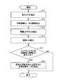
- FIG. 3 shows a flowchart of the mold thickness adjustment process of the control device according to the embodiment.
- the mold thickness adjustment process by the control device 90 is started when the thickness of the mold apparatus 30 changes due to the replacement of the mold apparatus 30 or the temperature change of the mold apparatus 30.
- control device 90 drives the mold thickness adjusting motor 63 in a state where the link angle ⁇ of the toggle mechanism 20 is set to a predetermined angle and the mold clamping motor 25 is stopped, and the movable mold 33 is fixed to the fixed mold 32 during the driving.
- a type touch for touching is detected (step S11).
- An interval L between the fixed platen 12 and the toggle support 15 at the time when the mold touch is detected is set as a target interval L0 (see FIGS. 4 and 5).
- the mold thickness adjusting motor 63 is driven to advance the toggle support 15 from the state in which the movable mold 33 is separated from the fixed mold 32, and the movable platen 13 connected to the toggle support 15 is advanced. To be done. That is, the detection of the mold touch is performed by closing the mold device 30.
- the control device 90 monitors the mold clamping force while the mold thickness adjusting motor 63 is being driven, and detects a mold touch based on the mold clamping force. For example, the control device 90 may determine that the mold touch has been performed when the detection value of the mold clamping force detector 18 reaches a threshold value. For this determination, time differentiation of the detection value of the mold clamping force detector 18 may be used.
- the control device 90 may monitor the torque of the mold thickness adjusting motor 63 while the mold thickness adjusting motor 63 is being driven, and detect the mold touch based on the torque.
- the control device 90 may determine that the type touch has been performed when the detection value of the torque detector 65 reaches a threshold value. For the determination, time differentiation of the detection value of the torque detector 65 may be used.
- the torque detector 65 for example, a current detector that detects the current of the mold thickness adjusting motor 63 is used.
- the control device 90 detects the mold touch by closing the mold device 30 with the mold thickness adjusting motor 63, but detects the mold touch by depressurizing the mold device 30 with the mold thickness adjusting motor 63. May be.
- the depressurization of the mold apparatus 30 is performed from the mold clamping state.
- the detection value of the mold clamping force detector 18 reaches a threshold value, it may be determined that the state of the mold apparatus 30 has returned to the state of mold touch.
- the detection value of the torque detector 65 reaches the threshold value, it may be determined that the state of the mold apparatus 30 has returned to the state of the mold touch.
- Only one of the mold clamping force detector 18 and the torque detector 65 may be used for detecting the mold touch, or both of them may be used.
- the control device 90 stops driving the mold thickness adjusting motor 63 when detecting the mold touch (step S12). Since the mold thickness adjusting motor 63 cannot be stopped suddenly due to inertia, the distance L between the fixed platen 12 and the toggle support 15 deviates from the target distance L0. For example, when the drive of the mold thickness adjusting motor 63 is stopped while the toggle support 15 is moving forward, the distance L between the fixed platen 12 and the toggle support 15 becomes narrower than the target distance L0. Further, when the drive of the mold thickness adjusting motor 63 is stopped while the toggle support 15 is retracted, the distance L between the fixed platen 12 and the toggle support 15 becomes wider than the target distance L0.
- the control device 90 detects the deviation of the interval L from the detection of the mold touch to the stop of the driving of the mold thickness adjusting motor 63 (step S13).
- the deviation of the interval L is detected using, for example, the encoder 63a of the mold thickness adjusting motor 63.
- the encoder 63 a detects the rotation angle, rotation speed, rotation direction, and the like of the mold thickness adjustment motor 63 and sends a signal indicating the detection result to the control device 90.
- the control device 90 corrects the interval L based on the detected deviation of the interval L (step S14). For example, the control device 90 returns the interval L to the target interval L0 by rotating the mold thickness adjusting motor 63 in the direction opposite to that at the time of detecting the mold touch. Therefore, the accuracy of mold thickness adjustment can be improved, and a predetermined mold clamping force can be obtained during mold clamping. In addition, it is possible to appropriately set a depressurization position for moving the crosshead 21 in an emergency. The pressure acting on the mold apparatus 30 in an emergency can be sufficiently reduced, and the mold opening of the mold apparatus 30 can be suppressed. This is particularly effective when the mold apparatus 30 includes a movable core.
- the correction of the interval L may be performed only when the amount of deviation (the magnitude of deviation) of the interval L from the target interval L0 is a predetermined amount or more.
- the deviation amount can be expressed by the rotation angle of the mold thickness adjusting motor 63.
- the control device 90 of the present embodiment returns the distance L between the fixed platen 12 and the toggle support 15 to the target distance L0 by the reverse rotation of the mold thickness adjusting motor 63, but before the distance L returns to the target distance L0.
- the reverse rotation may be stopped or the reverse rotation may be stopped after the interval L has passed the target interval L0.
- the amount of deviation of the interval L from the target interval L0 may be smaller than before the reverse rotation.
- the mold thickness adjusting motor 63 when the mold thickness adjusting motor 63 is rotated in the opposite direction to that at the time of detecting the mold touch, and further when the mold thickness adjusting motor 63 is rotated in the same direction as that at the time of detecting the mold touch, the above interval is used.
- the reverse rotation may be stopped after L has passed the target interval L0 for a while. This is because an operation for making the interval L close to the target interval L0 is possible thereafter.
- the control device 90 may determine whether or not the interval L changes during mold clamping due to backlash of the mold thickness adjusting mechanism 60 based on the immediately preceding rotation direction of the mold thickness adjusting motor 63 (step S15).
- the backlash of the mold thickness adjusting mechanism 60 is, for example, play between the screw shaft 61 and the screw nut 62, play between gears constituting the rotation transmitting unit 64, and the like.
- the reaction force of the mold clamping force acts on the screw nut 62.
- the reaction force acts in a direction in which the movable mold 33 and the fixed mold 32 are separated from each other.
- the immediately preceding rotation direction of the mold thickness adjusting motor 63 is a direction in which the movable mold 33 and the fixed mold 32 are separated from each other, it is determined that the interval L does not change during mold clamping due to backlash of the mold thickness adjusting mechanism 60. .
- the immediately preceding rotation direction of the mold thickness adjusting motor 63 is a direction in which the movable mold 33 and the fixed mold 32 are brought close to each other, it is determined that the interval L changes during mold clamping due to backlash of the mold thickness adjusting mechanism 60.
- the controller 90 determines that the interval L changes during mold clamping due to backlash of the mold thickness adjusting mechanism 60 based on the rotation direction of the immediately preceding mold thickness adjusting motor 63, the mold thickness adjustment is performed in the direction opposite to the immediately preceding rotation direction.
- the motor 63 is rotated (step S16).
- the amount of rotation may be a degree corresponding to backlash. It is possible to prevent an impact due to backlash of the mold thickness adjusting mechanism 60 during mold clamping.
- control device 90 determines whether or not the interval L changes during mold clamping due to backlash of the mold thickness adjusting mechanism 60 based on the rotation direction of the mold thickness adjusting motor 63 when the interval L is corrected. If the controller 90 determines that the interval L changes during mold clamping, the controller 90 may then rotate the mold thickness adjustment motor 63 in the same direction as when a mold touch is detected. The amount of rotation may be a degree corresponding to backlash.
- step S14 the interval L described in step S14 is corrected before the determination described in step S15, but the present invention is not limited to this.
- the control device 90 may skip step S13 and step S14 and proceed to step S15.
- step S15 the control device 90 determines whether or not the interval L changes during mold clamping due to backlash of the mold thickness adjusting mechanism 60 based on the rotation direction of the mold thickness adjusting motor 63 at the time of detecting the mold touch. Judging.
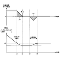
- FIG. 4 is a diagram illustrating a temporal change in the rotational speed of the mold thickness adjusting motor and a temporal change in the interval L when the mold thickness adjustment is performed by moving the toggle support forward from the mold open state according to the embodiment.
- the positive rotation speed of the mold thickness adjusting motor means that the rotation direction is the direction in which the toggle support is advanced.
- the negative rotation speed of the mold thickness adjusting motor means that the rotation direction is the direction in which the toggle support is retracted.
- the controller 90 sets the mold thickness adjustment motor 63 in a state where the link angle ⁇ of the toggle mechanism 20 is set to a predetermined angle and the mold clamping motor 25 is stopped. To drive. By moving the toggle support 15 forward by the mold thickness adjusting motor 63 from the mold open state, the movable platen 13 can be advanced and the mold can be closed.
- the control device 90 detects a mold touch in which the movable mold 33 touches the fixed mold 32 at time t1 (step S11 in FIG. 3). As described above, the mold clamping force detector 18 and the torque detector 65 of the mold thickness adjusting motor 63 are used for detecting the mold touch.
- the control device 90 stores the interval L between the fixed platen 12 and the toggle support 15 at the time when the mold touch is detected as the target interval L0. That is, the control device 90 stores the position of the toggle support 15 at the time when the mold touch is detected as the target position.
- the toggle support position detector for detecting the position of the toggle support for example, an encoder 63a of the mold thickness adjusting motor 63, a linear encoder, a laser displacement meter, or the like is used.
- the control device 90 stops driving the mold thickness adjusting motor 63 when detecting the mold touch at time t1 (step S12 in FIG. 3). Since the mold thickness adjusting motor 63 cannot be stopped suddenly due to inertia, the interval L between the toggle support 15 and the fixed platen 12 is stopped by the time t2 when the mold thickness adjusting motor 63 stops and the toggle support 15 stops. Becomes smaller than the target interval L0.
- the accuracy of the mold thickness adjustment was poor, and the accuracy of the mold clamping force obtained at the time of mold clamping was poor.
- the accuracy of the depressurization position for moving the crosshead 21 in an emergency is poor, and it has been difficult to sufficiently reduce the pressure acting on the mold apparatus 30 and to prevent the mold apparatus 30 from opening.
- the control device 90 of the present embodiment detects a shift in the interval L from the detection of the type touch (time t1) to the stop of the toggle support 15 (time t2) (step S13 in FIG. 3).
- the deviation of the interval L is proportional to the time integral value A1 of the rotational speed of the mold thickness adjusting motor 63 from time t1 to time t2. Therefore, the deviation of the interval L may be expressed by a time integration value A1.
- the control device 90 corrects the interval L based on the detected deviation of the interval L (step S14 in FIG. 3). For example, the control device 90 rotates the mold thickness adjusting motor 63 in the direction opposite to that at the time of detecting the mold touch from time t3 to time t4 to retract the toggle support 15. Thereby, the position of the toggle support 15 can be corrected, and the interval L can be corrected.
- the time integral value A2 of the rotational speed of the mold thickness adjusting motor 63 from time t3 to time t4 is opposite in sign to the time integral value A1 of the rotational speed of the mold thickness adjusting motor 63 from time t1 to time t2.
- the size may be the same.
- the accuracy of mold thickness adjustment can be improved, and a predetermined mold clamping force can be obtained at the time of mold clamping by the mold clamping motor 25.
- the pressure acting on the mold apparatus 30 in an emergency can be sufficiently reduced, and the mold opening of the mold apparatus 30 can be suppressed. This is particularly effective when the mold apparatus 30 includes a movable core.
- the correction of the interval L may be performed only when the deviation amount of the interval L from the target interval L0 is a predetermined amount or more. Further, it is sufficient that the amount of deviation of the interval L from the target interval L0 is smaller after the interval L is corrected than before the interval L is corrected, and the interval L may not be accurately returned to the target interval L0.
- the control device 90 finishes the mold thickness adjustment process. After the mold thickness adjustment process, the interval L does not change during mold clamping by the mold clamping motor 25 due to backlash between the screw nut 62 and the screw shaft 61. Therefore, the reverse rotation of the mold thickness adjusting motor 63 is unnecessary.
- the magnitude of the deviation between the interval L and the target interval L0 at the end of the mold thickness adjustment process is zero in FIG. 4, but when the toggle support 15 is stopped immediately after the mold touch detection (time t2). It is only necessary to be smaller than the magnitude of the deviation between the interval L and the target interval L0. Compared with the case where the mold thickness adjustment process is finished at time t2, the accuracy of mold thickness adjustment can be improved, and a predetermined mold clamping force can be obtained when the mold clamping motor 25 performs mold clamping. In addition, it is possible to appropriately set a depressurization position for moving the crosshead 21 in an emergency. The pressure acting on the mold apparatus 30 in an emergency can be sufficiently reduced, and the mold opening of the mold apparatus 30 can be suppressed. This is particularly effective when the mold apparatus 30 includes a movable core.
- FIG. 5 is a diagram illustrating a temporal change in the rotational speed of the mold thickness adjusting motor and a temporal change in the interval L when the mold thickness adjustment is performed by retracting the toggle support from the mold clamping state according to the embodiment.
- the positive rotation speed of the mold thickness adjusting motor means that the rotation direction is the direction in which the toggle support is advanced.
- the negative rotation speed of the mold thickness adjusting motor means that the rotation direction is the direction in which the toggle support is retracted.
- the control device 90 When performing the mold thickness adjustment by retracting the toggle support from the mold clamping state, the control device 90 sets the mold thickness adjusting motor 63 in a state where the link angle ⁇ of the toggle mechanism 20 is set to a predetermined angle and the mold clamping motor 25 is stopped. To drive. The movable platen 13 can be moved backward by retracting the toggle support 15 by the mold thickness adjusting motor 63 from the mold clamping state, and the mold apparatus 30 can be depressurized.
- the control device 90 detects the completion of depressurization in which the movable mold 33 is separated from the fixed mold 32 from the mold-clamping state as a mold touch in which the movable mold 33 touches the fixed mold 32 from the mold open state. (Step S11 in FIG. 3).
- the mold clamping force detector 18, the torque detector 65 of the mold thickness adjusting motor 63, and the like are used to detect the completion of the depressurization of the mold apparatus 30.
- the control device 90 stores the interval L between the fixed platen 12 and the toggle support 15 at the time when the depressurization completion is detected as the target interval L0. That is, the control device 90 stores the position of the toggle support 15 at the time when the depressurization completion is detected as the target position.
- the toggle support position detector for detecting the position of the toggle support for example, an encoder 63a of the mold thickness adjusting motor 63, a linear encoder, a laser displacement meter, or the like is used.
- the controller 90 detects the completion of the depressurization at time t1, the controller 90 stops driving the mold thickness adjusting motor 63 (step S12 in FIG. 3). Since the mold thickness adjusting motor 63 cannot be stopped suddenly due to inertia, the interval L between the toggle support 15 and the fixed platen 12 is stopped by the time t2 when the mold thickness adjusting motor 63 stops and the toggle support 15 stops. Becomes larger than the target interval L0.
- the control device 90 of the present embodiment detects a shift in the interval L from the detection of the type touch (time t1) to the stop of the toggle support 15 (time t2) (step S13 in FIG. 3).
- the deviation of the interval L is proportional to the time integral value A1 of the rotational speed of the mold thickness adjusting motor 63 from time t1 to time t2. Therefore, the deviation of the interval L may be expressed by a time integration value A1.
- the control device 90 corrects the interval L based on the detected deviation of the interval L (step S14 in FIG. 3). For example, from time t3 to time t4, the control device 90 rotates the mold thickness adjusting motor 63 in the direction opposite to that at the time of detecting the mold touch, thereby moving the toggle support 15 forward. Thereby, the position of the toggle support 15 can be corrected, and the interval L can be corrected.
- the time integral value A2 of the rotational speed of the mold thickness adjusting motor 63 from time t3 to time t4 is opposite in sign to the time integral value A1 of the rotational speed of the mold thickness adjusting motor 63 from time t1 to time t2.
- the size may be the same.
- the accuracy of mold thickness adjustment can be improved, and a predetermined mold clamping force can be obtained at the time of mold clamping by the mold clamping motor 25.
- the correction of the interval L may be performed only when the deviation amount of the interval L from the target interval L0 is a predetermined amount or more. Further, it is sufficient that the amount of deviation of the interval L from the target interval L0 is smaller after the interval L is corrected than before the interval L is corrected, and the interval L may not be accurately returned to the target interval L0.
- control device 90 rotates the mold thickness adjusting motor 63 from the time t5 to the time t6 in the direction opposite to the previous rotation direction (step S16 in FIG. 3).
- the amount of rotation may correspond to backlash, and the position of the toggle support 15 may remain stopped from time t5 to time t6 as shown in FIG. Impact due to backlash of the mold thickness adjusting mechanism 60 can be prevented during mold clamping.
- the rotation amount corresponding to the backlash is read in advance from the storage medium 92 and used. Note that when the rotation corresponding to the backlash is performed, the torque of the mold thickness adjusting motor 63 increases. For this reason, the torque detector 65 may monitor the torque of the mold thickness adjusting motor 63 to rotate the rotation amount corresponding to the backlash.
- the position of the toggle support 15 is not displaced in FIG. 5, but the position of the toggle support 15 may be displaced.
- the magnitude of the deviation between the interval L and the target interval L0 at the end of the mold thickness adjustment process indicates that the interval L and the target interval L0 when the toggle support 15 is stopped immediately after the mold touch detection (time t2). It only needs to be smaller than the magnitude of the deviation.
- the accuracy of mold thickness adjustment can be improved, and a predetermined mold clamping force can be obtained when the mold clamping motor 25 performs mold clamping.
- the toggle support 15 is advanced from time t3 to time t4 to reduce the interval L, and the interval L is returned to the target interval L0 at time t4 when the advancement of the toggle support 15 is stopped.
- L may be smaller than the target interval L0.
- the interval L may be returned to the target interval L0 at time t6 by retracting the toggle support 15 from time t5 to time t6 to increase the interval L.
- the following molding condition setting methods (1) to (5) and the following injection molding machines (6) to (10) are provided.
- a molding condition setting method for moving the toggle support to a predetermined position wherein the toggle support is moved to the predetermined position by moving the toggle support in a direction in which the fixed mold and the movable mold are separated from each other
- a molding condition setting method for completing the process of moving the toggle support to the predetermined position At the time of mold clamping, a force acts on the toggle support in a direction in which the fixed mold and the movable mold are separated from each other. Therefore, if the toggle support is moved to a predetermined position by moving the toggle support in a direction in which the fixed mold and the movable mold are separated from each other, and the processing for moving the toggle support to the predetermined position is completed, the toggle caused by backlash is performed during mold clamping. Misalignment of support can be suppressed.
- a force acts on the toggle support in a direction in which the fixed mold and the movable mold are separated from each other.
- the mold thickness adjusting motor is then moved in the direction in which the fixed mold and the movable mold are separated from each other.
- a toggle support that is moved in a predetermined direction, a mold touch detector that detects a mold touch between the fixed mold and the movable mold, and the toggle support when the mold touch is detected by the mold touch detector. And a control device for moving the toggle support in a direction opposite to the predetermined direction.
- the toggle support does not stop immediately after detecting the type touch due to inertia. Therefore, by moving the toggle support in the opposite direction, the toggle support can be brought close to the position at the time of mold touch detection, and the accuracy of the mold clamping force can be improved.
- the mold touch detector for example, a mold clamping force detector or a torque detector of a mold thickness adjusting motor is used.
- a toggle support that is moved to a predetermined position, and the toggle support is moved to the predetermined position by moving the toggle support in a direction in which the fixed mold and the movable mold are separated from each other.
- An injection molding machine having a control device for completing the movement process to the position.
- a force acts on the toggle support in a direction in which the fixed mold and the movable mold are separated from each other. Therefore, if the toggle support is moved to a predetermined position by moving the toggle support in a direction in which the fixed mold and the movable mold are separated from each other, and the processing for moving the toggle support to the predetermined position is completed, the toggle caused by backlash is performed during mold clamping. Misalignment of support can be suppressed.
- a mold thickness adjusting motor a toggle support moved by rotation of the mold thickness adjusting motor, and moving the toggle support in a direction in which the fixed mold and the movable mold approach each other, thereby moving the toggle support to a predetermined position.
- a control device for rotating the mold thickness adjusting motor in a direction in which the fixed mold and the movable mold are separated from each other.
- a force acts on the toggle support in a direction in which the fixed mold and the movable mold are separated from each other.
- the mold thickness adjusting motor is then moved in the direction in which the fixed mold and the movable mold are separated from each other.
- a motion conversion mechanism that converts a rotational motion of the mold thickness adjusting motor into a linear motion of the toggle support, and the control device rotates the mold thickness adjusting motor by a backlash amount of the motion converting mechanism.
- the toggle support moving process is not limited to the process of moving when detecting the mold touch in the mold thickness adjustment.
- the toggle support moving process includes all processes for moving the toggle support other than the above.
- the control device 90 of the above embodiment detects a deviation of the distance L between the toggle support 15 and the fixed platen 12 from the detection of the mold touch to the stop of the driving of the mold thickness adjusting motor 63 (step S13), and the detected deviation described above.
- the interval L is corrected based on (step S14), but the present invention is not limited to this.
- the control device may output an alarm when the deviation is greater than or equal to a threshold value. It is possible to detect machine failures.
- the mold clamping device 10 of the above embodiment is a horizontal mold whose horizontal direction is the mold opening / closing direction, but may be a vertical mold whose vertical direction is the mold opening / closing direction.
- the vertical mold clamping device has a lower platen, upper platen, toggle support, tie bar, toggle mechanism, mold clamping motor, mold thickness adjusting mechanism, and the like.
- One of the lower platen and the upper platen is used as a fixed platen, and the other is used as a movable platen.
- a lower mold is attached to the lower platen, and an upper mold is attached to the upper platen.
- the lower die and the upper die constitute a mold apparatus.
- the lower mold may be attached to the lower platen via a rotary table.
- the toggle support is disposed below the lower platen.
- the toggle mechanism is disposed between the toggle support and the lower platen.
- the tie bar is parallel to the vertical direction, passes through the lower platen, and connects the upper platen and the toggle support.
- the vertical mold thickness adjustment mechanism adjusts the mold thickness by adjusting the distance between the upper platen and the toggle support according to changes in the thickness of the mold apparatus.
- the interval between the upper platen and the toggle support is adjusted so that the link angle of the toggle mechanism becomes a predetermined angle at the time of mold touch when the lower mold and the upper mold touch.
- the link angle can be adjusted to a predetermined angle when mold closing is completed, and a predetermined mold clamping force can be obtained during mold clamping.
- the mold thickness adjusting mechanism includes a screw shaft formed on the tie bar, a screw nut held on one of the upper platen and the toggle support, and a mold thickness adjusting motor that rotates one of the screw shaft and the screw nut that are screwed together. Have.
- the mold thickness adjusting mechanism may further include a screw nut held on the other of the upper platen and the toggle support.
- the upper platen corresponds to the mold mounting plate described in the claims
- the toggle support corresponds to the connecting plate described in the claims
- the tie bar corresponds to the rod described in the claims.
- the mold clamping device 10 of the above embodiment has a toggle mechanism 20 and a mold clamping motor 25 that operates the toggle mechanism 20, but may have a linear motor for mold opening and closing and an electromagnet for mold clamping.
- the electromagnet type mold clamping device has, for example, a fixed platen, a movable platen, a rear platen, a tie bar, a suction plate, a rod, and a mold thickness adjusting mechanism.
- the rear platen is disposed on the side opposite to the stationary platen with respect to the movable platen (that is, behind the movable platen).
- the tie bar connects the fixed platen and the rear platen at an interval in the mold opening / closing direction.
- the suction plate can move forward and backward together with the movable platen behind the rear platen.
- the rod is inserted into the through hole of the rear platen and connects the movable platen and the suction plate.
- An electromagnet is formed on at least one of the rear platen and the attracting plate, and an attracting force by the electromagnet acts between the rear platen and the attracting plate to generate a clamping force.
- Electromagnet type mold thickness adjustment mechanism adjusts the mold thickness by adjusting the distance between the movable platen and the suction plate.
- the distance between the movable platen and the suction plate is adjusted so that a predetermined gap is formed between the suction plate and the rear platen at the time of the mold touch when the movable mold and the fixed mold touch.
- a predetermined gap can be formed between the suction plate and the rear platen when the mold closing is completed, and a predetermined mold clamping force can be obtained at the time of mold clamping.
- the mold thickness adjusting mechanism includes a screw shaft formed on the rod, a screw nut held on one of the movable platen and the suction plate, and a mold thickness adjusting motor that rotates one of the screw shaft and the screw nut that are screwed together.
- the mold thickness adjusting mechanism may further include a screw nut held on the other of the movable platen and the suction plate.
- the movable platen corresponds to the mold mounting plate described in the claims
- the suction plate corresponds to the connecting plate described in the claims.
Landscapes
- Engineering & Computer Science (AREA)
- Mechanical Engineering (AREA)
- Manufacturing & Machinery (AREA)
- Moulds For Moulding Plastics Or The Like (AREA)
- Injection Moulding Of Plastics Or The Like (AREA)
Abstract
L'invention concerne une machine de moulage par injection comportant : un plateau de fixation de moule auquel est fixé un moule fixe ou un moule mobile ; une plaque accouplée qui est accouplée au plateau de fixation de moule, un espace étant formé entre ces deux éléments dans une direction d'ouverture/fermeture de moule ; un mécanisme de réglage de l'épaisseur du moule qui réalise un réglage de l'épaisseur du moule en réglant l'espace ; et un dispositif de commande qui commande le mécanisme de réglage de l'épaisseur du moule. Le mécanisme de réglage de l'épaisseur de moule comprend : une tige filetée formée dans une tige qui accouple le plateau de fixation de moule et la plaque accouplée ; un écrou de vis maintenu sur le plateau de fixation de moule ou sur la plaque accouplée ; et un moteur de réglage de l'épaisseur de moule qui fait tourner la tige fileté et/ou l'écrou de vis destinés à être vissés ensemble. Le dispositif de commande détecte un contact de moule entre le moule mobile et le moule fixe tandis que le moteur d'épaisseur de moule entraîné et détecte une variation de l'espace à partir du moment où le contact de moule a été détecté au moment où l'entraînement du moteur de réglage de l'épaisseur de moule a été interrompu.
Priority Applications (2)
| Application Number | Priority Date | Filing Date | Title |
|---|---|---|---|
| CN201780014531.8A CN108698292B (zh) | 2016-03-25 | 2017-03-27 | 注射成型机 |
| JP2018507470A JP6746686B2 (ja) | 2016-03-25 | 2017-03-27 | 射出成形機 |
Applications Claiming Priority (2)
| Application Number | Priority Date | Filing Date | Title |
|---|---|---|---|
| JP2016-062417 | 2016-03-25 | ||
| JP2016062417 | 2016-03-25 |
Publications (1)
| Publication Number | Publication Date |
|---|---|
| WO2017164423A1 true WO2017164423A1 (fr) | 2017-09-28 |
Family
ID=59899584
Family Applications (1)
| Application Number | Title | Priority Date | Filing Date |
|---|---|---|---|
| PCT/JP2017/012489 Ceased WO2017164423A1 (fr) | 2016-03-25 | 2017-03-27 | Machine de moulage par injection |
Country Status (3)
| Country | Link |
|---|---|
| JP (1) | JP6746686B2 (fr) |
| CN (1) | CN108698292B (fr) |
| WO (1) | WO2017164423A1 (fr) |
Cited By (8)
| Publication number | Priority date | Publication date | Assignee | Title |
|---|---|---|---|---|
| JP2019093597A (ja) * | 2017-11-21 | 2019-06-20 | 株式会社名機製作所 | 射出成形機の制御方法および射出成形機 |
| WO2019189011A1 (fr) * | 2018-03-30 | 2019-10-03 | 住友重機械工業株式会社 | Machine de moulage par injection |
| JP2020032544A (ja) * | 2018-08-27 | 2020-03-05 | 住友重機械工業株式会社 | 射出成形機 |
| CN111497117A (zh) * | 2019-01-30 | 2020-08-07 | Towa株式会社 | 树脂成型装置和树脂成型品的制造方法 |
| CN112873752A (zh) * | 2019-11-29 | 2021-06-01 | 住友重机械工业株式会社 | 注射成型机 |
| JP2021091103A (ja) * | 2019-12-06 | 2021-06-17 | ファナック株式会社 | 射出成形機および判定方法 |
| CN114801027A (zh) * | 2021-01-29 | 2022-07-29 | 住友重机械工业株式会社 | 注射成型机 |
| JP2022149042A (ja) * | 2021-03-25 | 2022-10-06 | 本田技研工業株式会社 | 型開閉装置 |
Families Citing this family (5)
| Publication number | Priority date | Publication date | Assignee | Title |
|---|---|---|---|---|
| JP6662921B2 (ja) * | 2018-01-19 | 2020-03-11 | ファナック株式会社 | 射出成形機及び射出成形方法 |
| EP3957460B1 (fr) * | 2019-04-16 | 2023-10-18 | Sumitomo Heavy Industries, Ltd. | Système de machine de moulage par injection et dispositif de commande pour machines industrielles |
| JP7500248B2 (ja) * | 2020-03-31 | 2024-06-17 | 住友重機械工業株式会社 | 射出成形機 |
| JP7424950B2 (ja) * | 2020-09-17 | 2024-01-30 | 株式会社日本製鋼所 | 型締装置、射出成形機、型厚調整装置および型厚調整方法 |
| CN116568426B (zh) * | 2020-11-13 | 2026-01-13 | 发那科株式会社 | 注射成型机的合模装置 |
Citations (4)
| Publication number | Priority date | Publication date | Assignee | Title |
|---|---|---|---|---|
| JPH03272823A (ja) * | 1990-03-22 | 1991-12-04 | Japan Steel Works Ltd:The | 電動トグル式射出成形機の型締力調整方法 |
| JPH04241911A (ja) * | 1991-01-16 | 1992-08-28 | Fanuc Ltd | 型厚調整方法 |
| JP2005280047A (ja) * | 2004-03-29 | 2005-10-13 | Fanuc Ltd | トグル式射出成形機の型締力調整装置 |
| JP2013132796A (ja) * | 2011-12-26 | 2013-07-08 | Toshiba Mach Co Ltd | 型締装置の型厚調整装置及び型締装置の型厚調整方法 |
Family Cites Families (2)
| Publication number | Priority date | Publication date | Assignee | Title |
|---|---|---|---|---|
| JP3930795B2 (ja) * | 2002-11-07 | 2007-06-13 | 日精樹脂工業株式会社 | トグルリンク式型締装置の型厚検出装置 |
| JP4410749B2 (ja) * | 2005-10-06 | 2010-02-03 | 日精樹脂工業株式会社 | トグル式型締装置の型厚調整方法 |
-
2017
- 2017-03-27 WO PCT/JP2017/012489 patent/WO2017164423A1/fr not_active Ceased
- 2017-03-27 CN CN201780014531.8A patent/CN108698292B/zh active Active
- 2017-03-27 JP JP2018507470A patent/JP6746686B2/ja active Active
Patent Citations (4)
| Publication number | Priority date | Publication date | Assignee | Title |
|---|---|---|---|---|
| JPH03272823A (ja) * | 1990-03-22 | 1991-12-04 | Japan Steel Works Ltd:The | 電動トグル式射出成形機の型締力調整方法 |
| JPH04241911A (ja) * | 1991-01-16 | 1992-08-28 | Fanuc Ltd | 型厚調整方法 |
| JP2005280047A (ja) * | 2004-03-29 | 2005-10-13 | Fanuc Ltd | トグル式射出成形機の型締力調整装置 |
| JP2013132796A (ja) * | 2011-12-26 | 2013-07-08 | Toshiba Mach Co Ltd | 型締装置の型厚調整装置及び型締装置の型厚調整方法 |
Cited By (17)
| Publication number | Priority date | Publication date | Assignee | Title |
|---|---|---|---|---|
| JP2019093597A (ja) * | 2017-11-21 | 2019-06-20 | 株式会社名機製作所 | 射出成形機の制御方法および射出成形機 |
| WO2019189011A1 (fr) * | 2018-03-30 | 2019-10-03 | 住友重機械工業株式会社 | Machine de moulage par injection |
| CN111989204A (zh) * | 2018-03-30 | 2020-11-24 | 住友重机械工业株式会社 | 注射成型机 |
| JPWO2019189011A1 (ja) * | 2018-03-30 | 2021-03-25 | 住友重機械工業株式会社 | 射出成形機 |
| JP7321998B2 (ja) | 2018-03-30 | 2023-08-07 | 住友重機械工業株式会社 | 射出成形機 |
| JP7175674B2 (ja) | 2018-08-27 | 2022-11-21 | 住友重機械工業株式会社 | 射出成形機 |
| JP2020032544A (ja) * | 2018-08-27 | 2020-03-05 | 住友重機械工業株式会社 | 射出成形機 |
| WO2020045359A1 (fr) * | 2018-08-27 | 2020-03-05 | 住友重機械工業株式会社 | Machine à mouler par injection |
| CN112638616A (zh) * | 2018-08-27 | 2021-04-09 | 住友重机械工业株式会社 | 注射成型机 |
| CN116787722A (zh) * | 2018-08-27 | 2023-09-22 | 住友重机械工业株式会社 | 注射成型机 |
| CN111497117A (zh) * | 2019-01-30 | 2020-08-07 | Towa株式会社 | 树脂成型装置和树脂成型品的制造方法 |
| CN111497117B (zh) * | 2019-01-30 | 2022-04-01 | 东和株式会社 | 树脂成型装置和树脂成型品的制造方法 |
| CN112873752A (zh) * | 2019-11-29 | 2021-06-01 | 住友重机械工业株式会社 | 注射成型机 |
| JP2021091103A (ja) * | 2019-12-06 | 2021-06-17 | ファナック株式会社 | 射出成形機および判定方法 |
| CN114801027A (zh) * | 2021-01-29 | 2022-07-29 | 住友重机械工业株式会社 | 注射成型机 |
| JP2022149042A (ja) * | 2021-03-25 | 2022-10-06 | 本田技研工業株式会社 | 型開閉装置 |
| JP7609673B2 (ja) | 2021-03-25 | 2025-01-07 | 本田技研工業株式会社 | 型開閉装置 |
Also Published As
| Publication number | Publication date |
|---|---|
| CN108698292B (zh) | 2021-04-09 |
| JP6746686B2 (ja) | 2020-08-26 |
| CN108698292A (zh) | 2018-10-23 |
| JPWO2017164423A1 (ja) | 2019-02-14 |
Similar Documents
| Publication | Publication Date | Title |
|---|---|---|
| JP6746686B2 (ja) | 射出成形機 | |
| JP2018086801A (ja) | 射出成形機の制御装置及び管理システム | |
| CN1676304A (zh) | 锁模设备的锁模力校正方法 | |
| WO2018159726A1 (fr) | Dispositif de correction, système de moulage par injection et procédé de correction | |
| JP4477546B2 (ja) | 成形条件設定方法 | |
| CN1676305A (zh) | 合模装置的模具闭合位置检测方法 | |
| JP2012196828A (ja) | 射出装置と成形機および射出装置の制御方法 | |
| CN1827346A (zh) | 用于合模装置的合模力校正方法 | |
| JP2013132796A (ja) | 型締装置の型厚調整装置及び型締装置の型厚調整方法 | |
| JP2018140612A (ja) | 射出成形機および射出成形方法 | |
| JP2016168696A (ja) | 射出成形機、および射出成形機の制御方法 | |
| JP5734366B2 (ja) | 射出成形機の型締力測定機構 | |
| JP2018144398A (ja) | 射出成形機 | |
| JP7152243B2 (ja) | 射出成形機 | |
| JP6721672B2 (ja) | 射出成形機 | |
| JP6525347B2 (ja) | 複合成形品用の射出成形機および複合成形品用の射出成形機の制御方法 | |
| JP4410749B2 (ja) | トグル式型締装置の型厚調整方法 | |
| JP4842645B2 (ja) | 射出成形機及び射出成形機に設けられた圧力検出器の異常を検出する方法 | |
| JP6744911B2 (ja) | 射出成形用情報管理装置、および射出成形機 | |
| JP6786336B2 (ja) | 射出成形機 | |
| JP7158995B2 (ja) | 射出成形機 | |
| JP7326177B2 (ja) | 射出成形機の調整装置、及び射出成形機 | |
| JP5246784B2 (ja) | 射出成形機の同期駆動制御方法および同期駆動制御装置 | |
| JP2009255592A (ja) | 型厚調整方法 | |
| JP2006015554A (ja) | トグル式型締装置の型厚調整装置及び型厚調整方法 |
Legal Events
| Date | Code | Title | Description |
|---|---|---|---|
| WWE | Wipo information: entry into national phase |
Ref document number: 2018507470 Country of ref document: JP |
|
| NENP | Non-entry into the national phase |
Ref country code: DE |
|
| 121 | Ep: the epo has been informed by wipo that ep was designated in this application |
Ref document number: 17770462 Country of ref document: EP Kind code of ref document: A1 |
|
| 122 | Ep: pct application non-entry in european phase |
Ref document number: 17770462 Country of ref document: EP Kind code of ref document: A1 |