WO2017168634A1 - Machine rotative - Google Patents
Machine rotative Download PDFInfo
- Publication number
- WO2017168634A1 WO2017168634A1 PCT/JP2016/060386 JP2016060386W WO2017168634A1 WO 2017168634 A1 WO2017168634 A1 WO 2017168634A1 JP 2016060386 W JP2016060386 W JP 2016060386W WO 2017168634 A1 WO2017168634 A1 WO 2017168634A1
- Authority
- WO
- WIPO (PCT)
- Prior art keywords
- housing side
- bearing housing
- impeller housing
- contact surface
- impeller
- Prior art date
- Legal status (The legal status is an assumption and is not a legal conclusion. Google has not performed a legal analysis and makes no representation as to the accuracy of the status listed.)
- Ceased
Links
Images




Classifications
-
- F—MECHANICAL ENGINEERING; LIGHTING; HEATING; WEAPONS; BLASTING
- F01—MACHINES OR ENGINES IN GENERAL; ENGINE PLANTS IN GENERAL; STEAM ENGINES
- F01D—NON-POSITIVE DISPLACEMENT MACHINES OR ENGINES, e.g. STEAM TURBINES
- F01D25/00—Component parts, details, or accessories, not provided for in, or of interest apart from, other groups
- F01D25/16—Arrangement of bearings; Supporting or mounting bearings in casings
- F01D25/162—Bearing supports
- F01D25/164—Flexible supports; Vibration damping means associated with the bearing
-
- F—MECHANICAL ENGINEERING; LIGHTING; HEATING; WEAPONS; BLASTING
- F01—MACHINES OR ENGINES IN GENERAL; ENGINE PLANTS IN GENERAL; STEAM ENGINES
- F01D—NON-POSITIVE DISPLACEMENT MACHINES OR ENGINES, e.g. STEAM TURBINES
- F01D25/00—Component parts, details, or accessories, not provided for in, or of interest apart from, other groups
- F01D25/04—Antivibration arrangements
-
- F—MECHANICAL ENGINEERING; LIGHTING; HEATING; WEAPONS; BLASTING
- F01—MACHINES OR ENGINES IN GENERAL; ENGINE PLANTS IN GENERAL; STEAM ENGINES
- F01D—NON-POSITIVE DISPLACEMENT MACHINES OR ENGINES, e.g. STEAM TURBINES
- F01D25/00—Component parts, details, or accessories, not provided for in, or of interest apart from, other groups
- F01D25/24—Casings; Casing parts, e.g. diaphragms, casing fastenings
- F01D25/243—Flange connections; Bolting arrangements
-
- F—MECHANICAL ENGINEERING; LIGHTING; HEATING; WEAPONS; BLASTING
- F02—COMBUSTION ENGINES; HOT-GAS OR COMBUSTION-PRODUCT ENGINE PLANTS
- F02B—INTERNAL-COMBUSTION PISTON ENGINES; COMBUSTION ENGINES IN GENERAL
- F02B33/00—Engines characterised by provision of pumps for charging or scavenging
- F02B33/32—Engines with pumps other than of reciprocating-piston type
- F02B33/34—Engines with pumps other than of reciprocating-piston type with rotary pumps
- F02B33/40—Engines with pumps other than of reciprocating-piston type with rotary pumps of non-positive-displacement type
-
- F—MECHANICAL ENGINEERING; LIGHTING; HEATING; WEAPONS; BLASTING
- F02—COMBUSTION ENGINES; HOT-GAS OR COMBUSTION-PRODUCT ENGINE PLANTS
- F02B—INTERNAL-COMBUSTION PISTON ENGINES; COMBUSTION ENGINES IN GENERAL
- F02B39/00—Component parts, details, or accessories relating to, driven charging or scavenging pumps, not provided for in groups F02B33/00 - F02B37/00
-
- F—MECHANICAL ENGINEERING; LIGHTING; HEATING; WEAPONS; BLASTING
- F02—COMBUSTION ENGINES; HOT-GAS OR COMBUSTION-PRODUCT ENGINE PLANTS
- F02C—GAS-TURBINE PLANTS; AIR INTAKES FOR JET-PROPULSION PLANTS; CONTROLLING FUEL SUPPLY IN AIR-BREATHING JET-PROPULSION PLANTS
- F02C6/00—Plural gas-turbine plants; Combinations of gas-turbine plants with other apparatus; Adaptations of gas-turbine plants for special use
- F02C6/04—Gas-turbine plants providing heated or pressurised working fluid for other apparatus, e.g. without mechanical power output
- F02C6/10—Gas-turbine plants providing heated or pressurised working fluid for other apparatus, e.g. without mechanical power output supplying working fluid to a user, e.g. a chemical process, which returns working fluid to a turbine of the plant
- F02C6/12—Turbochargers, i.e. plants for augmenting mechanical power output of internal-combustion piston engines by increase of charge pressure
-
- F—MECHANICAL ENGINEERING; LIGHTING; HEATING; WEAPONS; BLASTING
- F16—ENGINEERING ELEMENTS AND UNITS; GENERAL MEASURES FOR PRODUCING AND MAINTAINING EFFECTIVE FUNCTIONING OF MACHINES OR INSTALLATIONS; THERMAL INSULATION IN GENERAL
- F16F—SPRINGS; SHOCK-ABSORBERS; MEANS FOR DAMPING VIBRATION
- F16F15/00—Suppression of vibrations in systems; Means or arrangements for avoiding or reducing out-of-balance forces, e.g. due to motion
- F16F15/10—Suppression of vibrations in rotating systems by making use of members moving with the system
- F16F15/12—Suppression of vibrations in rotating systems by making use of members moving with the system using elastic members or friction-damping members, e.g. between a rotating shaft and a gyratory mass mounted thereon
- F16F15/129—Suppression of vibrations in rotating systems by making use of members moving with the system using elastic members or friction-damping members, e.g. between a rotating shaft and a gyratory mass mounted thereon characterised by friction-damping means
-
- F—MECHANICAL ENGINEERING; LIGHTING; HEATING; WEAPONS; BLASTING
- F05—INDEXING SCHEMES RELATING TO ENGINES OR PUMPS IN VARIOUS SUBCLASSES OF CLASSES F01-F04
- F05D—INDEXING SCHEME FOR ASPECTS RELATING TO NON-POSITIVE-DISPLACEMENT MACHINES OR ENGINES, GAS-TURBINES OR JET-PROPULSION PLANTS
- F05D2220/00—Application
- F05D2220/40—Application in turbochargers
-
- F—MECHANICAL ENGINEERING; LIGHTING; HEATING; WEAPONS; BLASTING
- F05—INDEXING SCHEMES RELATING TO ENGINES OR PUMPS IN VARIOUS SUBCLASSES OF CLASSES F01-F04
- F05D—INDEXING SCHEME FOR ASPECTS RELATING TO NON-POSITIVE-DISPLACEMENT MACHINES OR ENGINES, GAS-TURBINES OR JET-PROPULSION PLANTS
- F05D2260/00—Function
- F05D2260/30—Retaining components in desired mutual position
- F05D2260/39—Retaining components in desired mutual position by a V-shaped ring to join the flanges of two cylindrical sections, e.g. casing sections of a turbocharger
-
- F—MECHANICAL ENGINEERING; LIGHTING; HEATING; WEAPONS; BLASTING
- F05—INDEXING SCHEMES RELATING TO ENGINES OR PUMPS IN VARIOUS SUBCLASSES OF CLASSES F01-F04
- F05D—INDEXING SCHEME FOR ASPECTS RELATING TO NON-POSITIVE-DISPLACEMENT MACHINES OR ENGINES, GAS-TURBINES OR JET-PROPULSION PLANTS
- F05D2260/00—Function
- F05D2260/96—Preventing, counteracting or reducing vibration or noise
-
- F—MECHANICAL ENGINEERING; LIGHTING; HEATING; WEAPONS; BLASTING
- F16—ENGINEERING ELEMENTS AND UNITS; GENERAL MEASURES FOR PRODUCING AND MAINTAINING EFFECTIVE FUNCTIONING OF MACHINES OR INSTALLATIONS; THERMAL INSULATION IN GENERAL
- F16F—SPRINGS; SHOCK-ABSORBERS; MEANS FOR DAMPING VIBRATION
- F16F2230/00—Purpose; Design features
- F16F2230/22—Pumps
Definitions
- the present disclosure relates to a rotating machine.
- a turbocharger or the like that is equipped in an automobile or the like and increases the amount of air supplied to increase the output is known.
- Patent Document 1 The anti-vibration means disclosed in Patent Document 1 needs to be provided with a damping material and an inertial mass, and has the problems that the weight increases and the structure becomes complicated.
- At least one embodiment of the present invention aims to enable suppression of vibration and noise generated in a rotary machine with a simple configuration.
- a rotating machine With the rotation axis, An impeller attached to the rotating shaft; An impeller housing for housing the impeller; A bearing housing which accommodates a bearing rotatably supporting the rotating shaft and is fastened to the impeller housing; And a fastening member for fastening the impeller housing and the bearing housing in the axial direction of the rotating shaft.
- the impeller housing is an impeller housing side contact surface extending in a direction intersecting the axial direction of the rotation shaft at a fastening portion to which a fastening force is applied by the fastening member, and the impeller housing is in contact with the fastening member
- An impeller housing side contact surface including an impeller housing side first contact surface that contacts and an impeller housing side second contact surface that contacts the bearing housing
- the bearing housing is a bearing housing side contact surface extending in a direction intersecting the axial direction of the rotary shaft at the fastening portion, and is a bearing housing side first contact surface contacting the fastening member
- a bearing housing side contact surface including a bearing housing side second contact surface that contacts the impeller housing
- the fastening member is a fastening member side contact surface extending in a direction intersecting with the axial direction of the rotation shaft, the first fastening member contact surface making contact with the impeller housing, and the bearing A fastening member side contact surface including a fastening member side second contact surface that contacts the
- the thin plate member is interposed between the two abutting surfaces formed by the impeller housing, the bearing housing, and the fastening member, so that the contact portion between the two abutting surfaces is increased.
- a slight relative vibration (a minute vibration in a direction along the contact surface) occurs between the two contact surfaces.
- friction is generated between the two contact surfaces, and the shaft vibration from the rotary shaft is attenuated by the friction damping action, so that the vibration and noise generated in the rotary machine can be suppressed.
- the impeller housing side first abutment surface, the impeller housing side second abutment surface, the bearing housing side first abutment surface, the bearing housing side second abutment surface, and the fastening member side first abutment surface At least one abutment surface of the fastening member-side second abutment surface has at least one recess.
- the contact area between the thin plate member and the contact surface is reduced, and between the thin plate member and the contact surface when vibration occurs.
- minute rattle minute vibration in a direction intersecting with the contact surface
- the at least one recess includes a plurality of recesses spaced in the circumferential direction of the rotation shaft. According to the configuration of the above (3), the vibration damping effect can be further improved by the friction damping action and the collision damping action by the plurality of concave portions formed in the circumferential direction of the rotation shaft.
- the at least one recess is between the impeller housing side first abutment surface and the fastening member side first abutment surface, on which the thin plate member intervenes, the bearing housing side first abutment surface and the fastening member On at least one of the two contact surfaces constituting at least one location between the side second contact surface and the impeller housing side second contact surface and the bearing housing side second contact surface It is formed.
- the recess is formed in at least one of the two contact surfaces on which the thin plate member intervenes, so that the friction damping action by the friction generated between the thin plate member and the contact surface.
- the impeller housing has an impeller housing side flange portion extending radially outward of the rotation shaft
- the bearing housing is a bearing housing side flange portion that abuts against the impeller housing side flange portion, and has a bearing housing side flange portion extending radially outward of the rotation shaft.
- the impeller housing side second abutment surface is formed on the impeller housing side flange portion, and the bearing housing side second abutment surface is formed on the bearing housing side flange portion.
- the fastening member is a coupling that sandwiches the impeller housing side flange portion and the bearing housing side flange portion.
- the fastening member is a coupling that holds the impeller housing side flange portion and the bearing housing side flange portion, it is possible to suppress vibration and noise generated in the rotary machine. Also, since the existing abutment surface is used, there is no need to remodel the rotary machine.
- the thin plate member is a single thin plate member, and between the impeller housing side first contact surface and the fastening member side first contact surface, and the bearing housing side first contact surface and the fastening It intervenes between the member side second contact surface.
- the vibration damping is performed by interposing the thin plate member between the two contact surfaces to which the pressing force is applied by the coupling. The effect can be improved.
- the thin plate member is formed of a single thin plate member, manufacture is easy, and interposition between the contact surfaces is easy.
- the impeller housing has an impeller housing side convex portion extending radially inward of the rotation shaft
- the bearing housing is a bearing housing side convex portion that abuts against the impeller housing side convex portion, and has a bearing housing side convex portion extending radially outward of the rotation shaft.
- the impeller housing side second abutting surface is formed on the impeller housing side convex portion, and the bearing housing side second abutting surface is formed on the bearing housing side convex portion.
- the fastening member is a snap ring fitted into an annular groove formed on the inner circumferential surface of the impeller housing, and the outer peripheral portion of the snap ring is fitted into the annular groove, and (2) A snap ring configured to bias the abutment surface against the impeller housing side second abutment surface.
- the fastening member in the rotating machine, is a snap ring configured to urge the bearing housing side second abutment surface to the impeller housing side second abutment surface. Vibration and noise generated in the machine can be suppressed. Also, since the existing abutment surface is used, there is no need to remodel the rotary machine.
- the thin plate member is interposed between the impeller housing side second contact surface and the bearing housing side second contact surface.
- the vibration damping is performed by interposing the thin plate member between the two contact surfaces to which the pressing force is applied by the snap ring. The effect can be improved.
- the thin plate member is interposed between the fastening member side second contact surface and the bearing housing side first contact surface.
- the vibration damping is performed by interposing the thin plate member between the two contact surfaces to which the pressing force is applied by the snap ring. The effect can be improved.
- the bearing housing has a bearing housing side extension that extends radially outward of the rotation shaft
- the impeller housing is an impeller housing side bolt receiving portion positioned radially outward of the rotary shaft with respect to the bearing housing side extending portion, and an impeller housing side extending portion abutting on the bearing housing side extending portion.
- An impeller housing side extension portion extending radially inward of the rotation shaft from the impeller housing side bolt receiving portion;
- the impeller housing side second abutment surface is formed on the impeller housing side extension, and the bearing housing side second abutment surface is formed on the bearing housing side extension,
- the fastening member is a bolt screwed into a screw hole formed in the impeller housing side bolt receiving portion, and by screwing into the screw hole, the bearing housing side second contact surface is It is a bolt configured to bias the impeller housing side second contact surface.
- the fastening member is a bolt configured to urge the bearing housing side second abutment surface to the impeller housing side second abutment surface. Vibration and noise can be suppressed. Also, since the existing abutment surface is used, there is no need to remodel the rotary machine.
- the thin plate member is interposed between the impeller housing side second contact surface and the bearing housing side second contact surface. According to the configuration of (11), the vibration damping effect can be improved by interposing the thin plate member between the two contact surfaces to which the pressing force is applied by the bolt.
- a rotating machine With the rotation axis, An impeller attached to the rotating shaft; An impeller housing for housing the impeller; A bearing housing which accommodates a bearing rotatably supporting the rotating shaft and is fastened to the impeller housing; And a fastening member for fastening the impeller housing and the bearing housing in the axial direction of the rotating shaft.
- the impeller housing is an impeller housing side contact surface extending in a direction intersecting the axial direction of the rotation shaft at a fastening portion to which a fastening force is applied by the fastening member, and the impeller housing is in contact with the fastening member
- An impeller housing side contact surface including an impeller housing side first contact surface that contacts and an impeller housing side second contact surface that contacts the bearing housing
- the bearing housing is a bearing housing side contact surface extending in a direction intersecting the axial direction of the rotary shaft at the fastening portion, and is a bearing housing side first contact surface contacting the fastening member
- a bearing housing side contact surface including a bearing housing side second contact surface that contacts the impeller housing
- the fastening member is a fastening member side contact surface extending in a direction intersecting with the axial direction of the rotation shaft, the first fastening member contact surface making contact with the impeller housing, and the bearing
- a fastening member side contact surface including a fastening member side second contact surface that
- At least one recess is provided in at least one of the abutment surfaces between the two abutment surfaces formed by the impeller housing, the bearing housing and the fastening member.
- minute relative vibration minute vibration in the direction along the contact surface
- minute rattle minute vibration in the direction intersecting the contact surface
- the at least one recess includes a plurality of recesses spaced in the circumferential direction of the rotation shaft. According to the configuration of the above (13), the vibration damping effect can be further improved by the collision damping action by the plurality of recesses formed in the circumferential direction of the rotation shaft.
- the impeller housing has an impeller housing side convex portion extending radially inward of the rotation shaft
- the bearing housing is a bearing housing side convex portion that abuts against the impeller housing side convex portion, and has a bearing housing side convex portion extending radially outward of the rotation shaft.
- the impeller housing side second abutting surface is formed on the impeller housing side convex portion, and the bearing housing side second abutting surface is formed on the bearing housing side convex portion.
- the fastening member is a snap ring fitted into an annular groove formed on the inner circumferential surface of the impeller housing, and the outer peripheral portion of the snap ring is fitted into the annular groove, and (2) A snap ring configured to bias the abutment surface against the impeller housing side second abutment surface.
- the fastening member in the rotating machine, is a snap ring configured to urge the bearing housing side second abutment surface to the impeller housing side second abutment surface. Vibration and noise generated in the machine can be suppressed. Also, since the existing abutment surface is used, there is no need to remodel the rotary machine.
- the bearing housing has a bearing housing side extension that extends radially outward of the rotation shaft
- the impeller housing is an impeller housing side bolt receiving portion positioned radially outward of the rotary shaft with respect to the bearing housing side extending portion, and an impeller housing side extending portion abutting on the bearing housing side extending portion.
- An impeller housing side extension portion extending radially inward of the rotation shaft from the impeller housing side bolt receiving portion;
- the impeller housing side second abutment surface is formed on the impeller housing side extension, and the bearing housing side second abutment surface is formed on the bearing housing side extension,
- the fastening member is a bolt screwed into a screw hole formed in the impeller housing side bolt receiving portion, and by screwing into the screw hole, the bearing housing side second contact surface is It is a bolt configured to bias the impeller housing side second contact surface.
- the fastening member is a bolt configured to urge the bearing housing side second abutment surface to the impeller housing side second abutment surface. Vibration and noise can be suppressed. Also, since the existing abutment surface is used, there is no need to remodel the rotary machine.
- the vibration of the rotating machine can be reduced with a simple and low cost configuration, which can reduce the noise generated by the rotating machine.
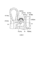
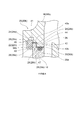
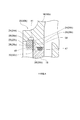
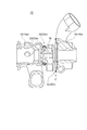
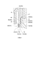
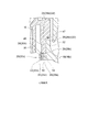
- turbocharger It is a front view sectional view of the turbocharger concerning one embodiment. It is a front view sectional view showing a part of turbocharger concerning one embodiment. It is an expanded sectional view of a part (equivalent to A section in Drawing 2) of a turbocharger concerning one embodiment. It is an expanded sectional view of a part (equivalent to the B section in FIG. 2) of the turbocharger which concerns on one Embodiment. It is an expanded sectional view of a part (equivalent to the B section in FIG. 2) of the turbocharger which concerns on one Embodiment. It is a front view sectional view showing a part of turbocharger concerning one embodiment.
- FIG. 6 It is an expanded sectional view of a part (equivalent to C section in Drawing 6) of a turbocharger concerning one embodiment.
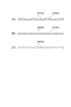
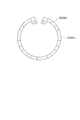
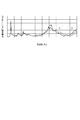
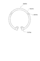
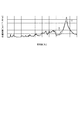
- (A), (B) and (C) are cross-sectional views of a recess according to some embodiments. It is a front view sectional view showing a part of turbocharger concerning one embodiment. It is an expanded sectional view of a part (equivalent to A section in Drawing 2) of a turbocharger concerning one embodiment. It is an expanded sectional view of a part (equivalent to the B section in FIG. 2) of the turbocharger which concerns on one Embodiment. It is a front view of a snap ring (fastening member) concerning one embodiment. It is a graph which shows the noise generation state which concerns on one Embodiment. It is front view sectional drawing of the snap ring (fastening member) which concerns on one Embodiment. It is a graph which shows the noise generation state which concerns on one Embodiment.
- expressions that indicate that things such as “identical”, “equal” and “homogeneous” are equal states not only represent strictly equal states, but also have tolerances or differences with which the same function can be obtained. It also represents the existing state.
- expressions representing shapes such as quadrilateral shapes and cylindrical shapes not only represent shapes such as rectangular shapes and cylindrical shapes in a geometrically strict sense, but also uneven portions and chamfers within the range where the same effect can be obtained. The shape including a part etc. shall also be expressed.
- the expressions “comprising”, “having”, “having”, “including” or “having” one component are not exclusive expressions excluding the presence of other components.
- the rotary machine 10 as shown in FIG. 1, includes a rotating shaft 12, an impeller 14 (14a, 14b) attached to the rotating shaft 12, and an impeller housing 16 (16a, 16b) for accommodating the impeller 14 (14a, 14b). And a bearing housing 18.
- the bearing housing 18 accommodates a bearing 19 rotatably supporting the rotating shaft 12 and is fastened to the impeller housing 16.
- the impeller housing 16 and the bearing housing 18 are fastened in the axial direction of the rotating shaft 12 by fastening members 20 (20a, 20b, 20c). That is, the fastening members 20 (20 a, 20 b, 20 c) apply a fastening force along the axial direction of the rotating shaft 12 to the impeller housing 16 and the bearing housing 18.
- the rotary machine 10 is a turbocharger mounted on an automobile or the like, and the compressor impeller 14 (14a) and the turbine impeller 14 (14b) are attached to both end regions of the rotary shaft 12.
- the compressor impeller 14 (14a) is accommodated in the compressor housing 16 (16a)
- the turbine impeller 14 (14b) is accommodated in the turbine housing 16 (16b).
- a bearing housing 18 is provided between these housings, and the compressor housing 16 (16a) and the bearing housing 18 are axially fastened with a coupling 22 (22a), and the turbine housing 16 (16b) and the bearing housing 18 are , Snap ring 22 (22b).
- exhaust e discharged from an engine rotates the turbine impeller 14 (14b) through the turbine housing 16 (16b).
- the charge air a is drawn into the compressor housing 16 (16a) by the compressor impeller 14 (14a) having the rotation shaft 12, compressed by the compressor housing 16 (16a), and sent to the engine.
- the vibration of the rotary shaft 12 propagates to the respective housings as shown by the arrows, and the respective housings may vibrate to generate radiation noise.
- fasteners 20 (20a, 20b, 20c, 20d) where a fastening force is applied in the direction of the rotational axis by the fastening members 22 (22a, 22b, 22c)
- the impeller housing 16 has an impeller housing side contact surface 24 (24a, 24b) extending in a direction intersecting the axial direction of the rotation shaft 12.
- the impeller housing side contact surface 24 includes an impeller housing side first contact surface 24 (24a) that contacts the fastening member 22, and an impeller housing side second contact surface 24 (24b) that contacts the bearing housing 18.
- the bearing housing 18 has bearing housing side contact surfaces 26 (26a, 26b) extending in a direction intersecting the axial direction of the rotary shaft 12 in the fastening portion 20.
- the bearing housing side contact surface 26 includes a bearing housing side first contact surface 26 (26a) that contacts the fastening member 22, and a bearing housing side second contact surface 26 (26b) that contacts the impeller housing 16.
- the fastening member 22 has a fastening member side contact surface 28 (28a, 28b) extending in a direction intersecting with the axial direction of the rotation shaft 12.
- the fastening member-side abutment surface 28 includes a fastening member-side first abutment surface 28 (28a) in contact with the impeller housing 16 and a fastening member-side second abutment surface 28 (28b) in contact with the bearing housing 18.
- a thin plate member 30 (30a) is provided at least at one position between the contact surface 28 (28b) and the impeller housing side second contact surface 24 (24b) and the bearing housing side second contact surface 26 (26b). , 30b, 30c, 30d) intervene.
- the thin plate member 30 is configured separately from the impeller housing 16, the bearing housing 18, and the fastening member 22.
- the thin plate member 30 is not particularly limited.
- a metal plate or a heat-resistant resin plate-like member having a plate thickness of 0.1 mm to 2.0 mm, preferably 0.5 mm to 1.0 mm can be used.
- the thin plate member 30 intervenes between the two abutting surfaces formed by the impeller housing 16, the bearing housing 18, and the fastening member 22, thereby increasing the contact portion between the two abutting surfaces.
- a slight relative vibration (a minute vibration in a direction along the contact surface) occurs between the two contact surfaces.
- friction is generated between the two contact surfaces, and the shaft vibration from the rotary shaft 12 is attenuated by the friction damping action, so that the vibration and noise generated in the rotary machine 10 can be suppressed.
- the vibration of the rotary shaft 12 causing the vibration of the rotary machine 10 is caused by the weight imbalance of the rotary shaft 12 or the like. Therefore, by suppressing the vibration of the rotary machine 10 with the above configuration, the unbalance allowable value of the rotary shaft 12 can be relaxed, and the manufacturing yield of the rotary shaft 12 can be improved.
- the fastening force between the impeller housing 16, the bearing housing 18, and the fastening member 22 is not as strong in the rotational axis radial direction as in the rotational axis direction. Therefore, a positional deviation in the radial direction of the rotating shaft relatively easily occurs between the two contact surfaces in which the thin plate member 30 intervenes, and the frictional force generated by the positional deviation enhances the vibration damping effect of the turbocharger.
- the impeller housing 16 has an impeller housing side flange portion 34 extending radially outward of the rotating shaft 12, and the bearing housing 18 includes the impeller housing side flange portion 34 and A bearing housing side flange portion 36 that contacts and extends radially outward of the rotating shaft 12 is provided.
- the impeller housing side second abutment surface 24 (24 b) is formed on the impeller housing side flange portion 34, and the bearing housing side second abutment surface 26 (26 b) is formed on the bearing housing side flange portion 36.
- the fastening member 22 (22 a) is a coupling that holds the impeller housing side flange portion 34 and the bearing housing side flange portion 36.
- the impeller housing side first abutment surface 24 (24a), the impeller housing side second abutment surface 24 (24b), the bearing housing side first abutment surface 26 (26a), the bearing housing side second abutment surface 26. (26b), the fastening member side first contact surface 28 (28a), and the fastening member side second contact surface 28 (28b) extend in the direction intersecting the rotation axis direction.
- the fastening member 22 (22a) is a coupling that holds the impeller housing side flange portion 34 and the bearing housing side flange portion 36, it is possible to suppress vibration and noise generated in the rotary machine 10. . Moreover, since the said 2 contact surface which exists in the existing fastening part 20 (20a) is utilized, the remodeling of the rotary machine 10 is not required.
- the impeller housing side flange portion 34 is a flange portion formed on the turbine housing 16 (16b), and the fastening member 22 (22a) is an annular coupling member (V coupling), and has a cross section At both sides, the side portions are curved, and the impeller housing side flange portion 34 and the bearing housing side flange portion 36 are held by this curved portion.
- the impeller housing side second abutment surface 24 (24b) and the bearing housing side second abutment surface 26 (26b) extend along the rotational axis radial direction, as described above, the positional deviation in the rotational axis radial direction Can enhance the vibration damping effect of the rotary machine 10.
- the thin plate member 30 (30 a) is formed of a single thin plate member, and the impeller housing side first contact surface 24 (24 a) and the fastening member side first contact surface 28. (28a) and between the bearing housing side first contact surface 26 (26a) and the fastening member side second contact surface 28 (28b).
- the vibration damping effect can be improved by interposing the thin plate member 30 (30a) between the two contact surfaces to which the pressing force is applied by the coupling 22 (22a), in addition to the above-described operation and effect. Since the thin plate member 30 (30a) is formed of a single thin plate member, manufacture is easy, and it is easy to interpose between the two contact surfaces.
- the thin plate member 30 (30a) has an annular shape and surrounds the impeller housing side flange portion 34 and the bearing housing side flange portion 36 in accordance with the inner side surface of the fastening member 22 (22a) on the cross section. As such, both sides have a curved shape. Thereby, it can be easily arranged in a narrow space between the fastening member 22 (22a) and the impeller housing side flange portion 34 and the bearing housing side flange portion 36.
- the impeller housing 16 has an impeller housing side convex portion 38 extending radially inward of the rotation shaft 12, and the bearing housing 18 is provided radially outside the rotation shaft 12. And a bearing housing side convex portion 40 that abuts against the impeller housing side convex portion 38.
- the impeller housing side second abutment surface 24 (24b) is formed on the impeller housing side convex portion 38, and the bearing housing side second abutment surface 26 (26b) is formed on the bearing housing side convex portion 40. .
- the fastening member 22 (22b) is formed of a snap ring, and the outer peripheral portion of the snap ring is fitted into an annular groove 41 formed in the inner peripheral surface of the impeller housing 16.
- the bearing housing side second abutment surface 26 (26b) is biased to the impeller housing side second abutment surface 24 (24b) by the snap ring 22 (22b).
- the snap ring is configured such that the fastening member 22 (22b) biases the bearing housing side second abutment surface 26 (26b) to the impeller housing side second abutment surface 24 (24b).
- the fastening member 22 (22b) biases the bearing housing side second abutment surface 26 (26b) to the impeller housing side second abutment surface 24 (24b).
- the said 2 contact surface which exists in the existing fastening part 20 (20b) is utilized, remodeling of the rotary machine 10 is not required.
- the thin plate member 30 (30b) is interposed between the impeller housing side second abutment surface 24 (24b) and the bearing housing side second abutment surface 26 (26b). Be done.
- the thin plate member 30 (30b) is interposed between the two contact surfaces to which the pressing force is applied by the snap ring 22 (22b) in addition to the above-described operation and effect. Vibration damping effect can be improved.
- the vibration damping effect of the rotary machine 10 can be enhanced by the positional deviation in the radial direction of the rotation axis. .
- the impeller housing 16 is a turbine housing 16 (16b), and the impeller housing convex part 38 is formed on the turbine housing 16 (16b).
- top surface 38a of the impeller housing side convex portion 38 and the end surface 38b of the turbine housing 16 (16b) other than the top surface 38a form an annular step surface which extends in the rotational axis direction and has a different distance from the rotational shaft 12.
- top surface 40a of the bearing housing side convex portion 40 and the end surface 40b of the bearing housing 18 other than the top surface 40a form an annular step surface along the axial direction of the rotation shaft 12 and having different distances from the rotation shaft 12 .
- the thin plate member 30 (30b) is interposed between the top surface 38a and the end surface 40b, and the first annular portion 42 extending in the axial direction of the rotating shaft 12; 24b) and the bearing housing side second contact surface 26 (26b), the disk portion 44 extending in the radial direction of the rotary shaft 12, and the top surface 40a and the end surface 38b
- the two annular portions 46 are integrally formed.
- a sealing material 47 is interposed between the first annular portion 42 and the bearing housing 18.
- the area of the contact surface between the thin plate member 30 (30b), the impeller housing side second contact surface 24 (24b) and the bearing housing side second contact surface 26 (26b) increases. Since the friction force between the contact surfaces is increased, the vibration damping effect of the rotary machine 10 can be improved.
- the thin plate member 30 (30c) is interposed between the fastening member side second contact surface 28 (28b) and the bearing housing side first contact surface 26 (26a). Be done.
- the vibration damping effect of the rotary machine 10 can be improved by interposing the thin plate member 30 (30c) between the two contact surfaces to which the pressing force is applied by the snap ring 22 (22b). Further, since the thin plate member 30 (30c) is disposed between the two contact surfaces existing in the existing fastening portion 20 (20c), the rotary machine 10 does not need to be modified.
- the fastening member side second contact surface 28 (28b) and the bearing housing side second contact surface 26 (26b) extend along the rotational axis radial direction
- the thin plate member 30 (30c) has a disk shape that is disposed along the radial direction of the rotation shaft 12 and extends in the circumferential direction of the rotation shaft 12. Therefore, relative positional deviation between the fastening member side second contact surface 28 (28b) and the bearing housing side first contact surface 26 (26a) in the rotational axis radial direction is easy during operation of the rotary machine 10 Thus, the frictional force between the two contact surfaces is increased, and the vibration damping effect of the rotary machine 10 can be improved. Further, since the thin plate member 30 (30c) has a simple shape, it can be manufactured at low cost.
- the bearing housing 18 has a bearing housing side extension 48 extending radially outward of the rotating shaft 12.
- the impeller housing 16 is an impeller housing side bolt receiving portion 50 located radially outward of the rotary shaft 12 with respect to the bearing housing side extending portion 48, and an impeller housing side extending portion abutting the bearing housing side extending portion 48.
- an impeller housing side extending portion 52 extending radially inward of the rotary shaft 12 from the impeller housing side bolt receiving portion 50.
- the impeller housing side second abutment surface 24 (24b) is formed on the impeller housing side extension 52, and the bearing housing side second abutment surface 26 (26b) is formed on the bearing housing side extension 48 .
- the impeller housing side second contact surface 24 (24b) and the bearing housing side second contact surface 26 (26b) extend in a direction intersecting the rotation axis direction.
- the fastening member 22 (22c) is a bolt screwed into a screw hole 54 formed in the impeller housing side bolt receiving portion 50.
- the bolt 22 (22c) is screwed into the screw hole 54 to bias the bearing housing side second abutment surface 26 (26b) to the impeller housing side second abutment surface 24 (24b). Ru.
- the fastening member 22 (22c) is a bolt configured to bias the bearing housing side second abutment surface 26 (26b) to the impeller housing side second abutment surface 24 (24b). Vibration and noise generated in the rotary machine 10 can be suppressed in a certain rotary machine 10. In addition, since the above-mentioned two contact surfaces on which the existing fastening portion 20 (20d) is present are used, no modification of the rotary machine 10 is required.
- the thin plate member 30 (30d) is interposed between the impeller housing side second abutment surface 24 (24b) and the bearing housing side second abutment surface 26 (26b). Do.
- the vibration damping effect of the rotary machine 10 can be improved by interposing the thin plate member 30 (30d) between the two contact surfaces to which the pressing force is applied by the bolt 22 (22c).
- the impeller housing side second contact surface 24 (24b) and the bearing housing side second contact surface 26 (26b) extend along the rotational axis radial direction, the operation of the rotary machine 10 is performed.
- the positional displacement between these contact surfaces is easy, the positional displacement increases the frictional force, and the vibration damping effect of the rotary machine 10 can be improved.
- a washer 56 is interposed between the head of the bolt 22 (22c) and the impeller housing side bolt receiving portion 50, and the washer 56 urges the bearing housing side extending portion 48 to the impeller housing side extending portion 52.
- a biasing force This makes it possible to increase the biasing force on the bearing housing side second abutment surface 26 (26b), and between the impeller housing side first abutment surface 24 (24a) and the bearing housing side second abutment surface 26 (26b) Can increase the frictional force generated in the It should be noted that the biasing force may be applied to the bearing housing side extending portion 48 only by the head of the bolt 22 (22c) without using the washer 56.
- One contact surface has at least one recess 32 (32a, 32b, 32c) as shown in FIG.
- the contact area between the thin plate member 30 and the contact surface is reduced by at least one of the two contact surfaces having the recess 32, and the thin plate member 30 and the contact when the vibration occurs It becomes easy to generate micro rattle (micro vibration of the direction which intersects the above-mentioned contact surface) between planes. If a slight rattling occurs between the contact surfaces, the collisional damping action attenuates the axial vibration from the rotating shaft 12. Thereby, the vibration and noise which generate
- the recesses 32 formed in at least one of each of the two abutment surfaces are a plurality of recesses spaced circumferentially about the axis of rotation 12. Including 32. According to the above configuration, the damping effect of the vibration can be further improved by the collision damping action by the plurality of concave portions 32 formed in the circumferential direction of the rotating shaft 12.
- a plurality of recesses having flat surfaces are formed at equal intervals in the circumferential direction of the rotation shaft 12.
- a convex portion 33 (33a) having a flat surface is formed between the concave portions 32 (32a).
- the concave portions 32 (32b) are formed at equal intervals between the convex portions 33 (33b) formed in the waveform cross section.
- the recesses 32 (32c) are formed at equal intervals between the arcs in a cross section in which a plurality of arcs are formed at equal intervals.
- bearings are provided between the impeller housing side first abutment surface 24 (24 a) and the fastening member side first abutment surface 28 (28 a), Between the housing-side first abutment surface 26 (26a) and the fastening member-side second abutment surface 28 (28b), the impeller housing-side second abutment surface 24 (24b) and the bearing housing-side second abutment surface 26
- the thin plate member 30 intervenes in at least one place between (26b).
- the recessed part 32 as shown in FIG. 8 is formed in the at least one surface of said two contact surfaces which the thin-plate member 30 interposes.
- the concave portion 32 is formed in at least one of the two contact surfaces on which the thin plate member 30 is interposed, and thus the friction damping action force due to the friction generated between the thin plate member 30 and the contact surface
- the synergetic effect of the presence of the recess 32 with the friction damping action and the collision damping action can further improve the damping effect of the vibration.
- the bearing housing 18 accommodates a bearing 19 rotatably supporting the rotating shaft 12 and is fastened to the impeller housing 16.
- the impeller housing 16 and the bearing housing 18 are fastened in the axial direction of the rotating shaft 12 by fastening members 20 (20a, 20b, 20c).
- the impeller housing 16 extends in a direction intersecting the axial direction of the rotational axis 12 It has an impeller housing side contact surface 24 (24a, 24b).
- the impeller housing side contact surface 24 includes an impeller housing side first contact surface 24 (24a) that contacts the fastening member 22, and an impeller housing side second contact surface 24 (24b) that contacts the bearing housing 18.
- the bearing housing 18 has bearing housing side contact surfaces 26 (26a, 26b) extending in a direction intersecting the axial direction of the rotary shaft 12 in the fastening portion 20.
- the bearing housing side contact surface 26 includes a bearing housing side first contact surface 26 (26a) that contacts the fastening member 22, and a bearing housing side second contact surface 26 (26b) that contacts the impeller housing 16.
- the fastening member 22 has a fastening member side contact surface 28 (28a, 28b) extending in a direction intersecting with the axial direction of the rotation shaft 12.
- the fastening member-side abutment surface 28 includes a fastening member-side first abutment surface 28 (28a) in contact with the impeller housing 16 and a fastening member-side second abutment surface 28 (28b) in contact with the bearing housing 18.
- the impeller housing side first abutment surface 24 (24a), the impeller housing side second abutment surface 24 (24b), the bearing housing side first abutment surface 26 (26a), At least one contact surface of the bearing housing side second contact surface 26 (26b), the fastening member side first contact surface 28 (28a), and the fastening member side second contact surface 28 (28b) is at least one. It has the recessed part 32 (32a, 32b, 32c).
- At least one recess 32 is provided on at least one of the two contact surfaces formed by the impeller housing 16, the bearing housing 18, and the fastening member 22. Between the contact surfaces, minute relative vibration (minute vibration in the direction along the contact surface) and minute rattle (minute vibration in the direction intersecting the contact surface) are easily generated. When a minute relative vibration occurs between the contact surfaces, friction occurs between the two contact surfaces, and the axial vibration from the rotary shaft 12 is attenuated by the friction damping action. If a slight rattling occurs between the contact surfaces, the collisional damping action attenuates the axial vibration from the rotating shaft 12. Thereby, the vibration and noise which generate
- the vibration of the rotary shaft 12 causing the vibration of the rotary machine 10 is caused by the weight imbalance of the rotary shaft 12 or the like.
- the fastening member 22 (22 a) is a coupling that holds the impeller housing side flange portion 34 and the bearing housing side flange portion 36.
- the impeller housing side first abutment surface 24 (24a), the impeller housing side second abutment surface 24 (24b), the bearing housing side first abutment surface 26 (26a), the bearing housing side second abutment At least one contact surface of the contact surface 26 (26b), the fastening member side first contact surface 28 (28a), and the fastening member side second contact surface 28 (28b) has at least one recess 32.
- the fastening member 22 (22a) is a coupling that holds the impeller housing side flange portion 34 and the bearing housing side flange portion 36, it is possible to suppress vibration and noise generated in the rotary machine 10. .
- the vibration damping effect can be improved by forming the recess 32 in at least one of the two contact surfaces to which the pressing force is applied by the coupling 20 (20a).
- the recessed part 32 is formed in said two contact surfaces which exist in the existing fastening part 20 (20a), the remodeling of the rotary machine 10 is not required.
- the fastening member 22 (22b) is a snap ring for fastening the impeller housing 16 and the bearing housing 18 in the axial direction of the rotation shaft 12.
- the impeller housing side first abutment surface 24 (24a), the impeller housing side second abutment surface 24 (24b), the bearing housing side first abutment surface 26 (26a), the bearing housing side second abutment At least one contact surface of the contact surface 26 (26b), the fastening member side first contact surface 28 (28a), and the fastening member side second contact surface 28 (28b) has at least one recess 32.
- the snap ring is configured such that the fastening member 22 (22b) biases the bearing housing side second abutment surface 26 (26b) to the impeller housing side second abutment surface 24 (24b).
- the fastening member 22 (22b) biases the bearing housing side second abutment surface 26 (26b) to the impeller housing side second abutment surface 24 (24b).
- the vibration damping effect can be improved. Moreover, since the recessed part 32 is formed in said two contact surfaces which exist in the existing fastening part 20 (20b), the remodeling of the rotary machine 10 is not required.
- the impeller housing 16 is a turbine housing 16 (16b), and the impeller housing side first abutment surface 24 (24a), the impeller housing side second abutment surface 24 (24b), and the bearing housing side first A recess 32 is formed in the contact surface 26 (26a).
- FIG. 10B shows an example in which a plurality of recessed portions 32 (32a) are formed at intervals in the circumferential direction of the rotary shaft 12 on the bearing housing side first contact surface 26 (26a).
- the vibration damping effect of the rotary machine 10 can be improved by forming the concave portions 32 (32a) in the three contact surfaces in the fastening portion 20 (20c).
- the bearing housing 18 has a bearing housing side extension 48 extending radially outward of the rotation axis.
- the impeller housing 16 abuts against the impeller housing side bolt receiving portion 50 and the bearing housing side extending portion 48 located radially outward of the bearing housing side extending portion 48 from the impeller housing side bolt receiving portion 50. It has an impeller housing side extending portion 52 extending radially inward in the rotational axis direction.
- the impeller housing side second abutment surface 24 (24 b) is formed with the impeller housing side extension portion 52, and the bearing housing side second abutment surface 26 (26 b) is formed with the bearing housing side extension portion 48.
- the fastening member 22 (22c) is a bolt which is screwed into the screw hole 54 formed in the impeller housing side bolt receiving portion 50, and the bolt is screwed into the screw hole 54 so that the bearing housing side second
- the abutment surface 26 (26b) is biased to the impeller housing side second abutment surface 24 (24b).
- a recess 32 is formed in at least one of the impeller housing side second contact surface 24 (24b) and the bearing housing side second contact surface 26 (26b).
- the fastening member 22 (22c) is a bolt configured to bias the bearing housing side second abutment surface 26 (26b) to the impeller housing side second abutment surface 24 (24b). Vibration and noise generated in the rotary machine 10 can be suppressed in a certain rotary machine 10.
- the vibration damping effect can be improved by forming the recessed part 32 in two contact surfaces to which pushing pressure force is given by bolt 22 (22c). Moreover, since the recessed part 32 is formed using the existing contact surface which exists in the existing fastening member 22 (22c), the remodeling of a rotary machine is not required.
- a plurality of recesses 32 spaced apart in the circumferential direction of the rotating shaft 12 are formed.
- the damping effect of the vibration can be further improved by the collision damping action by the plurality of concave portions 32 formed in the circumferential direction of the rotating shaft 12.
- FIG. 12 shows an example in which the fastening member 22 (22b) is a snap ring and the recess 32 (32a) is formed in the fastening member side second contact surface 28 (28b).
- the snap ring 22 (22b) is mounted on a car turbocharger as shown in FIG. 10, and the result of measuring the state of radiated noise is shown in FIG.
- the line X shows the case where the snap ring 22 (22b) is used
- the line Y shows the case where the surface of the snap ring 22 (22b) is hit off as a comparative example. .
- convex portions 33 (33 a) are formed at four positions on the fastening member side second contact surface 28 (28 b) of the snap ring 22 (22 b), and flat portions are provided except the convex portions 33 (33 a).
- the snap ring 22 (22b) made into the recessed part 32 (32a) is shown.
- the snap ring 22 (22b) is mounted on a car turbocharger as shown in FIG. 10, and the result of measurement of the state of radiated noise is shown in FIG. In FIG.
- the line X shows the case where the snap ring 22 (22b) is used, and the line Y is a snap ring 22 (the second example in which the fastening member side second contact surface 28 (28b) is flat) as a comparative example. 22b) is used.
- vibrations and noise generated in the rotary machine can be suppressed with a simple configuration.
Landscapes
- Engineering & Computer Science (AREA)
- General Engineering & Computer Science (AREA)
- Mechanical Engineering (AREA)
- Chemical & Material Sciences (AREA)
- Combustion & Propulsion (AREA)
- Physics & Mathematics (AREA)
- Acoustics & Sound (AREA)
- Aviation & Aerospace Engineering (AREA)
- Chemical Kinetics & Catalysis (AREA)
- General Chemical & Material Sciences (AREA)
- Supercharger (AREA)
- Structures Of Non-Positive Displacement Pumps (AREA)
Abstract
Priority Applications (5)
| Application Number | Priority Date | Filing Date | Title |
|---|---|---|---|
| CN201680084109.5A CN109219693B (zh) | 2016-03-30 | 2016-03-30 | 旋转机械 |
| PCT/JP2016/060386 WO2017168634A1 (fr) | 2016-03-30 | 2016-03-30 | Machine rotative |
| US16/087,450 US10934887B2 (en) | 2016-03-30 | 2016-03-30 | Rotary machine |
| EP16896853.5A EP3418530B1 (fr) | 2016-03-30 | 2016-03-30 | Machine rotative |
| JP2018507938A JP6606599B2 (ja) | 2016-03-30 | 2016-03-30 | 回転機械 |
Applications Claiming Priority (1)
| Application Number | Priority Date | Filing Date | Title |
|---|---|---|---|
| PCT/JP2016/060386 WO2017168634A1 (fr) | 2016-03-30 | 2016-03-30 | Machine rotative |
Publications (1)
| Publication Number | Publication Date |
|---|---|
| WO2017168634A1 true WO2017168634A1 (fr) | 2017-10-05 |
Family
ID=59963719
Family Applications (1)
| Application Number | Title | Priority Date | Filing Date |
|---|---|---|---|
| PCT/JP2016/060386 Ceased WO2017168634A1 (fr) | 2016-03-30 | 2016-03-30 | Machine rotative |
Country Status (5)
| Country | Link |
|---|---|
| US (1) | US10934887B2 (fr) |
| EP (1) | EP3418530B1 (fr) |
| JP (1) | JP6606599B2 (fr) |
| CN (1) | CN109219693B (fr) |
| WO (1) | WO2017168634A1 (fr) |
Cited By (2)
| Publication number | Priority date | Publication date | Assignee | Title |
|---|---|---|---|---|
| WO2020020640A1 (fr) * | 2018-07-24 | 2020-01-30 | Vitesco Technologies GmbH | Turbocompresseur à gaz d'échappement à comportement acoustique optimisé |
| WO2024150387A1 (fr) * | 2023-01-13 | 2024-07-18 | 三菱重工エンジン&ターボチャージャ株式会社 | Carter de turbocompresseur et turbocompresseur |
Citations (8)
| Publication number | Priority date | Publication date | Assignee | Title |
|---|---|---|---|---|
| JPS63158546U (fr) * | 1987-04-04 | 1988-10-18 | ||
| JPH07189723A (ja) * | 1993-12-27 | 1995-07-28 | Ishikawajima Harima Heavy Ind Co Ltd | ターボチャージャー |
| JP2006090402A (ja) * | 2004-09-22 | 2006-04-06 | Nsk Ltd | ターボチャージャ用回転支持装置 |
| JP2008215083A (ja) * | 2007-02-28 | 2008-09-18 | Mitsubishi Heavy Ind Ltd | 可変容量型排気ターボ過給機における可変ノズル機構部取付構造 |
| US20130154194A1 (en) * | 2010-09-03 | 2013-06-20 | Borgwarner Inc. | Turbocharger housing seal |
| JP2013130136A (ja) * | 2011-12-22 | 2013-07-04 | Mitsubishi Heavy Ind Ltd | ターボチャージャーの締結部構造 |
| JP2013227889A (ja) * | 2012-04-25 | 2013-11-07 | Mitsubishi Electric Corp | 電動過給機 |
| JP2015194092A (ja) * | 2014-03-31 | 2015-11-05 | 株式会社Ihi | 可変ノズルユニット及び可変容量型過給機 |
Family Cites Families (6)
| Publication number | Priority date | Publication date | Assignee | Title |
|---|---|---|---|---|
| US5210945A (en) * | 1991-05-22 | 1993-05-18 | Ngk Spark Plug Co., Ltd. | Method of assembly of a rotary shaft in a ball-bearing type turbocharger |
| CN201306339Y (zh) * | 2008-11-17 | 2009-09-09 | 江阴市万事兴汽车部件制造有限公司 | 新型涡轮增压器用抱箍 |
| JP2010174811A (ja) | 2009-01-30 | 2010-08-12 | Toyota Motor Corp | ターボチャージャの軸受構造 |
| WO2011152454A1 (fr) * | 2010-06-01 | 2011-12-08 | 株式会社Ihi | Turbocompresseur à aube fixe |
| RU2014139847A (ru) * | 2012-03-27 | 2016-05-20 | Боргварнер Инк. | Системы и способы защиты алюминиевого корпуса подшипника турбонагнетателя |
| CN204941691U (zh) * | 2015-07-30 | 2016-01-06 | 浙江巨峰汽车零部件有限公司 | 一种易拆装涡轮增压器 |
-
2016
- 2016-03-30 EP EP16896853.5A patent/EP3418530B1/fr active Active
- 2016-03-30 US US16/087,450 patent/US10934887B2/en active Active
- 2016-03-30 WO PCT/JP2016/060386 patent/WO2017168634A1/fr not_active Ceased
- 2016-03-30 JP JP2018507938A patent/JP6606599B2/ja active Active
- 2016-03-30 CN CN201680084109.5A patent/CN109219693B/zh active Active
Patent Citations (8)
| Publication number | Priority date | Publication date | Assignee | Title |
|---|---|---|---|---|
| JPS63158546U (fr) * | 1987-04-04 | 1988-10-18 | ||
| JPH07189723A (ja) * | 1993-12-27 | 1995-07-28 | Ishikawajima Harima Heavy Ind Co Ltd | ターボチャージャー |
| JP2006090402A (ja) * | 2004-09-22 | 2006-04-06 | Nsk Ltd | ターボチャージャ用回転支持装置 |
| JP2008215083A (ja) * | 2007-02-28 | 2008-09-18 | Mitsubishi Heavy Ind Ltd | 可変容量型排気ターボ過給機における可変ノズル機構部取付構造 |
| US20130154194A1 (en) * | 2010-09-03 | 2013-06-20 | Borgwarner Inc. | Turbocharger housing seal |
| JP2013130136A (ja) * | 2011-12-22 | 2013-07-04 | Mitsubishi Heavy Ind Ltd | ターボチャージャーの締結部構造 |
| JP2013227889A (ja) * | 2012-04-25 | 2013-11-07 | Mitsubishi Electric Corp | 電動過給機 |
| JP2015194092A (ja) * | 2014-03-31 | 2015-11-05 | 株式会社Ihi | 可変ノズルユニット及び可変容量型過給機 |
Cited By (3)
| Publication number | Priority date | Publication date | Assignee | Title |
|---|---|---|---|---|
| WO2020020640A1 (fr) * | 2018-07-24 | 2020-01-30 | Vitesco Technologies GmbH | Turbocompresseur à gaz d'échappement à comportement acoustique optimisé |
| WO2024150387A1 (fr) * | 2023-01-13 | 2024-07-18 | 三菱重工エンジン&ターボチャージャ株式会社 | Carter de turbocompresseur et turbocompresseur |
| JPWO2024150387A1 (fr) * | 2023-01-13 | 2024-07-18 |
Also Published As
| Publication number | Publication date |
|---|---|
| US10934887B2 (en) | 2021-03-02 |
| CN109219693B (zh) | 2021-01-15 |
| EP3418530B1 (fr) | 2020-11-11 |
| EP3418530A4 (fr) | 2019-08-21 |
| JPWO2017168634A1 (ja) | 2018-10-04 |
| JP6606599B2 (ja) | 2019-11-13 |
| CN109219693A (zh) | 2019-01-15 |
| US20190101023A1 (en) | 2019-04-04 |
| EP3418530A1 (fr) | 2018-12-26 |
Similar Documents
| Publication | Publication Date | Title |
|---|---|---|
| US11306619B2 (en) | Seal support structure for a circumferential seal of a gas turbine engine | |
| JP2014092170A (ja) | モータ | |
| JP6575542B2 (ja) | タイヤホイール、ブレーキロータ及びハブの組付構造 | |
| JP6606599B2 (ja) | 回転機械 | |
| JP2016056828A (ja) | ターボ機械 | |
| EP3631221B1 (fr) | Unite de palier pour un rotor de turbocompresseur | |
| JP2018068000A (ja) | 軸受保持構造およびモータ | |
| US11466570B2 (en) | Rotor assembly and rotating machine | |
| JP6421697B2 (ja) | 捩り振動低減装置 | |
| CN111386410B (zh) | 离心摆和用于机动车的驱动装置 | |
| WO2020250577A1 (fr) | Dispositif d'étanchéité | |
| CN115038894B (zh) | 挠性飞轮 | |
| JP7124684B2 (ja) | クランクシャフト装置 | |
| JP2017106563A (ja) | プーリの騒音低減装置 | |
| WO2015041029A1 (fr) | Dispositif amortisseur de type pendule et dispositif de verrouillage de convertisseur de couple | |
| JP7833931B2 (ja) | ダンパ装置 | |
| JP7411432B2 (ja) | トーショナルダンパー | |
| JP2007162792A (ja) | フレキシブルフライホィール装置 | |
| FR2934658A1 (fr) | Double volant amortisseur a moyens d'amortissement perfectionnes | |
| WO2018012171A1 (fr) | Dispositif amortisseur | |
| WO2025047049A1 (fr) | Structure de montage | |
| JP3805627B2 (ja) | 超音波モータ及び超音波モータのロータ | |
| JP2014219031A (ja) | 捩り振動減衰装置 | |
| JP2024073179A (ja) | 車両用アクチュエータ | |
| JP2023043043A (ja) | トーショナルダンパー |
Legal Events
| Date | Code | Title | Description |
|---|---|---|---|
| ENP | Entry into the national phase |
Ref document number: 2018507938 Country of ref document: JP Kind code of ref document: A |
|
| WWE | Wipo information: entry into national phase |
Ref document number: 2016896853 Country of ref document: EP |
|
| ENP | Entry into the national phase |
Ref document number: 2016896853 Country of ref document: EP Effective date: 20180921 |
|
| NENP | Non-entry into the national phase |
Ref country code: DE |
|
| 121 | Ep: the epo has been informed by wipo that ep was designated in this application |
Ref document number: 16896853 Country of ref document: EP Kind code of ref document: A1 |