WO2017169077A1 - Moteur - Google Patents
Moteur Download PDFInfo
- Publication number
- WO2017169077A1 WO2017169077A1 PCT/JP2017/003548 JP2017003548W WO2017169077A1 WO 2017169077 A1 WO2017169077 A1 WO 2017169077A1 JP 2017003548 W JP2017003548 W JP 2017003548W WO 2017169077 A1 WO2017169077 A1 WO 2017169077A1
- Authority
- WO
- WIPO (PCT)
- Prior art keywords
- rotor
- axial direction
- resin
- motor
- hole
- Prior art date
- Legal status (The legal status is an assumption and is not a legal conclusion. Google has not performed a legal analysis and makes no representation as to the accuracy of the status listed.)
- Ceased
Links
Images





Classifications
-
- H—ELECTRICITY
- H02—GENERATION; CONVERSION OR DISTRIBUTION OF ELECTRIC POWER
- H02K—DYNAMO-ELECTRIC MACHINES
- H02K1/00—Details of the magnetic circuit
- H02K1/06—Details of the magnetic circuit characterised by the shape, form or construction
- H02K1/22—Rotating parts of the magnetic circuit
- H02K1/28—Means for mounting or fastening rotating magnetic parts on to, or to, the rotor structures
-
- H—ELECTRICITY
- H02—GENERATION; CONVERSION OR DISTRIBUTION OF ELECTRIC POWER
- H02K—DYNAMO-ELECTRIC MACHINES
- H02K1/00—Details of the magnetic circuit
- H02K1/06—Details of the magnetic circuit characterised by the shape, form or construction
- H02K1/22—Rotating parts of the magnetic circuit
- H02K1/28—Means for mounting or fastening rotating magnetic parts on to, or to, the rotor structures
- H02K1/30—Means for mounting or fastening rotating magnetic parts on to, or to, the rotor structures using intermediate parts, e.g. spiders
-
- F—MECHANICAL ENGINEERING; LIGHTING; HEATING; WEAPONS; BLASTING
- F04—POSITIVE - DISPLACEMENT MACHINES FOR LIQUIDS; PUMPS FOR LIQUIDS OR ELASTIC FLUIDS
- F04D—NON-POSITIVE-DISPLACEMENT PUMPS
- F04D19/00—Axial-flow pumps
- F04D19/002—Axial flow fans
-
- F—MECHANICAL ENGINEERING; LIGHTING; HEATING; WEAPONS; BLASTING
- F04—POSITIVE - DISPLACEMENT MACHINES FOR LIQUIDS; PUMPS FOR LIQUIDS OR ELASTIC FLUIDS
- F04D—NON-POSITIVE-DISPLACEMENT PUMPS
- F04D29/00—Details, component parts, or accessories
- F04D29/18—Rotors
- F04D29/181—Axial flow rotors
-
- H—ELECTRICITY
- H02—GENERATION; CONVERSION OR DISTRIBUTION OF ELECTRIC POWER
- H02K—DYNAMO-ELECTRIC MACHINES
- H02K1/00—Details of the magnetic circuit
- H02K1/06—Details of the magnetic circuit characterised by the shape, form or construction
- H02K1/22—Rotating parts of the magnetic circuit
- H02K1/27—Rotor cores with permanent magnets
- H02K1/2706—Inner rotors
- H02K1/272—Inner rotors the magnetisation axis of the magnets being perpendicular to the rotor axis
- H02K1/274—Inner rotors the magnetisation axis of the magnets being perpendicular to the rotor axis the rotor consisting of two or more circumferentially positioned magnets
- H02K1/2753—Inner rotors the magnetisation axis of the magnets being perpendicular to the rotor axis the rotor consisting of two or more circumferentially positioned magnets the rotor consisting of magnets or groups of magnets arranged with alternating polarity
- H02K1/276—Magnets embedded in the magnetic core, e.g. interior permanent magnets [IPM]
-
- H—ELECTRICITY
- H02—GENERATION; CONVERSION OR DISTRIBUTION OF ELECTRIC POWER
- H02K—DYNAMO-ELECTRIC MACHINES
- H02K1/00—Details of the magnetic circuit
- H02K1/06—Details of the magnetic circuit characterised by the shape, form or construction
- H02K1/22—Rotating parts of the magnetic circuit
- H02K1/32—Rotating parts of the magnetic circuit with channels or ducts for flow of cooling medium
-
- H—ELECTRICITY
- H02—GENERATION; CONVERSION OR DISTRIBUTION OF ELECTRIC POWER
- H02K—DYNAMO-ELECTRIC MACHINES
- H02K11/00—Structural association of dynamo-electric machines with electric components or with devices for shielding, monitoring or protection
- H02K11/30—Structural association with control circuits or drive circuits
-
- H—ELECTRICITY
- H02—GENERATION; CONVERSION OR DISTRIBUTION OF ELECTRIC POWER
- H02K—DYNAMO-ELECTRIC MACHINES
- H02K15/00—Processes or apparatus specially adapted for manufacturing, assembling, maintaining or repairing of dynamo-electric machines
- H02K15/12—Impregnating, moulding insulation, heating or drying of windings, stators, rotors or machines
-
- H—ELECTRICITY
- H02—GENERATION; CONVERSION OR DISTRIBUTION OF ELECTRIC POWER
- H02K—DYNAMO-ELECTRIC MACHINES
- H02K21/00—Synchronous motors having permanent magnets; Synchronous generators having permanent magnets
- H02K21/12—Synchronous motors having permanent magnets; Synchronous generators having permanent magnets with stationary armatures and rotating magnets
- H02K21/14—Synchronous motors having permanent magnets; Synchronous generators having permanent magnets with stationary armatures and rotating magnets with magnets rotating within the armatures
- H02K21/16—Synchronous motors having permanent magnets; Synchronous generators having permanent magnets with stationary armatures and rotating magnets with magnets rotating within the armatures having annular armature cores with salient poles
-
- H—ELECTRICITY
- H02—GENERATION; CONVERSION OR DISTRIBUTION OF ELECTRIC POWER
- H02K—DYNAMO-ELECTRIC MACHINES
- H02K5/00—Casings; Enclosures; Supports
- H02K5/04—Casings or enclosures characterised by the shape, form or construction thereof
- H02K5/16—Means for supporting bearings, e.g. insulating supports or means for fitting bearings in the bearing-shields
- H02K5/173—Means for supporting bearings, e.g. insulating supports or means for fitting bearings in the bearing-shields using bearings with rolling contact, e.g. ball bearings
- H02K5/1732—Means for supporting bearings, e.g. insulating supports or means for fitting bearings in the bearing-shields using bearings with rolling contact, e.g. ball bearings radially supporting the rotary shaft at both ends of the rotor
-
- H—ELECTRICITY
- H02—GENERATION; CONVERSION OR DISTRIBUTION OF ELECTRIC POWER
- H02K—DYNAMO-ELECTRIC MACHINES
- H02K5/00—Casings; Enclosures; Supports
- H02K5/04—Casings or enclosures characterised by the shape, form or construction thereof
- H02K5/22—Auxiliary parts of casings not covered by groups H02K5/06-H02K5/20, e.g. shaped to form connection boxes or terminal boxes
- H02K5/225—Terminal boxes or connection arrangements
-
- H—ELECTRICITY
- H02—GENERATION; CONVERSION OR DISTRIBUTION OF ELECTRIC POWER
- H02K—DYNAMO-ELECTRIC MACHINES
- H02K7/00—Arrangements for handling mechanical energy structurally associated with dynamo-electric machines, e.g. structural association with mechanical driving motors or auxiliary dynamo-electric machines
- H02K7/08—Structural association with bearings
- H02K7/083—Structural association with bearings radially supporting the rotary shaft at both ends of the rotor
-
- H—ELECTRICITY
- H02—GENERATION; CONVERSION OR DISTRIBUTION OF ELECTRIC POWER
- H02K—DYNAMO-ELECTRIC MACHINES
- H02K7/00—Arrangements for handling mechanical energy structurally associated with dynamo-electric machines, e.g. structural association with mechanical driving motors or auxiliary dynamo-electric machines
- H02K7/14—Structural association with mechanical loads, e.g. with hand-held machine tools or fans
-
- H—ELECTRICITY
- H02—GENERATION; CONVERSION OR DISTRIBUTION OF ELECTRIC POWER
- H02K—DYNAMO-ELECTRIC MACHINES
- H02K9/00—Arrangements for cooling or ventilating
- H02K9/02—Arrangements for cooling or ventilating by ambient air flowing through the machine
-
- H—ELECTRICITY
- H02—GENERATION; CONVERSION OR DISTRIBUTION OF ELECTRIC POWER
- H02K—DYNAMO-ELECTRIC MACHINES
- H02K9/00—Arrangements for cooling or ventilating
- H02K9/02—Arrangements for cooling or ventilating by ambient air flowing through the machine
- H02K9/04—Arrangements for cooling or ventilating by ambient air flowing through the machine having means for generating a flow of cooling medium
- H02K9/06—Arrangements for cooling or ventilating by ambient air flowing through the machine having means for generating a flow of cooling medium with fans or impellers driven by the machine shaft
-
- H—ELECTRICITY
- H02—GENERATION; CONVERSION OR DISTRIBUTION OF ELECTRIC POWER
- H02K—DYNAMO-ELECTRIC MACHINES
- H02K2211/00—Specific aspects not provided for in the other groups of this subclass relating to measuring or protective devices or electric components
- H02K2211/03—Machines characterised by circuit boards, e.g. pcb
-
- H—ELECTRICITY
- H02—GENERATION; CONVERSION OR DISTRIBUTION OF ELECTRIC POWER
- H02K—DYNAMO-ELECTRIC MACHINES
- H02K2213/00—Specific aspects, not otherwise provided for and not covered by codes H02K2201/00 - H02K2211/00
- H02K2213/03—Machines characterised by numerical values, ranges, mathematical expressions or similar information
Definitions
- FIG. 1 is a schematic plan view showing an electric fan 1 according to the present embodiment.
- FIG. 2 is a schematic side view showing the electric fan 1 according to the present embodiment.
- the electric fan 1 has a motor 2 and an impeller 3.
- the impeller 3 is attached to the motor 2 via a protruding portion 130 described later that the motor 2 has.
- the impeller 3 is directly attached to the protrusion 130.
- the impeller 3 may be indirectly attached to the protrusion 130.
- the impeller 3 is arranged on one side in the axial direction of the motor 2 and rotates around the central axis A.
- the direction in which the impeller 3 is disposed with respect to the motor 2 is referred to as one axial direction, and the opposite direction is referred to as the other axial direction. *
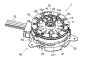
- the stator 20 is located on the radially outer side of the rotor 10.
- the stator 20 includes a stator core 21, an insulator 22, and a coil 23.
- the stator core 21 is formed by laminating a plurality of magnetic steel plates.
- the stator core 21 may be formed by joining a plurality of core pieces.
- the inner peripheral surface of the stator core 21 faces the outer peripheral surface of the rotor 10.
- the stator core 21 has an annular core back 211 and a plurality of teeth 212 protruding radially inward from the core back 211.
- the plurality of teeth 212 are arranged at equal intervals in the circumferential direction.
- the plurality of teeth 212 are covered by the insulator 22.
- the insulator 22 is an insulating member (for example, resin).
- the coil 23 is formed by winding a conductive wire around each tooth 212 via the insulator 22. *
- the holder 40 supports the stator 20.
- the holder 40 has a bracket 50 disposed on the other side in the axial direction.
- the shape of the bracket 50 is substantially circular.
- a shaft 41 extending in the axial direction is fixed to the central portion of the bracket 50.
- the center of the shaft 41 coincides with the central axis A.
- the bearing portion 30 is located between the rotor 10 and the shaft 41, and the rotor 10 is provided to be rotatable with respect to the shaft 41.
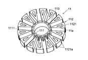
- Each connecting portion 113 extends in the radial direction and connects one outer core element 1121 and the inner core portion 111.
- the connecting portion 113 connects the circumferential center of the radially inner end of the outer core element 1121 and the outer peripheral surface of the inner core portion 111.
- the width of each connecting portion 113 in the circumferential direction is preferably narrow. Thereby, it can suppress that magnetic flux flows into the inner core part 111.
- the inner core portion 111, the outer core portion 112, and the plurality of connecting portions 113 are a single member. *
Landscapes
- Engineering & Computer Science (AREA)
- Power Engineering (AREA)
- Mechanical Engineering (AREA)
- General Engineering & Computer Science (AREA)
- Manufacturing & Machinery (AREA)
- Structures Of Non-Positive Displacement Pumps (AREA)
- Connection Of Motors, Electrical Generators, Mechanical Devices, And The Like (AREA)
- Motor Or Generator Cooling System (AREA)
- Iron Core Of Rotating Electric Machines (AREA)
Abstract
L'invention concerne un moteur de type à rotor interne, et comporte : un rotor qui tourne autour d'un axe central ; et un stator qui est positionné à l'extérieur du rotor dans la direction radiale. Le rotor comporte un noyau de rotor et une partie résineuse qui recouvre au moins une partie du noyau de rotor. De plus, le noyau de rotor comporte une pluralité de trous traversants qui traversent ce dernier dans la direction axiale. La partie résineuse comporte : une première partie résineuse qui recouvre au moins une partie de la surface d'extrémité du noyau de rotor d'un côté dans la direction axiale ; et une partie d'extension qui est prévue au niveau d'au moins un trou traversant de la pluralité de trous traversants, et qui s'étend depuis la première partie résineuse dans le trou traversant dans la direction axiale. La première partie résineuse comporte une partie en saillie qui fait saillie vers l'un des côtés dans la direction axiale. La partie en saillie et la partie d'extension se chevauchent dans une vue en plan depuis la direction axiale.
Priority Applications (4)
| Application Number | Priority Date | Filing Date | Title |
|---|---|---|---|
| DE112017001782.3T DE112017001782T5 (de) | 2016-03-31 | 2017-02-01 | Motor |
| CN201780020720.6A CN109075661A (zh) | 2016-03-31 | 2017-02-01 | 马达 |
| JP2018508473A JPWO2017169077A1 (ja) | 2016-03-31 | 2017-02-01 | モータ |
| US16/148,191 US20190036403A1 (en) | 2016-03-31 | 2018-10-01 | Motor |
Applications Claiming Priority (2)
| Application Number | Priority Date | Filing Date | Title |
|---|---|---|---|
| JP2016070269 | 2016-03-31 | ||
| JP2016-070269 | 2016-03-31 |
Related Child Applications (1)
| Application Number | Title | Priority Date | Filing Date |
|---|---|---|---|
| US16/148,191 Continuation US20190036403A1 (en) | 2016-03-31 | 2018-10-01 | Motor |
Publications (1)
| Publication Number | Publication Date |
|---|---|
| WO2017169077A1 true WO2017169077A1 (fr) | 2017-10-05 |
Family
ID=59962842
Family Applications (1)
| Application Number | Title | Priority Date | Filing Date |
|---|---|---|---|
| PCT/JP2017/003548 Ceased WO2017169077A1 (fr) | 2016-03-31 | 2017-02-01 | Moteur |
Country Status (5)
| Country | Link |
|---|---|
| US (1) | US20190036403A1 (fr) |
| JP (1) | JPWO2017169077A1 (fr) |
| CN (1) | CN109075661A (fr) |
| DE (1) | DE112017001782T5 (fr) |
| WO (1) | WO2017169077A1 (fr) |
Families Citing this family (2)
| Publication number | Priority date | Publication date | Assignee | Title |
|---|---|---|---|---|
| DE102017129212A1 (de) * | 2017-12-08 | 2019-06-13 | Dr. Ing. H.C. F. Porsche Aktiengesellschaft | Rotor mit Kühlung |
| JP7327756B2 (ja) * | 2019-05-29 | 2023-08-16 | ニデックテクノモータ株式会社 | ロータおよびモータ |
Citations (6)
| Publication number | Priority date | Publication date | Assignee | Title |
|---|---|---|---|---|
| JPH0397353U (fr) * | 1990-01-23 | 1991-10-07 | ||
| JPH07312852A (ja) * | 1994-05-13 | 1995-11-28 | Yaskawa Electric Corp | 永久磁石形回転子の製造方法 |
| JP2014036457A (ja) * | 2012-08-07 | 2014-02-24 | Nippon Densan Corp | ロータ、モータ、およびロータの製造方法 |
| US20140191623A1 (en) * | 2011-09-12 | 2014-07-10 | Brose Fahrzeugteile Gmbh & Co. Kommanditgesellschaft, Wuerzburg | Breathing electric motor |
| JP2014150688A (ja) * | 2013-02-01 | 2014-08-21 | Aisin Seiki Co Ltd | ロータおよび回転電機 |
| JP2014230348A (ja) * | 2013-05-21 | 2014-12-08 | 日本電産株式会社 | ロータおよびモータ |
Family Cites Families (1)
| Publication number | Priority date | Publication date | Assignee | Title |
|---|---|---|---|---|
| JP4803253B2 (ja) * | 2006-04-26 | 2011-10-26 | 株式会社村田製作所 | 給電回路基板付き物品 |
-
2017
- 2017-02-01 CN CN201780020720.6A patent/CN109075661A/zh not_active Withdrawn
- 2017-02-01 JP JP2018508473A patent/JPWO2017169077A1/ja not_active Withdrawn
- 2017-02-01 WO PCT/JP2017/003548 patent/WO2017169077A1/fr not_active Ceased
- 2017-02-01 DE DE112017001782.3T patent/DE112017001782T5/de not_active Withdrawn
-
2018
- 2018-10-01 US US16/148,191 patent/US20190036403A1/en not_active Abandoned
Patent Citations (6)
| Publication number | Priority date | Publication date | Assignee | Title |
|---|---|---|---|---|
| JPH0397353U (fr) * | 1990-01-23 | 1991-10-07 | ||
| JPH07312852A (ja) * | 1994-05-13 | 1995-11-28 | Yaskawa Electric Corp | 永久磁石形回転子の製造方法 |
| US20140191623A1 (en) * | 2011-09-12 | 2014-07-10 | Brose Fahrzeugteile Gmbh & Co. Kommanditgesellschaft, Wuerzburg | Breathing electric motor |
| JP2014036457A (ja) * | 2012-08-07 | 2014-02-24 | Nippon Densan Corp | ロータ、モータ、およびロータの製造方法 |
| JP2014150688A (ja) * | 2013-02-01 | 2014-08-21 | Aisin Seiki Co Ltd | ロータおよび回転電機 |
| JP2014230348A (ja) * | 2013-05-21 | 2014-12-08 | 日本電産株式会社 | ロータおよびモータ |
Also Published As
| Publication number | Publication date |
|---|---|
| CN109075661A (zh) | 2018-12-21 |
| DE112017001782T5 (de) | 2018-12-13 |
| US20190036403A1 (en) | 2019-01-31 |
| JPWO2017169077A1 (ja) | 2019-02-07 |
Similar Documents
| Publication | Publication Date | Title |
|---|---|---|
| JP7080621B2 (ja) | アウターロータモータ及びこれを備える掃除機 | |
| JP2020099197A (ja) | モータ | |
| JP6372756B2 (ja) | モータおよびそれを備えた電動工具 | |
| WO2017033917A1 (fr) | Moteur | |
| WO2017170297A1 (fr) | Moteur | |
| JP2020133550A (ja) | 軸流ファン | |
| US10224777B2 (en) | Brushless motor with water stopping walls creating labyrinth structure | |
| WO2018008356A1 (fr) | Machine tournante | |
| WO2017169077A1 (fr) | Moteur | |
| JP2019161832A (ja) | モータおよびファンモータ | |
| JP2025175103A (ja) | モータ | |
| KR20170032023A (ko) | 로터 및 이를 포함하는 모터 | |
| JP6172234B2 (ja) | 電動機および送風装置 | |
| JP5290608B2 (ja) | アキシャルギャップモータ | |
| JP6088275B2 (ja) | ステッピングモータ | |
| WO2021200475A1 (fr) | Moteur à aimants permanents | |
| US20250109750A1 (en) | Motor and fan motor | |
| JP6399070B2 (ja) | 回転電機 | |
| JP7359068B2 (ja) | 電動機 | |
| JP7400597B2 (ja) | 電動機 | |
| US11296562B2 (en) | Stator element, stator assembly, motor, and electromechanical device | |
| JP2010075026A (ja) | モータ | |
| JP2024033446A (ja) | モータ及びファン装置 | |
| JP2019122059A (ja) | ブラシ付モータ、及びラジエータ冷却用ファンモータ | |
| JP2019022325A (ja) | モータ |
Legal Events
| Date | Code | Title | Description |
|---|---|---|---|
| ENP | Entry into the national phase |
Ref document number: 2018508473 Country of ref document: JP Kind code of ref document: A |
|
| 121 | Ep: the epo has been informed by wipo that ep was designated in this application |
Ref document number: 17773626 Country of ref document: EP Kind code of ref document: A1 |
|
| 122 | Ep: pct application non-entry in european phase |
Ref document number: 17773626 Country of ref document: EP Kind code of ref document: A1 |