WO2017169083A1 - 画像撮像装置及び画像撮像方法 - Google Patents
画像撮像装置及び画像撮像方法 Download PDFInfo
- Publication number
- WO2017169083A1 WO2017169083A1 PCT/JP2017/003695 JP2017003695W WO2017169083A1 WO 2017169083 A1 WO2017169083 A1 WO 2017169083A1 JP 2017003695 W JP2017003695 W JP 2017003695W WO 2017169083 A1 WO2017169083 A1 WO 2017169083A1
- Authority
- WO
- WIPO (PCT)
- Prior art keywords
- light
- wavelengths
- transmitted
- fluorescence
- light source
- Prior art date
- Legal status (The legal status is an assumption and is not a legal conclusion. Google has not performed a legal analysis and makes no representation as to the accuracy of the status listed.)
- Ceased
Links
Images





Classifications
-
- G—PHYSICS
- G01—MEASURING; TESTING
- G01N—INVESTIGATING OR ANALYSING MATERIALS BY DETERMINING THEIR CHEMICAL OR PHYSICAL PROPERTIES
- G01N21/00—Investigating or analysing materials by the use of optical means, i.e. using sub-millimetre waves, infrared, visible or ultraviolet light
- G01N21/62—Systems in which the material investigated is excited whereby it emits light or causes a change in wavelength of the incident light
- G01N21/63—Systems in which the material investigated is excited whereby it emits light or causes a change in wavelength of the incident light optically excited
- G01N21/64—Fluorescence; Phosphorescence
- G01N21/645—Specially adapted constructive features of fluorimeters
- G01N21/6456—Spatial resolved fluorescence measurements; Imaging
-
- G—PHYSICS
- G01—MEASURING; TESTING
- G01J—MEASUREMENT OF INTENSITY, VELOCITY, SPECTRAL CONTENT, POLARISATION, PHASE OR PULSE CHARACTERISTICS OF INFRARED, VISIBLE OR ULTRAVIOLET LIGHT; COLORIMETRY; RADIATION PYROMETRY
- G01J3/00—Spectrometry; Spectrophotometry; Monochromators; Measuring colours
- G01J3/28—Investigating the spectrum
- G01J3/2803—Investigating the spectrum using photoelectric array detector
-
- G—PHYSICS
- G01—MEASURING; TESTING
- G01J—MEASUREMENT OF INTENSITY, VELOCITY, SPECTRAL CONTENT, POLARISATION, PHASE OR PULSE CHARACTERISTICS OF INFRARED, VISIBLE OR ULTRAVIOLET LIGHT; COLORIMETRY; RADIATION PYROMETRY
- G01J3/00—Spectrometry; Spectrophotometry; Monochromators; Measuring colours
- G01J3/28—Investigating the spectrum
- G01J3/44—Raman spectrometry; Scattering spectrometry ; Fluorescence spectrometry
- G01J3/4406—Fluorescence spectrometry
-
- G—PHYSICS
- G01—MEASURING; TESTING
- G01J—MEASUREMENT OF INTENSITY, VELOCITY, SPECTRAL CONTENT, POLARISATION, PHASE OR PULSE CHARACTERISTICS OF INFRARED, VISIBLE OR ULTRAVIOLET LIGHT; COLORIMETRY; RADIATION PYROMETRY
- G01J3/00—Spectrometry; Spectrophotometry; Monochromators; Measuring colours
- G01J3/46—Measurement of colour; Colour measuring devices, e.g. colorimeters
- G01J3/50—Measurement of colour; Colour measuring devices, e.g. colorimeters using electric radiation detectors
- G01J3/502—Measurement of colour; Colour measuring devices, e.g. colorimeters using electric radiation detectors using a dispersive element, e.g. grating, prism
-
- G—PHYSICS
- G01—MEASURING; TESTING
- G01N—INVESTIGATING OR ANALYSING MATERIALS BY DETERMINING THEIR CHEMICAL OR PHYSICAL PROPERTIES
- G01N21/00—Investigating or analysing materials by the use of optical means, i.e. using sub-millimetre waves, infrared, visible or ultraviolet light
- G01N21/62—Systems in which the material investigated is excited whereby it emits light or causes a change in wavelength of the incident light
- G01N21/63—Systems in which the material investigated is excited whereby it emits light or causes a change in wavelength of the incident light optically excited
- G01N21/64—Fluorescence; Phosphorescence
-
- G—PHYSICS
- G01—MEASURING; TESTING
- G01N—INVESTIGATING OR ANALYSING MATERIALS BY DETERMINING THEIR CHEMICAL OR PHYSICAL PROPERTIES
- G01N21/00—Investigating or analysing materials by the use of optical means, i.e. using sub-millimetre waves, infrared, visible or ultraviolet light
- G01N21/62—Systems in which the material investigated is excited whereby it emits light or causes a change in wavelength of the incident light
- G01N21/63—Systems in which the material investigated is excited whereby it emits light or causes a change in wavelength of the incident light optically excited
- G01N21/64—Fluorescence; Phosphorescence
- G01N21/6428—Measuring fluorescence of fluorescent products of reactions or of fluorochrome labelled reactive substances, e.g. measuring quenching effects, using measuring "optrodes"
-
- G—PHYSICS
- G01—MEASURING; TESTING
- G01N—INVESTIGATING OR ANALYSING MATERIALS BY DETERMINING THEIR CHEMICAL OR PHYSICAL PROPERTIES
- G01N21/00—Investigating or analysing materials by the use of optical means, i.e. using sub-millimetre waves, infrared, visible or ultraviolet light
- G01N21/62—Systems in which the material investigated is excited whereby it emits light or causes a change in wavelength of the incident light
- G01N21/63—Systems in which the material investigated is excited whereby it emits light or causes a change in wavelength of the incident light optically excited
- G01N21/64—Fluorescence; Phosphorescence
- G01N21/645—Specially adapted constructive features of fluorimeters
- G01N21/6456—Spatial resolved fluorescence measurements; Imaging
- G01N21/6458—Fluorescence microscopy
-
- G—PHYSICS
- G01—MEASURING; TESTING
- G01N—INVESTIGATING OR ANALYSING MATERIALS BY DETERMINING THEIR CHEMICAL OR PHYSICAL PROPERTIES
- G01N33/00—Investigating or analysing materials by specific methods not covered by groups G01N1/00 - G01N31/00
- G01N33/48—Biological material, e.g. blood, urine; Haemocytometers
- G01N33/50—Chemical analysis of biological material, e.g. blood, urine; Testing involving biospecific ligand binding methods; Immunological testing
- G01N33/58—Chemical analysis of biological material, e.g. blood, urine; Testing involving biospecific ligand binding methods; Immunological testing involving labelled substances
- G01N33/582—Chemical analysis of biological material, e.g. blood, urine; Testing involving biospecific ligand binding methods; Immunological testing involving labelled substances with fluorescent label
-
- G—PHYSICS
- G02—OPTICS
- G02B—OPTICAL ELEMENTS, SYSTEMS OR APPARATUS
- G02B21/00—Microscopes
- G02B21/0004—Microscopes specially adapted for specific applications
- G02B21/002—Scanning microscopes
- G02B21/0024—Confocal scanning microscopes (CSOMs) or confocal "macroscopes"; Accessories which are not restricted to use with CSOMs, e.g. sample holders
- G02B21/0052—Optical details of the image generation
- G02B21/0076—Optical details of the image generation arrangements using fluorescence or luminescence
-
- G—PHYSICS
- G01—MEASURING; TESTING
- G01J—MEASUREMENT OF INTENSITY, VELOCITY, SPECTRAL CONTENT, POLARISATION, PHASE OR PULSE CHARACTERISTICS OF INFRARED, VISIBLE OR ULTRAVIOLET LIGHT; COLORIMETRY; RADIATION PYROMETRY
- G01J3/00—Spectrometry; Spectrophotometry; Monochromators; Measuring colours
- G01J3/12—Generating the spectrum; Monochromators
- G01J2003/1213—Filters in general, e.g. dichroic, band
-
- G—PHYSICS
- G01—MEASURING; TESTING
- G01J—MEASUREMENT OF INTENSITY, VELOCITY, SPECTRAL CONTENT, POLARISATION, PHASE OR PULSE CHARACTERISTICS OF INFRARED, VISIBLE OR ULTRAVIOLET LIGHT; COLORIMETRY; RADIATION PYROMETRY
- G01J3/00—Spectrometry; Spectrophotometry; Monochromators; Measuring colours
- G01J3/28—Investigating the spectrum
- G01J3/2823—Imaging spectrometer
- G01J2003/2826—Multispectral imaging, e.g. filter imaging
-
- G—PHYSICS
- G01—MEASURING; TESTING
- G01N—INVESTIGATING OR ANALYSING MATERIALS BY DETERMINING THEIR CHEMICAL OR PHYSICAL PROPERTIES
- G01N21/00—Investigating or analysing materials by the use of optical means, i.e. using sub-millimetre waves, infrared, visible or ultraviolet light
- G01N21/62—Systems in which the material investigated is excited whereby it emits light or causes a change in wavelength of the incident light
- G01N21/63—Systems in which the material investigated is excited whereby it emits light or causes a change in wavelength of the incident light optically excited
- G01N21/64—Fluorescence; Phosphorescence
- G01N2021/6417—Spectrofluorimetric devices
- G01N2021/6421—Measuring at two or more wavelengths
-
- G—PHYSICS
- G01—MEASURING; TESTING
- G01N—INVESTIGATING OR ANALYSING MATERIALS BY DETERMINING THEIR CHEMICAL OR PHYSICAL PROPERTIES
- G01N21/00—Investigating or analysing materials by the use of optical means, i.e. using sub-millimetre waves, infrared, visible or ultraviolet light
- G01N21/62—Systems in which the material investigated is excited whereby it emits light or causes a change in wavelength of the incident light
- G01N21/63—Systems in which the material investigated is excited whereby it emits light or causes a change in wavelength of the incident light optically excited
- G01N21/64—Fluorescence; Phosphorescence
- G01N21/6428—Measuring fluorescence of fluorescent products of reactions or of fluorochrome labelled reactive substances, e.g. measuring quenching effects, using measuring "optrodes"
- G01N2021/6439—Measuring fluorescence of fluorescent products of reactions or of fluorochrome labelled reactive substances, e.g. measuring quenching effects, using measuring "optrodes" with indicators, stains, dyes, tags, labels, marks
- G01N2021/6441—Measuring fluorescence of fluorescent products of reactions or of fluorochrome labelled reactive substances, e.g. measuring quenching effects, using measuring "optrodes" with indicators, stains, dyes, tags, labels, marks with two or more labels
-
- G—PHYSICS
- G01—MEASURING; TESTING
- G01N—INVESTIGATING OR ANALYSING MATERIALS BY DETERMINING THEIR CHEMICAL OR PHYSICAL PROPERTIES
- G01N21/00—Investigating or analysing materials by the use of optical means, i.e. using sub-millimetre waves, infrared, visible or ultraviolet light
- G01N21/62—Systems in which the material investigated is excited whereby it emits light or causes a change in wavelength of the incident light
- G01N21/63—Systems in which the material investigated is excited whereby it emits light or causes a change in wavelength of the incident light optically excited
- G01N21/64—Fluorescence; Phosphorescence
- G01N21/645—Specially adapted constructive features of fluorimeters
- G01N2021/6463—Optics
- G01N2021/6471—Special filters, filter wheel
Definitions
- the present invention relates to an image capturing device and an image capturing method.
- a fluorescence microscope or the like is used as an image pickup device.
- Patent Document 1 light from a laser light source is collected by a microlens, light having an arbitrary wavelength is transmitted as excitation light by a dichroic mirror, the sample is irradiated with excitation light through a pinhole, and fluorescence from the sample is emitted. Is recorded with a CCD (charge-coupled device) camera.
- CCD charge-coupled device
- Patent Document 2 describes that a plurality of types of fluorescence emitted from a sample are transmitted through a wavelength tunable liquid crystal spectral filter in which the wavelength band of transmitted light is variable and imaged by a detector.
- an image pickup apparatus that picks up fluorescence emitted from a sample is required to pick up fluorescence of different wavelengths by one shooting from the viewpoint of shortening time.
- Patent Document 1 does not disclose a specific configuration of an image sensor for imaging fluorescence. Further, in Patent Document 2, the wavelength tunable liquid crystal spectral filter is imaged while changing the wavelength range of the transmitted light, and it is also possible to image fluorescence of different wavelengths by one image capturing. There is also no disclosure of a specific configuration of an image sensor that images fluorescence.
- the present invention has been made in view of such circumstances, and an object thereof is to provide an image imaging apparatus and an image imaging method capable of imaging a plurality of fluorescence from a cell by one imaging. It is another object of the present invention to provide an image capturing apparatus and an image capturing method capable of capturing a plurality of fluorescence from a cell and transmitted light from the cell by one photographing.
- an image capturing apparatus includes at least one storage unit that stores and stores cells stained with a plurality of types of fluorescent dyes that emit fluorescence of different wavelengths, on a flat holding surface, and a plurality of storage units.
- a first light source that simultaneously emits light of a wavelength; and a first multiband that selectively transmits excitation light of a plurality of wavelengths that excites a plurality of types of fluorescent dyes among light of a plurality of wavelengths emitted from the first light source.
- a dichroic mirror that irradiates a cell with a plurality of wavelengths of excitation light that has passed through the first multiband pass filter and transmits fluorescence of different wavelengths emitted from the cell by the plurality of wavelengths of excitation light; and a dichroic A filter group including a second multi-band pass filter that transmits fluorescence of different wavelengths transmitted through the mirror, and a plurality of wavelengths of excitation light are condensed to have different wavelengths. Having an objective lens for enlarging the light, and an imaging device having a plurality of sub-pixels fluorescence of different wavelengths transmitted through the second multi-band-pass filter to one pixel for imaging, a.
- the image sensor is a color image sensor.
- the color image sensor is a single-plate image sensor having a red filter, a green filter, and a blue filter.
- the first light source, the filter group, and the image sensor are arranged on the side opposite to the holding surface with respect to the storage unit.
- the first multiband pass filter and the second multiband pass filter are constituted by triple bandpass filters.
- the first light source is composed of a plurality of light sources.
- a control unit for independently controlling the light amounts of the plurality of light sources is provided.
- the first light source is a light source including at least a green light emitting diode, a blue light emitting diode, and a purple light emitting diode.
- the storage unit is one storage unit of a container having a plurality of storage units.
- the image pickup apparatus includes at least one storage unit that stores and stores cells stained with a plurality of types of fluorescent dyes that emit fluorescence of different wavelengths, on a flat holding surface, and a plurality of storage units.
- a first light source that simultaneously emits light of a wavelength of 1, a second light source that emits transmitted light of one wavelength disposed on a side opposite to the first light source with respect to the storage portion, and emits light from the first light source
- a first multiband pass filter that selectively transmits a plurality of wavelengths of excitation light that excites a plurality of types of fluorescent dyes, and a plurality of wavelengths that have passed through the first multiband pass filter.
- a dichroic mirror that irradiates a cell with excitation light, transmits a plurality of different wavelengths of fluorescence emitted from the cell by a plurality of wavelengths of excitation light, and transmits one wavelength of transmitted light emitted from a second light source;
- Da A filter group including a second multi-band pass filter that transmits fluorescent light of different wavelengths and transmitted light of one wavelength that has passed through the cloic mirror, and fluorescent light and transmitted light of different wavelengths by condensing excitation light of a plurality of wavelengths
- An objective lens for enlarging the light; and an imaging element having a plurality of sub-pixels in one pixel for imaging fluorescence of different wavelengths transmitted through the second multiband pass filter and transmitted light of one wavelength.
- the first light source includes two light emitting diodes selected from the group of a green light emitting diode, a blue light emitting diode, and a purple light emitting diode.
- an image capturing method accommodates cells stained with a plurality of types of fluorescent dyes that emit fluorescence of different wavelengths in at least one storage unit having a holding surface that holds a flat surface.
- a plurality of wavelengths of excitation light selectively transmitted through the multiband pass filter and transmitted through the first multiband pass filter by the dichroic mirror are emitted toward the cell, and the light emitted from the cells by the plurality of wavelengths of excitation light is different.
- the fluorescence of the wavelength is transmitted through the first multiband pass filter, and the fluorescence of the different wavelength transmitted through the first multiband pass filter is transmitted through the second multiband pass filter. It has a step of transmitting coater, and a step of imaging by the imaging device having a plurality of sub-pixels fluorescence of different wavelengths transmitted through the second multi-band-pass filter to one pixel.
- an image capturing method accommodates cells stained with a plurality of types of fluorescent dyes that emit fluorescence of different wavelengths in at least one storage unit having a holding surface that holds a flat surface.
- a plurality of wavelengths of excitation light for exciting a plurality of types of fluorescent dyes of a plurality of wavelengths emitted from one light source are selectively transmitted to a first multiband pass filter, and a first multiband pass by a dichroic mirror.
- a plurality of wavelengths of excitation light transmitted through the filter are irradiated toward the cell, and fluorescence of different wavelengths emitted from the cell by the plurality of wavelengths of excitation light and transmitted light of one wavelength emitted from the second light source. Passing through the dichroic mirror, passing through the second multiband pass filter the fluorescent light of different wavelengths transmitted through the dichroic mirror and the transmitted light of one wavelength emitted from the second light source, and a second multiband pass filter And imaging the fluorescence of different wavelengths transmitted through the light and the transmitted light of one wavelength emitted from the second light source with an imaging device having a plurality of sub-pixels in one pixel.
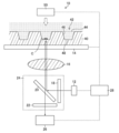
- FIG. 1 is a configuration diagram of an image capturing apparatus 10 according to the present embodiment.
- the image capturing apparatus 10 shown in FIG. 1 is configured to be able to image fluorescence of different wavelengths emitted from cells by one imaging.
- the image pickup apparatus 10 includes a first light source 12 for exciting a fluorescent dye coupled to a cell C, a container 40 having a storage unit 42 for storing the cell C, and a table 14 for mounting the container 40.
- the filter group 24 includes a first multiband pass filter 18, a dichroic mirror 20, and a second multiband pass filter 22.
- the storage portion 42 is formed on the surface of the container 40.
- the container 40 includes three storage units 42. However, the number of storage units 42 is not limited to three, but may be two or less, or four or more.
- the control unit 28 controls imaging by the image capturing apparatus 10.
- the control unit 28 is electrically connected to the table 14, the first light source 12, and the image sensor 26.
- the control unit 28 controls operations of the table 14, the first light source 12, and the image sensor 26.
- the first light source 12, the filter group 24, and the image sensor 26 are arranged on the back side of the container 40. Therefore, the imaging device 10 can capture fluorescence of different wavelengths emitted from the cells C from the back side of the container 40.
- the first light source 12, the filter group 24, and the imaging element 26 may be disposed on the surface side of the container 40 without being limited thereto.
- the imaging device 10 can image a plurality of fluorescence emitted from the cells C from the surface side of the container 40.
- the cell C imaged by the image imaging device 10 is immunostained by an antigen-antibody reaction.
- Antigen-antibody reaction means that an antibody specifically binds to an antigen having a complementary structure.
- Immunostaining means that an antibody linked to a fluorescent dye is bound to an antigen present in a cell.
- Fluorescent dye is excited by excitation light and emits fluorescence.
- the fluorescence emitted by the excitation light has a longer wavelength band than the wavelength band of the excitation light.
- the cell C is bound with at least a plurality of types of fluorescent dyes by immunostaining.
- the plurality of types of fluorescent dyes are excited by excitation light of different wavelength bands, and emit fluorescence of different wavelengths.
- the direct method is a method in which a fluorescent dye is directly bound to an antibody and reacted with an antigen.
- the indirect method does not bind a fluorescent dye to an antibody (primary antibody) that can specifically bind to an antigen to be detected, but does not bind a fluorescent dye to an antibody (secondary antibody) that can specifically bind to the primary antibody. It is the method of detecting by combining.
- cell C is immunostained by antigen-antibody reaction.
- anti-human CD antibody examples include an anti-CD3 antibody, an anti-CD4 antibody, an anti-CD14 antibody, an anti-CD25 antibody, and an anti-CD127 antibody.
- fluorescent dyes 4 ′, 6-diamidine-2′-phenylindole dihydrochloride (DAPI: 4 ′, 6-diamidino-2-phenylindole), propidium iodide (PI), pyronin Y (Pyronin Y), Fluorescein isothiocyanate (FITC), phycoerythrin (PE), allophycocyanin (APC), Texas Red (TR®), Hoechst 33342, 7-amino-actinomycin D (7-amino-actinomycin D) , Cy3 (2′-Deoxycytidine 5′-triphosphoric acid), Cy5 Sulfoindocyanine succinimidyl ester), DRAQ5 (registered trademark) (manufactured by Biostatus Co., Ltd.), mention may be made of Brilliant Violet 570, and Brilliant Violet 421 or the like.
- DAPI 6-diamidine-2′-phenylindole dihydrochloride
- the cells C are stored and held in at least one storage section 42 of the container 40 having a plurality of storage sections 42.
- the storage part 42 is formed by recessing the container 40.
- the storage portion 42 has an opening 44, a side surface 46, and a flat holding surface 48.
- the flat holding surface 48 holds the cell C.
- the side surface 46 of the storage portion 42 has an inclined structure that extends from the holding surface 48 toward the opening 44. By making the side surface 46 have an inclined structure, the cells C can be easily stored in the storage portion 42.
- the holding surface 48 should just be the location where the cell C is hold
- the holding surface 48 of the cell C of the storage unit 42 is flat, it becomes easy to focus on the whole cell when imaging the cell C, and the cell C can be reliably imaged.
- Examples of materials used for the container 40 include polymethacrylic acid esters such as polymethyl methacrylate, polycarbonate, polystyrene, ABS (Acrylonitrile, Butadiene, Styrene copolymer rigid resin), polyethylene terephthalate, aromatic polyester such as polybutylene terephthalate, polypropylene, Various polyolefins such as polycycloolefin, polysulfone, polyethersulfone, polyphenylene sulfide, polylactic acid, thermoplastic rigid resin such as polyperfluoroalkoxy resin, thermosetting rigid resin such as polydimethylsiloxane, and polytetrafluoroethylene Can be used.
- polymethacrylic acid esters such as polymethyl methacrylate, polycarbonate, polystyrene, ABS (Acrylonitrile, Butadiene, Styrene copolymer rigid resin), polyethylene terephthalate, aromatic polyester such as polybutylene terephthal
- the image capturing apparatus 10 includes a table 14 and a driving device (not shown) in order to move the container 40 to an arbitrary position (for example, the X direction, the Y direction, and the Z direction).
- a driving device for example, the X direction, the Y direction, and the Z direction.
- the storage portion 42 that stores the cells C in the container 40 can be moved to the observation position.
- the drive device can move the table 14 in the X direction, the Y direction, and the Z direction.
- the first light source 12 can simultaneously emit light having a plurality of wavelengths. As long as the first light source 12 can simultaneously emit light having a plurality of wavelengths, its structure, method, and the like are not particularly limited.
- the 1st light source 12 is comprised by one light source, and the light of several wavelengths may be light-emitted from one light source.
- the first light source 12 may be configured by a plurality of light sources that emit light having different wavelengths, and light having a plurality of wavelengths may be emitted from the plurality of light sources.
- the term “simultaneously” means that when imaging the cell C, light of a plurality of wavelengths is included, and light of a plurality of wavelengths may be emitted simultaneously or separately.
- the first light source 12 is not particularly limited, and for example, a high pressure mercury lamp, a high pressure xenon lamp, a light emitting diode, a laser diode, a tungsten lamp, a halogen lamp, a white light emitting diode, or the like can be used. Since the first light source 12 can emit light of a plurality of wavelengths simultaneously, it becomes possible to selectively emit excitation light of a plurality of wavelengths that excites a plurality of types of fluorescent dyes in the cell C.
- the filter group 24 includes a first multiband pass filter 18, a dichroic mirror 20, and a second multiband pass filter 22.
- the first multiband pass filter 18 is disposed at an angle of about 90 ° with respect to the traveling direction of the light from the first light source 12 at a position facing the light emission side of the first light source 12.
- the first multiband pass filter 18 functions as an excitation filter.
- the excitation filter is an optical member that selectively transmits light having a wavelength that excites the fluorescent dye among a plurality of wavelengths emitted from the first light source 12 and cuts light having other wavelengths.
- the first multiband pass filter 18 that constitutes the excitation filter includes a plurality of wavelengths of excitation light (at least a plurality of wavelengths of light that are emitted from the first light source 12 and that excites the fluorescent dye coupled to the cell C. Only excitation light of two or more wavelengths) is selectively transmitted.
- the first multiband pass filter 18 can be constituted by, for example, a glass substrate and a dielectric multilayer film having a different refractive index.
- the dichroic mirror 20 is disposed so as to be inclined by about 45 ° with respect to the traveling directions of excitation light having a plurality of wavelengths that have passed through the first multiband pass filter 18.
- the dichroic mirror 20 is configured to reflect excitation light having a plurality of wavelengths and irradiate the cell C.
- the dichroic mirror 20 is configured to transmit fluorescence of different wavelengths emitted by a plurality of types of fluorescent dyes coupled to the cell C excited by excitation light of a plurality of wavelengths. That is, the dichroic mirror 20 is an optical member for separating excitation light and fluorescence.
- the dichroic mirror 20 can be composed of, for example, a glass substrate and a dielectric multilayer film having different refractive indexes.
- the second multi-band pass filter 22 is disposed at an angle of about 90 ° with respect to the traveling directions of the fluorescent light having different wavelengths transmitted through the dichroic mirror 20.
- the second multiband pass filter 22 functions as a fluorescence filter.
- the fluorescence filter is an optical member that transmits only fluorescence in a necessary wavelength band from fluorescence of different wavelengths emitted from the cell C and cuts other light.
- the second multi-band pass filter 22 constituting the fluorescence filter can transmit only the fluorescence of different wavelengths emitted from the cell C without transmitting the excitation light.
- the second multiband pass filter 22 can be constituted by, for example, a glass substrate and a dielectric multilayer film having a different refractive index.
- the objective lens 16 is disposed between the filter group 24 and the cell C in order to collect the excitation light reflected from the dichroic mirror 20 and expand the fluorescence emitted from the cell C.
- a lens used for optical measurement can be used as the objective lens 16 as the objective lens 16.
- the imaging element 26 images fluorescence of different wavelengths that has passed through the second multiband pass filter 22.
- the image sensor 26 is disposed at an angle of about 90 ° with respect to the traveling directions of the fluorescence of different wavelengths that pass through the dichroic mirror 20.
- the image sensor 26 is an electronic device that converts received light into an electrical signal.
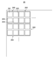
- FIG. 2 is a partially enlarged view of the image sensor 26.
- the imaging element 26 includes a plurality of pixels 260.
- One pixel 260 includes a plurality of subpixels 261, 262, 263, and 264. That is, one pixel 260 is configured by the plurality of subpixels 261, 262, 263, and 264.
- the case where the sizes of the plurality of sub-pixels 261, 262, 263, and 264 are the same is illustrated, but the sizes of the plurality of sub-pixels 261, 262, 263, and 264 are appropriately changed. can do.
- a case where one pixel 260 includes four subpixels 261, 262, 263, and 264 is illustrated, but one pixel 260 may include three subpixels. It may be good and may have five or more subpixels.
- the intensity of fluorescence obtained by the plurality of sub-pixels 261, 262, 263, and 264 of the image sensor 26 is calculated by the control unit 28, and the intensity of fluorescence as one pixel 260 is calculated.
- the image sensor 26 functions as a single-plate color image sensor
- a red filter, a green filter, and a blue filter are arranged on one pixel 260, whereby a plurality of subpixels are arranged on one pixel 260.
- 261, 262, 263, and 264 can be included.
- the red filter, the green filter, and the blue filter are optical filters that transmit only the respective colors.
- the single-plate color image pickup device is an image pickup device that acquires a color image in one image pickup device provided with a red filter, a green filter, and a blue filter.
- a green filter may be arranged in the sub-pixels 261 and 264, a blue filter may be arranged in the sub-pixel 262, and a red filter may be arranged in the sub-pixel 263.
- a red filter may be arranged in the sub-pixel 263.
- the arrangement is not limited to this, and the arrangement can be changed as appropriate.
- an optical filter is shown as an example of constituting a sub-pixel, it is not limited to this.
- a phase difference camera may be used in which diffraction gratings shifted little by little have four subpixels as one pixel.
- the first light source 12 includes a green light emitting diode, a blue light emitting diode, and a purple light emitting diode.
- the cells C are stained with a plurality of types of fluorescent dyes that emit fluorescence of different wavelengths by immunostaining.
- the cells C are stored in the holding surface 48 of at least one storing portion 42 of the container 40 having the plurality of storing portions 42 having the holding surfaces 48 on a flat surface.
- the green light emitting diode, the blue light emitting diode, and the purple light emitting diode constituting the first light source 12 are caused to emit light simultaneously.
- light of a plurality of wavelengths is emitted simultaneously from the first light source 12.
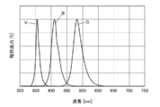
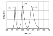
- FIG. 3 is a graph of the spectrum of light of a plurality of wavelengths simultaneously emitted from the first light source 12 with the relative output (%) as the vertical axis and the wavelength (nm) as the horizontal axis.
- the green light emitting diode emits green light G having a peak wavelength in the range of 490 nm to 560 nm.
- the blue light emitting diode emits blue light B having a peak wavelength in the range of 430 nm to 490 nm.
- the violet light emitting diode emits violet light V having a peak wavelength in the range of 380 nm to 430 nm.
- the light of a plurality of wavelengths simultaneously emitted from the first light source 12 is not limited to light of each color emitted from the green light emitting diode, blue light emitting diode, and violet light emitting diode.
- the light having a plurality of wavelengths simultaneously emitted from the first light source 12 can be appropriately selected according to the excitation light with respect to the fluorescent dye coupled to the cell C.
- the relative outputs of the green light G, the blue light B, and the purple light V are constant, but are not limited.
- the control unit 28 independently controls the light amounts of the green light emitting diode, the blue light emitting diode, and the purple light emitting diode.
- the image capturing apparatus 10 can change the intensity of the fluorescence emitted from the cell C as the imaging target, and can capture the fluorescence emitted from the cell C with higher accuracy.
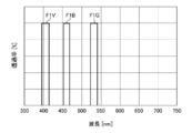
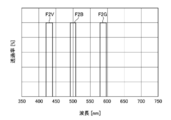
- FIG. 4 is a graph showing a spectral spectrum of the first multiband pass filter 18 with the transmittance (%) as the vertical axis and the wavelength (nm) as the horizontal axis.
- the first multiband pass filter 18 has spectral spectra of F1G, F1B, and F1V that transmit only wavelength bands narrower than the wavelength bands of green light G, blue light B, and violet light V, respectively. And can be configured as a triple bandpass filter.
- the first multiband pass filter 18 transmits excitation light having three wavelengths from among a plurality of wavelengths emitted from the first light source 12.
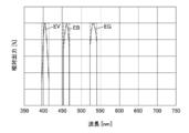
- FIG. 5 is a graph of three excitation light spectra with the relative output (%) as the vertical axis and the wavelength (nm) as the horizontal axis.
- the first multiband pass filter 18 transmits the excitation light EG having a narrower band than the green light G emitted from the green light emitting diode.
- the first multiband pass filter 18 transmits excitation light EB having a narrower band than the blue light B emitted from the blue light emitting diode.
- the first multiband pass filter 18 transmits excitation light EV having a narrower band than the violet light V emitted from the violet light emitting diode.
- FIG. 6 is a graph showing a spectrum of the dichroic mirror 20 with the transmittance (%) as the vertical axis and the wavelength (nm) as the horizontal axis.
- the transmittance in the wavelength band corresponding to the excitation light EG, EB, and EV is set low. For this reason, the plurality of excitation lights EG, EB, and EV are reflected by the dichroic mirror 20 and irradiated toward the cell C.
- the plurality of excitation dyes EG, EB, and EV excite the plurality of types of fluorescent dyes that are coupled to the cell C, so that the plurality of types of fluorescent dyes that are coupled to the cell C emit fluorescence having different wavelengths.
- FIG. 7 shows three fluorescences ⁇ 1G emitted from a plurality of types of fluorescent dyes excited by three excitation lights EG, EB, and EV, with relative output (%) on the vertical axis and wavelength (nm) on the horizontal axis. It is a graph of the spectrum of (lambda) 1B and (lambda) 1V. As shown in FIG. 7, the fluorescence ⁇ 1G, ⁇ 1B, and ⁇ 1V have wavelength bands on the longer wavelength side than the excitation light EG, EB, and EV, respectively.
- Fluorescent light ⁇ 1G, ⁇ 1B, and ⁇ 1V pass through the objective lens 16 and the dichroic mirror 20 having the spectral characteristics shown in FIG. 6 and reach the second multiband filter 22.
- the transmittance in the wavelength bands of the fluorescent light ⁇ 1G, ⁇ 1B, and ⁇ 1V is high. Accordingly, the fluorescences ⁇ 1G, ⁇ 1B, and ⁇ 1V are transmitted through the dichroic mirror 20.
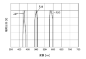
- FIG. 8 is a graph showing the spectrum of the second multiband pass filter 22 with the transmittance (%) as the vertical axis and the wavelength (nm) as the horizontal axis. As shown in FIG.
- the second multiband pass filter 22 includes a spectrum spectrum of F2G, F2B, and F2V that transmits light in a wavelength band narrower than the wavelength bands of fluorescence ⁇ 1G, ⁇ 1B, and ⁇ 1V. Can be configured.
- Fluorescence ⁇ 1G emitted from the cell C and transmitted through the dichroic mirror 20 is transmitted through the second multiband pass filter 22 so that light in an unnecessary wavelength band is cut.
- the fluorescence ⁇ 1B emitted from the cell C and transmitted through the dichroic mirror 20 is transmitted through the second multiband filter 22 so that light in an unnecessary wavelength band is cut.
- the fluorescence ⁇ 1V emitted from the cell C and transmitted through the dichroic mirror 20 is transmitted through the second multiband filter 22 so that light in an unnecessary wavelength band is cut.
- FIG. 9 is a graph of the spectra of fluorescence ⁇ 2G, ⁇ 2B, and ⁇ 2V transmitted through the second multiband pass filter 22 with the relative output (%) as the vertical axis and the wavelength (nm) as the horizontal axis.
- An unnecessary wavelength band of the fluorescence ⁇ 1G is cut by the second multiband pass filter 22, and a fluorescence ⁇ 2G having a narrower wavelength band than the fluorescence ⁇ 1G is output from the second multiband pass filter 22.
- the unnecessary wavelength band of the fluorescence ⁇ 1B is cut by the second multiband pass filter 22, and the fluorescence ⁇ 2B having a narrower wavelength band than the fluorescence ⁇ 1B is output from the second multiband pass filter 22.
- the unnecessary wavelength band of the fluorescence ⁇ 1V is cut by the second multiband pass filter 22, and the fluorescence ⁇ 2V having a narrower wavelength band than the fluorescence ⁇ 1V is output from the second multiband pass filter 22.
- the fluorescence ⁇ 2G, ⁇ 2B, and ⁇ 2V transmitted through the second multiband pass filter 22 are imaged by the imaging element 26 having a plurality of subpixels in one pixel.
- the image sensor 26 can be a single-plate color image sensor that constitutes a sub-pixel with a red filter, a green filter, and a blue filter.
- FIG. 10 is a graph of sensitivity characteristics of the image sensor 26 having a red filter, a green filter, and a blue filter that constitute subpixels, with the relative output (%) as the vertical axis and the wavelength (nm) as the horizontal axis.
- the red filter transmits light in the wavelength band of 555 nm to 700 nm
- the green filter transmits light in the wavelength band of 470 nm to 605 nm
- the blue filter transmits light in the wavelength band of 375 nm to 510 nm.
- transmit can be selected suitably.
- the intensity of the fluorescence imaged by the image sensor 26 is input and stored in the control unit 28, for example.
- the control unit 28 calculates the intensity of the fluorescence and obtains a color image.
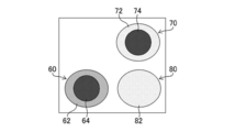
- FIG. 11 is a conceptual diagram of an image of fluorescence emitted from the cell C acquired by the control unit 28 based on the intensity of fluorescence acquired by the image sensor 26.
- white blood cells 60 nucleated red blood cells 70, and red blood cells 80 are displayed.
- the surface 62 emits blue light by the fluorescent dye
- the inner nucleus 64 emits red light by the fluorescent dye.
- the surface 72 emits green light by the fluorescent dye
- the inner nucleus 74 emits red light by the fluorescent dye.
- the surface 82 emits green light by the fluorescent dye.
- the red blood cells 80 do not emit red light because they do not have internal nuclei.
- the imaging time of the cell C can be shortened.
- the image capturing apparatus and image capturing method of the second embodiment shown in FIG. 12 will be described with reference to the drawings.
- the image capturing apparatus 10 is configured to be able to capture a plurality of fluorescence and bright field images from a cell by one image capturing.
- symbol may be attached
- the image pickup apparatus 10 includes a first light source 12 for exciting a fluorescent dye coupled to a cell C, a container 40 having a storage unit 42 for storing the cell C, and a table 14 for mounting the container 40.
- an imaging element 26 for imaging the transmitted light that has passed through the cell C.
- the filter group 24 includes the first multiband pass filter 18, the dichroic mirror 20, and the second multiband pass filter 22 as in the first embodiment.
- the storage portion 42 is formed on the surface of the container 40. In the example of FIG.
- the container 40 has three storage portions 42.
- the number of storage units 42 is not limited to three, but may be two or less, or four or more.
- the second light source 50 is disposed on the front surface side of the container 40, and the first light source 12 is disposed on the back surface side of the container 40. That is, the second light source 50 is disposed on the opposite side of the storage portion 42 formed in the container 40 from the first light source.
- the control unit 28 controls imaging by the image capturing apparatus 10.
- the control unit 28 is electrically connected to the table 14, the first light source 12, the image sensor 26, and the second light source 50.
- the control unit 28 controls operations of the table 14, the first light source 12, the image sensor 26, and the second light source 50.
- the present invention is not limited to this, and fluorescence of different wavelengths emitted from the cell C and a bright field image of the cell C can be captured from the surface side of the container 40.
- the first light source 12 can simultaneously emit light having a plurality of wavelengths. As long as the first light source 12 can simultaneously emit light having a plurality of wavelengths, its structure, method, and the like are not particularly limited.
- the first light source 12 preferably includes two light emitting diodes selected from the group of green light emitting diodes, blue light emitting diodes, and purple light emitting diodes. By emitting light having different wavelengths from the two light emitting diodes, fluorescence having two different wavelengths can be emitted from the fluorescent dye bound to the cell C.
- the second light source 50 is not particularly limited in its structure, method, and the like as long as it can emit excitation light that excites the fluorescent dye of the cell C and light having a wavelength different from the fluorescence emitted from the fluorescent dye.
- a high pressure mercury lamp, a high pressure xenon lamp, a light emitting diode, a laser diode, a tungsten lamp, a halogen lamp, a white light emitting diode etc. can be used.
- the wavelength band of the light emitted from the second light source 50 includes the same wavelength as the excitation light for exciting the fluorescent dye of the cell C or the fluorescence emitted from the fluorescent dye, a band is formed between the cell C and the second light source 50.
- the cell C can be irradiated with excitation light that excites the fluorescent dye of the cell C and light having a wavelength different from the fluorescence emitted from the fluorescent dye.
- the filter group 24 includes a first multiband pass filter 18, a dichroic mirror 20, and a second multiband pass filter 22.
- the first multiband pass filter 18 functions as an excitation filter that is an optical member
- the dichroic mirror 20 functions as an optical member for separating excitation light and fluorescence
- the second multiband pass filter 22 is an optical member. Functions as a fluorescent filter.
- the dichroic mirror 20 and the second multiband pass filter 22 transmit the transmitted light that is irradiated from the second light source 50 and transmitted through the cells C.
- the transmitted light from the second light source 50 that has passed through the cells C constitutes a bright field image.
- a phase difference condenser (a donut-shaped slit) is disposed immediately before the second light source 50, which is a transmitted light source, and the objective lens is changed to a phase difference observation lens to add a phase difference observation lens. It can also be acquired as a phase difference image.
- the objective lens 16 is disposed between the filter group 24 and the cell C in order to collect the excitation light irradiated from the dichroic mirror 20 and to expand the fluorescence emitted from the cell C and the transmitted light.
- a lens used for optical measurement can be used as the objective lens 16.
- the imaging device 26 images fluorescence of different wavelengths and transmitted light of one wavelength transmitted through the second multiband pass filter 22.
- the image sensor 26 can have the same configuration as in the first embodiment, and includes a plurality of pixels 260 as shown in FIG.
- One pixel 260 includes a plurality of subpixels 261, 262, 263, and 264. That is, one pixel 260 is configured by the plurality of subpixels 261, 262, 263, and 264.
- the sizes of the plurality of subpixels 261, 262, 263, and 264 may be changed as appropriate.
- one pixel 260 may have three subpixels, or may have five or more subpixels.
- the first light source 12 is a light source including a blue light emitting diode and a purple light emitting diode
- the second light source 50 is a red light emitting diode.
- the cells C are stained with a fluorescent dye and held on the holding surface 48.
- the blue light emitting diode and the purple light emitting diode constituting the first light source 12 are caused to emit light at the same time, thereby simultaneously emitting light of a plurality of wavelengths from the first light source 12.
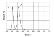
- FIG. 13 is a graph of the spectrum of light of a plurality of wavelengths simultaneously emitted from the first light source 12, with the relative output (%) as the vertical axis and the wavelength (nm) as the horizontal axis.
- the blue light emitting diode emits blue light B having a peak wavelength of 470 nm.
- the purple light emitting diode emits purple light V having a peak wavelength of 405 nm.
- the light of a plurality of wavelengths simultaneously emitted from the first light source 12 is not limited to light of each color emitted from the blue light emitting diode and the violet light emitting diode. It is possible to select appropriately according to the excitation light for the fluorescent dye bound to the cell C.
- control unit 28 can independently control the light amounts of the blue light emitting diode and the purple light emitting diode.
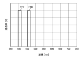
- FIG. 14 is a graph showing a spectrum of the first multiband pass filter 18 with the transmittance (%) as the vertical axis and the wavelength (nm) as the horizontal axis.
- the first multiband pass filter 18 includes F1B and F1V spectral spectra that transmit only the wavelength bands narrower than the wavelength bands of the blue light B and the violet light V, respectively. Can be configured as a filter. Note that there may be a spectrum of green light F1G as shown in FIG.
- the first multiband pass filter 18 transmits excitation light having two wavelengths from among a plurality of wavelengths emitted from the first light source 12.
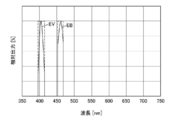
- FIG. 15 is a graph of two excitation light spectra with the relative output (%) as the vertical axis and the wavelength (nm) as the horizontal axis.
- the first multiband pass filter 18 transmits excitation light EB having a narrower band than the blue light B emitted from the blue light emitting diode.
- the first multiband pass filter 18 transmits excitation light EV having a narrower band than the violet light V emitted from the violet light emitting diode.
- FIG. 16 is a graph showing a spectrum of the dichroic mirror 20 with the transmittance (%) as the vertical axis and the wavelength (nm) as the horizontal axis.
- the plurality of excitation light EB and EV are dichroic. The light is reflected by the mirror 20 and irradiated toward the cell C. Note that there may be a region that does not transmit light at 520 nm to 550 nm as shown in FIG.
- FIG. 17 shows two excitation lights EB having a relative output (%) on the vertical axis and a wavelength (nm) on the horizontal axis, and fluorescence ⁇ 1B and ⁇ 1V emitted from a plurality of types of fluorescent dyes excited by EV, 4 is a graph of a spectrum of transmitted light R from a second light source 50.
- the fluorescent light ⁇ 1B and ⁇ 1V have wavelength bands on the longer wavelength side than the excitation light EB and EV, respectively.
- the transmitted light R from the second light source 50 has a wavelength band different from the fluorescence ⁇ 1B and ⁇ 1V. Since the transmitted light R and the fluorescent lights 1 ⁇ B and ⁇ 1V have different wavelength bands, two fluorescent lights and one transmitted light can be imaged by the imaging device 26 as described later.
- the fluorescent light ⁇ 1B and ⁇ 1V and the transmitted light R pass through the objective lens 16 and the dichroic mirror 20 having the spectral characteristics shown in FIG. 16 and reach the second multiband filter 22.
- the transmittance in the wavelength band of the fluorescent light ⁇ 1B, ⁇ 1V and the transmitted light R is high. Therefore, the fluorescent light ⁇ 1B, ⁇ 1V and the transmitted light R are transmitted through the dichroic mirror 20.
- FIG. 18 is a graph showing the spectrum of the second multiband pass filter 22 with the transmittance (%) as the vertical axis and the wavelength (nm) as the horizontal axis. As shown in FIG.
- the second multiband pass filter 22 has a spectral band of F2B, F2V, and FR that transmits only fluorescence ⁇ 1B and ⁇ 1V and a wavelength band narrower than the wavelength band of transmitted light R, and a triple bandpass.
- Fluorescence ⁇ 1B emitted from the cell C and transmitted through the dichroic mirror 20 is transmitted through the second multiband pass filter 22 so that light in an unnecessary wavelength band is cut.
- the fluorescence ⁇ 1V emitted from the cell C and transmitted through the dichroic mirror 20 is transmitted through the second multiband filter 22 so that light in an unnecessary wavelength band is cut.
- the transmitted light R that has passed through the cell C and the dichroic mirror 20 is transmitted through the second multiband pass filter 22 so that light in an unnecessary wavelength band is cut.
- FIG. 19 is a graph of the spectrum of fluorescence and transmitted light transmitted through the second multiband pass filter 22 with the relative output (%) as the vertical axis and the wavelength (nm) as the horizontal axis.
- An unnecessary wavelength band of the fluorescence ⁇ 1B is cut by the second multiband pass filter 22, and a fluorescence ⁇ 2B having a narrower wavelength band than the fluorescence ⁇ 1B is output from the second multiband pass filter 22.
- the unnecessary wavelength band of the fluorescence ⁇ 1V is cut by the second multiband pass filter 22, and the fluorescence ⁇ 2V having a narrower wavelength band than the fluorescence ⁇ 1V is output from the second multiband pass filter 22.
- the unnecessary wavelength band of the transmitted light R is cut by the second multiband pass filter 22, and the transmitted light ⁇ R having a narrower wavelength band than the transmitted light R is output from the second multiband pass filter 22.
- the fluorescence ⁇ 2B and ⁇ 2V transmitted through the second multiband pass filter 22 and the transmitted light ⁇ R are imaged by the imaging element 26 having a plurality of subpixels in one pixel.
- the image sensor 26 a single plate type color image sensor having a red filter, a green filter and a blue filter similar to those of the first embodiment can be used.
- the intensity of the fluorescence imaged by the image sensor 26 and the intensity of the transmitted light are input to the control unit 28 and stored, for example.
- the control unit 28 calculates the intensity of fluorescence and the intensity of transmitted light, and acquires a color image.
- FIG. 20 is a conceptual diagram of fluorescence and phase difference image images emitted from the cells C acquired by the control unit 28 based on the fluorescence intensity acquired by the image sensor 26.
- nucleated red blood cells 70 are displayed.
- the fluorescence of the young erythrocyte may fluoresce locally without being uniformly fluoresced throughout the erythrocyte.
- the shape of the nucleated red blood cell 70 cannot be grasped by fluorescence.
- a bright-field image is preferable because the grasp of the shape becomes clearer by obtaining a phase difference image.
- the nucleus 74 in the nucleated red blood cell 70 emits blue light by, for example, a fluorescent dye
- the HbF 76 fetal hemoglobin
- the outer shape 79 of the nucleated red blood cell 70 a phase difference image is taken using transmitted light.
- the imaging time of the cell C can be shortened. Can do.
Landscapes
- Physics & Mathematics (AREA)
- Health & Medical Sciences (AREA)
- General Physics & Mathematics (AREA)
- Life Sciences & Earth Sciences (AREA)
- Chemical & Material Sciences (AREA)
- Immunology (AREA)
- Spectroscopy & Molecular Physics (AREA)
- Analytical Chemistry (AREA)
- Biochemistry (AREA)
- Pathology (AREA)
- General Health & Medical Sciences (AREA)
- Nuclear Medicine, Radiotherapy & Molecular Imaging (AREA)
- Engineering & Computer Science (AREA)
- Hematology (AREA)
- Optics & Photonics (AREA)
- Biomedical Technology (AREA)
- Urology & Nephrology (AREA)
- Molecular Biology (AREA)
- Chemical Kinetics & Catalysis (AREA)
- Food Science & Technology (AREA)
- Medicinal Chemistry (AREA)
- Microbiology (AREA)
- Cell Biology (AREA)
- Biotechnology (AREA)
- Investigating, Analyzing Materials By Fluorescence Or Luminescence (AREA)
- Investigating Or Analysing Biological Materials (AREA)
Abstract
細胞から発光される複数の蛍光を撮像する時間を短くすることができる画像撮像装置及び画像撮像方法を提供する。画像撮像装置は、異なる波長の蛍光を発光する複数種の蛍光色素で染色された細胞を平坦な保持面で保持して収納する少なくとも一つの収納部と、複数の波長の光を同時に発光する第1光源と、第1光源から発光される複数の波長の光のうち複数種の蛍光色素を励起する複数の波長の励起光を透過させる第1マルチバンドパスフィルターと、第1マルチバンドパスフィルターを透過した複数の波長の励起光を細胞に向けて照射させ複数の波長の励起光により細胞から発光される異なる波長の蛍光を透過させるダイクロイックミラーと、ダイクロイックミラーを透過した異なる波長の蛍光を透過させる第2マルチバンドパスフィルターと、を含むフィルター群と、複数の波長の励起光を集光し異なる波長の蛍光を拡大させる対物レンズと、第2マルチバンドパスフィルターを透過した異なる波長の蛍光を撮像する1画素に複数の副画素を有する撮像素子と、を有する。
Description
本発明は画像撮像装置及び画像撮像方法に関する。
免疫染色により複数の蛍光色素が結合された細胞を観察するため、蛍光顕微鏡等が画像撮像装置として使用されている。
特許文献1には、レーザ光源の光をマイクロレンズにより集光し、ダイクロイックミラーにより任意の波長の光を励起光として透過させ、ピンホールを介して励起光を試料に照射し、試料からの蛍光をCCD(charge-coupled device)カメラで撮像することが記載されている。
また、特許文献2には、試料から発光される複数種類の蛍光を、透過光の波長帯域が可変である波長可変液晶分光フィルターを透過させ、検出器により撮像することが記載されている。
ところで、試料から発光される蛍光を撮像する画像撮像装置には、時間を短縮する観点から1回の撮影により異なる波長の蛍光を撮像することが求められている。
しかしながら、特許文献1には、蛍光を撮像するための撮像素子の具体的な構成を開示していない。また、特許文献2では、波長可変液晶分光フィルターを透過光の波長域を可変させながら、撮像しており、1回の撮影で異なる波長の蛍光を撮像することも1回の撮影で異なる波長の蛍光を撮像する撮像素子の具体的な構成も開示していない。
本発明は、このような事情に鑑みてなされたもので、1回の撮影により、細胞からの複数の蛍光を撮像することのできる画像撮像装置、及び画像撮像方法を提供することを目的とする。また、1回の撮影により、細胞からの複数の蛍光と細胞からの透過光を撮像することのできる画像撮像装置、及び画像撮像方法を提供することを目的とする。
本発明の一態様によると、画像撮像装置は、異なる波長の蛍光を発光する複数種の蛍光色素で染色された細胞を平坦な保持面で保持して収納する少なくとも一つの収納部と、複数の波長の光を同時に発光する第1光源と、第1光源から発光される複数の波長の光のうち複数種の蛍光色素を励起する複数の波長の励起光を選択的に透過させる第1マルチバンドパスフィルターと、第1マルチバンドパスフィルターを透過した複数の波長の励起光を細胞に向けて照射させ複数の波長の励起光により細胞から発光される異なる波長の蛍光を透過させるダイクロイックミラーと、ダイクロイックミラーを透過した異なる波長の蛍光を透過させる第2マルチバンドパスフィルターと、を含むフィルター群と、複数の波長の励起光を集光し異なる波長の蛍光を拡大させる対物レンズと、第2マルチバンドパスフィルターを透過した異なる波長の蛍光を撮像する1画素に複数の副画素を有する撮像素子と、を有する。
好ましくは、撮像素子がカラー撮像素子である。
好ましくは、カラー撮像素子が、赤色フィルター、緑色フィルター、及び青色フィルターを有する単板式の撮像素子である。
好ましくは、第1光源と、フィルター群と、撮像素子とが、収納部に対して保持面とは反対の側に配置される。
好ましくは、第1マルチバンドパスフィルター、及び第2マルチバンドパスフィルターは、トリプルバンドパスフィルターで構成される。
好ましくは、第1光源は、複数の光源により構成される。
好ましくは、複数の光源の光量を、それぞれ独立に制御する制御部を有する。
好ましくは、第1光源が、少なくとも緑色発光ダイオード、青色発光ダイオード、及び紫色発光ダイオードを含む光源である。
好ましくは、収納部は、複数の収納部を有する容器の一つの収納部である。
本発明の別の態様によると、画像撮像装置は、異なる波長の蛍光を発光する複数種の蛍光色素で染色された細胞を平坦な保持面で保持して収納する少なくとも一つの収納部と、複数の波長の光を同時に発光する第1光源と、収納部に対して第1光源とは反対の側に配置された、一つの波長の透過光を発光する第2光源と、第1光源から発光される複数の波長の光のうち複数種の蛍光色素を励起する複数の波長の励起光を選択的に透過させる第1マルチバンドパスフィルターと、第1マルチバンドパスフィルターを透過した複数の波長の励起光を細胞に向けて照射させ複数の波長の励起光により細胞から発光される複数の異なる波長の蛍光を透過させかつ第2光源から発光される一つの波長の透過光を透過させるダイクロイックミラーと、ダイクロイックミラーを透過した異なる波長の蛍光及び一つの波長の透過光を透過させる第2マルチバンドパスフィルターと、を含むフィルター群と、複数の波長の励起光を集光し異なる波長の蛍光及び透過光を拡大させる対物レンズと、第2マルチバンドパスフィルターを透過した異なる波長の蛍光と一つの波長の透過光を撮像する1画素に複数の副画素を有する撮像素子と、を有する。
好ましくは、第1光源が、緑色発光ダイオード、青色発光ダイオード、及び紫色発光ダイオードの群から選択される2つの発光ダイオードを含む。
本発明の別の態様によると、画像撮像方法は、異なる波長の蛍光を発光する複数種の蛍光色素で染色された細胞を平坦な表面に保持する保持面を有する少なくとも一つの収納部に収納するステップと、第1光源から複数の波長の光を同時に発光するステップと、第1光源から発光される複数の波長の光のうち複数種の蛍光色素を励起する複数の波長の励起光を第1マルチバンドパスフィルターに選択的に透過させ、ダイクロイックミラーにより第1マルチバンドパスフィルターを透過した複数の波長の励起光を細胞に向けて照射させ、複数の波長の励起光により細胞から発光される異なる波長の蛍光を第1マルチバンドパスフィルターを透過させ、第1マルチバンドパスフィルターを透過した異なる波長の蛍光を第2マルチバンドパスフィルターを透過させるステップと、第2マルチバンドパスフィルターを透過した異なる波長の蛍光を1画素に複数の副画素を有する撮像素子により撮像するステップと、を有する。
本発明の別の態様によると、画像撮像方法は、異なる波長の蛍光を発光する複数種の蛍光色素で染色された細胞を平坦な表面に保持する保持面を有する少なくとも一つの収納部に収納するステップと、第1光源から複数の波長の光を同時に発光し、収納部に対して第1光源と反対の側に配置される第2光源から一つの波長の透過光を発光するステップと、第1光源から発光される複数の波長の光のうち複数種の蛍光色素を励起するの複数の波長の励起光を第1マルチバンドパスフィルターに選択的に透過し、ダイクロイックミラーにより第1マルチバンドパスフィルターを透過した複数の波長の励起光を細胞に向けて照射させ、複数の波長の励起光により細胞から発光される異なる波長の蛍光と第2光源から発光される一つの波長の透過光とをダイクロイックミラーを透過させ、ダイクロイックミラーを透過した異なる波長の蛍光と第2光源から発光される一つの波長の透過光とを第2マルチバンドパスフィルターを透過させるステップと、第2マルチバンドパスフィルターを透過した異なる波長の蛍光と第2光源から発光される一つの波長の透過光とを1画素に複数の副画素を有する撮像素子により撮像するステップと、を有する。
本発明の一態様によれば、1回の撮影により、細胞からの複数の蛍光を撮像することができ、試料から発光される蛍光を撮像する時間を短縮できる。
また、本発明の別の態様によれば、1回の撮影により、細胞からの複数の蛍光と細胞の透過光とを撮像することができ、試料から発光される蛍光を撮像する時間を短縮できる。
以下、添付図面にしたがって本発明の好ましい実施形態について説明する。本発明は以下の好ましい実施形態により説明される。本発明の範囲を逸脱すること無く、多くの手法により変更を行うことができ、実施形態以外の他の実施形態を利用することができる。したがって、本発明の範囲内における全ての変更が請求の範囲に含まれる。
ここで、図中、同一の記号で示される部分は、同様の機能を有する同様の要素である。また、本明細書中で、数値範囲を“ ~ ”を用いて表す場合は、“ ~ ”で示される上限、下限の数値も数値範囲に含むものとする。
(第1実施形態)
第1実施形態の画像撮像装置、及び画像撮像方法について、図面を参照して説明する。図1は、本実施形態の画像撮像装置10の構成図である。図1に示される、画像撮像装置10は、1回の撮影により、細胞から発光される異なる波長の蛍光を撮像することができるよう構成される。
第1実施形態の画像撮像装置、及び画像撮像方法について、図面を参照して説明する。図1は、本実施形態の画像撮像装置10の構成図である。図1に示される、画像撮像装置10は、1回の撮影により、細胞から発光される異なる波長の蛍光を撮像することができるよう構成される。
画像撮像装置10は、細胞Cに結合された蛍光色素を励起するための第1光源12と、細胞Cを収納する収納部42を有する容器40と、容器40を載置するためのテーブル14と、フィルター群24と、細胞Cとフィルター群24との間に配置された対物レンズ16と、細胞Cから発光される蛍光を撮像するための撮像素子26と、を備える。フィルター群24は、第1マルチバンドパスフィルター18、ダイクロイックミラー20及び第2マルチバンドパスフィルター22を含む。また、収納部42は、容器40の表面に形成される。また、図1の例では、容器40は、3つの収納部42を有する。ただし、収納部42の数は3つに限らず、2つ以下でも良いし、4つ以上でも良い。
制御部28は、画像撮像装置10による撮像を制御する。制御部28は、テーブル14、第1光源12及び撮像素子26と電気的に接続されている。制御部28は、テーブル14、第1光源12及び撮像素子26の動作を制御する。
本実施形態においては、第1光源12と、フィルター群24と、撮像素子26とは、容器40の裏面側に配置される。したがって、撮像装置10は、細胞Cから発光される異なる波長の蛍光を、容器40の裏面側から撮像することが可能である。
但し、これに限定されることなく、第1光源12と、フィルター群24と、撮像素子26とは、容器40の表面側に配置されても良い。この場合、撮像装置10は、細胞Cから発光される複数の蛍光を、容器40の表面側から撮像することが可能である。
画像撮像装置10により撮像される細胞Cは、抗原抗体反応により免疫染色されている。抗原抗体反応とは、抗体が相補的な構造を持つ抗原と特異的に結合することを意味する。免疫染色とは、細胞に存在する抗原に、蛍光色素を連結した抗体を結合させることを意味する。
蛍光色素は、励起光により励起され蛍光を発光する。なお、励起光により発光する蛍光は、励起光の波長帯域に比べてより長波長側の波長帯域を有する。
本実施形態においては、細胞Cは、免疫染色により、少なくとも複数種の蛍光色素が結合されている。複数種の蛍光色素は、それぞれ異なる波長帯域の励起光により励起され、それぞれ異なる波長の蛍光を発光する。
免疫染色には、直接法と間接法とがある。直接法は、蛍光色素を直接抗体に結合し、抗原と反応させる方法である。一方、間接法は、検出すべき抗原に特異的に結合できる抗体(1次抗体)には蛍光色素を結合せず、その1次抗体に特異的に結合できる抗体(2次抗体)に蛍光色素を結合して検出する方法である。
上述したように、細胞Cは、抗原抗体反応により免疫染色される。例えば、抗ヒトCD抗体として、抗CD3抗体、抗CD4抗体、抗CD14抗体、抗CD25抗体、抗CD127抗体等を例示することができる。蛍光色素として、4’,6-ジアミジン-2’-フェニルインドールジハイドロクロライド(DAPI:4‘,6-diamidino-2-phenylindole)、ヨウ化プロピジウム(PI:PropidiumIodide)、ピロニンY(Pyronin Y)、フルオレセインイソチオシアネート(FITC:fluoresceinisothiocyanate)、フィコエリスリン(PE:phycoerythrin)、アロフィコシアニン(APC:allophicocyanin)、テキサスレッド(TR(登録商標))、Hoechst33342、7-アミノ-アクチノマイシンD(7-AAD)、Cy3(2‘-Deoxycytidine 5’-triphosphoric acid)、Cy5(Sulfoindocyanine succinimidyl ester)、DRAQ5(登録商標)(Biostatus社製)、Brilliant Violet 570、及びBrilliant Violet 421等を挙げることができる。
細胞Cは、複数の収納部42を有する容器40の少なくとも一つの収納部42に収納され保持される。収納部42は、容器40を凹設して形成されている。収納部42は、開口44と側面46と平坦な保持面48を有している。平坦な保持面48は、細胞Cを保持する。収納部42の側面46は、保持面48から開口44に向かって広がる傾斜構造である。側面46を傾斜構造とすることにより、細胞Cを収納部42内に容易に収納させることができる。なお、保持面48は、細胞Cを保持する箇所が平坦であれば良い。
収納部42の細胞Cの保持面48が平坦であるので、細胞Cを撮像する際に、細胞全体に焦点を合わせることが容易となり、細胞Cの撮像を確実に行うことが可能となる。
容器40に用いられる材料としては、ポリメチルメタクリレートなどのポリメタクリル酸エステル、ポリカーボネート、ポリスチレン、ABS(Acrylonitrile、Butadiene、Styrene共重合剛性樹脂)、ポリエチレンテレフタレート、ポリブチレンテレフタレートなどの芳香族ポリエステル、ポリプロピレン、ポリシクロオレフィンなどの各種ポリオレフィン、ポリスルホン、ポリエーテルスルホン、ポリフェニレンサルファイド、ポリ乳酸、ポリパーフルオロアルコキシ樹脂のような熱可塑性剛性樹脂、ポリジメチルシロキサンなどの熱硬化性剛性樹脂、及びポリテトラフルオロエチレン等を用いることが可能である。
本実施形態の画像撮像装置10は、容器40を任意の位置に移動(例えば、X方向、Y方向、及びZ方向)させるため、テーブル14と駆動装置(不図示)とを備えていることが好ましい。テーブル14と駆動装置とにより、容器40の細胞Cを収納する収納部42を、観察位置に移動させることができる。駆動装置は、テーブル14を、X方向、Y方向、及びZ方向に移動できることが好ましい。
第1光源12は、複数の波長の光を同時に発光することができる。第1光源12は、複数の波長の光を同時に発光することができれば、その構造、方式等は特に限定されない。第1光源12は、1個の光源により構成され、1個の光源から複数の波長の光が発光されても良い。第1光源12が波長の異なる光を発光する複数の光源により構成され、複数の光源から複数の波長の光が発光されても良い。また、同時とは、細胞Cを撮像する際に、複数の波長の光が含まれていることを意味し、複数の波長の光が同時に発光されても、別々に発光されても良い。
第1光源12として、特に限定されないが、例えば、高圧水銀ランプ、高圧キセノンランプ、発光ダイオード、レーザダイオード、タングステンランプ、ハロゲンランプ、及び白色発光ダイオード等を用いることができる。第1光源12が複数の波長の光を同時に発光することができるので、細胞Cの複数種の蛍光色素を励起する複数の波長の励起光を選択的に発光することが可能となる。
フィルター群24は、第1マルチバンドパスフィルター18、ダイクロイックミラー20及び第2マルチバンドパスフィルター22を含んでいる。
第1マルチバンドパスフィルター18は、第1光源12の発光側に対向する位置において、第1光源12からの光の進行方向に対して約90°傾けられて配置される。第1マルチバンドパスフィルター18は、励起フィルターとして機能する。励起フィルターは、第1光源12から発光される複数の波長の光のうち蛍光色素を励起する波長の光を選択的に透過させ、その他の波長の光をカットする光学部材である。
励起フィルターを構成する第1マルチバンドパスフィルター18は、第1光源12から発光される複数の波長の光の中から、細胞Cに結合された蛍光色素を励起する複数の波長の励起光(少なくとも2以上の波長の励起光)のみを選択的に透過するよう構成される。第1マルチバンドパスフィルター18は、例えば、ガラス基板と、屈折率の異なる誘電体の多層膜とにより構成することが可能である。
ダイクロイックミラー20は、第1マルチバンドパスフィルター18を透過した複数の波長の励起光の進行方向に対して約45°傾けられて配置される。ダイクロイックミラー20は、複数の波長の励起光を反射し、細胞Cに向けて照射するよう構成される。また、ダイクロイックミラー20は、複数の波長の励起光により励起された細胞Cに結合された複数種の蛍光色素が発光する異なる波長の蛍光を透過するよう構成される。すなわち、ダイクロイックミラー20は、励起光と蛍光とを分離するための光学部材である。
励起光により発光する蛍光は、励起光の波長帯域に比べて、長波長側の波長帯域を有するので、ダイクロイックミラー20を使用することにより、蛍光のみを透過させることが可能となる。ダイクロイックミラー20は、例えば、ガラス基板と、屈折率の異なる誘電体の多層膜とにより構成することが可能である。
第2マルチバンドパスフィルター22は、ダイクロイックミラー20を透過した異なる波長の蛍光の進行方向に対して約90°に傾けられて配置される。第2マルチバンドパスフィルター22は、蛍光フィルターとして機能する。蛍光フィルターは、細胞Cから発光される異なる波長の蛍光から必要な波長帯域の蛍光のみを透過し、その他の光をカットする光学部材である。
蛍光フィルターを構成する第2マルチバンドパスフィルター22は、励起光を透過させず、細胞Cから発光される異なる波長の蛍光のみを透過させることが可能である。第2マルチバンドパスフィルター22は、例えば、ガラス基板と、屈折率の異なる誘電体の多層膜とにより構成することが可能である。
対物レンズ16は、ダイクロイックミラー20から反射される励起光を集光し、かつ細胞Cから発光される蛍光を拡大させるため、フィルター群24と細胞Cとの間に配置される。対物レンズ16として、光学測定に使用されるレンズを用いることができる。
撮像素子26は、第2マルチバンドパスフィルター22を透過した異なる波長の蛍光を撮像する。撮像素子26は、ダイクロイックミラー20を透過する異なる波長の蛍光の進行方向に対して約90°傾けられて配置される。撮像素子26は、受光した光を電気信号に変換する電子デバイスである。
図2は、撮像素子26の部分拡大図である。撮像素子26は、図2に示されるように、複数の画素260を含んでいる。1個の画素260は、複数の副画素261、262、263、及び264を有している。すなわち、複数の副画素261、262、263、及び264により1個の画素260が構成される。
本実施形態では、複数の副画素261、262、263、及び264の大きさが同じ大きさである場合を例示したが、複数の副画素261、262、263、及び264の大きさを適宜変更することができる。また、本実施形態では、1個の画素260は、4つの副画素261、262、263、及び264を有する場合を例示したが、1個の画素260は、3つの副画素を有しても良いし、5つ以上の副画素を有しても良い。
撮像素子26の複数の副画素261、262、263、及び264により得られた蛍光の強度は、制御部28により演算処理され、1個の画素260としての蛍光の強度が算出される。
例えば、撮像素子26を単板式のカラー撮像素子として機能させる場合、1個の画素260の上に赤色フィルター、緑色フィルター、及び青色フィルターを配列することにより、1個の画素260に複数の副画素261、262、263、及び264を含ませることができる。赤色フィルター、緑色フィルター、及び青色フィルターは、それぞれの色のみを透過させる光学フィルターである。単板式のカラー撮像素子とは、赤色フィルター、緑色フィルター、及び青色フィルターを設けた1個の撮像素子において、カラー画像を取得する撮像素子である。
赤色フィルター、緑色フィルター、及び青色フィルターを配列する際、例えば、副画素261、及び264に緑色フィルターを配列し、副画素262に青色フィルターを配列し、副画素263に赤色フィルターを配列することが好ましい。但し、これに限定されず、配列は適宜変更が可能である。
副画素を構成する例として光学フィルターを示したが、これに限定されない。例えば、位相差画像を撮像するため、少しずつずらした回折格子を4個の副画素を1画素とする位相差カメラであっても良い。
次に、上述のように構成された画像撮像装置10による画像撮像方法について、第1光源12が、緑色発光ダイオード、青色発光ダイオード、及び紫色発光ダイオードから構成される場合を例に説明する。
まず、細胞Cは、免疫染色により異なる波長の蛍光を発光する複数種の蛍光色素で染色される。次に、収納するステップでは、細胞Cは、平坦な表面に保持面48を有する複数の収納部42を有する容器40の少なくとも1個の収納部42の保持面48に収納される。
次に、発光するステップでは、第1光源12を構成する緑色発光ダイオード、青色発光ダイオード、及び紫色発光ダイオードを同時に発光させる。これにより、第1光源12から複数の波長の光を同時に発光させる。
図3は、相対出力(%)を縦軸、波長(nm)を横軸とする、第1光源12から同時に発光される複数の波長の光のスペクトルのグラフである。緑色発光ダイオードは490nm以上560nm以下の範囲にピーク波長を有する緑色光Gを発光する。また、青色発光ダイオードは430nm以上490nm以下の範囲にピーク波長を有する青色光Bを発光する。また、紫色発光ダイオードは380nm以上430nm以下の範囲にピーク波長を有する紫色光Vを発光する。
第1光源12から同時に発光される複数の波長の光は、緑色発光ダイオード、青色発光ダイオード、及び紫色発光ダイオードから発光される各色の光に限定されない。第1光源12から同時に発光される複数の波長の光は、細胞Cに結合される蛍光色素に対する励起光に応じて適宜選択することが可能である。
本実施形態では、緑色光G、青色光B、及び紫色光Vの相対出力は、一定とされているが、限定されない。例えば、制御部28は、緑色発光ダイオード、青色発光ダイオード、及び紫色発光ダイオードの光量を、それぞれ独立に制御する。これにより、画像撮像装置10は、撮像対象である細胞Cから発光される蛍光の強度を変更でき、細胞Cから発光される蛍光をより精度良く撮像できる。
次に、第1光源12から発光される複数の波長の光のうち細胞Cに結合される蛍光色素を励起する複数の波長の励起光は、第1マルチバンドパスフィルター18を透過する。図4は、透過率(%)を縦軸、波長(nm)を横軸とする、第1マルチバンドパスフィルター18の分光スペクトルを示すグラフである。図4に示されるように、第1マルチバンドパスフィルター18は、緑色光G、青色光B、及び紫色光Vそれぞれの波長帯域より狭い波長帯域のみを透過させるF1G、F1B、及びF1Vの分光スペクトルを備え、トリプルバンドパスフィルターとして構成することができる。
第1マルチバンドパスフィルター18は、第1光源12から発光される複数の波長の光の中から、3つの波長の励起光を透過する。図5は、相対出力(%)を縦軸、波長(nm)を横軸とする、3つの励起光のスペクトルのグラフである。第1マルチバンドパスフィルター18は、緑色発光ダイオードから照射される緑色光Gより狭帯域の励起光EGを透過させる。また、第1マルチバンドパスフィルター18は、青色発光ダイオードから照射される青色光Bより狭帯域の励起光EBを透過させる。また、第1マルチバンドパスフィルター18は、紫色発光ダイオードから照射される紫色光Vより狭帯域の励起光EVを透過させる。
図6は、透過率(%)を縦軸、波長(nm)を横軸とする、ダイクロイックミラー20の分光スペクトルを示すグラフである。図6に示されるように、ダイクロイックミラー20の分光特性によれば、励起光EG、EB、及びEVに対応する波長帯域の透過率が低く設定されている。このため、複数の励起光EG、EB、及びEVは、ダイクロイックミラー20により反射され、細胞Cに向けて照射される。
複数の励起光EG、EB、及びEVが、細胞Cに結合された複数種の蛍光色素を励起することにより、細胞Cに結合された複数種の蛍光色素が異なる波長の蛍光を発光する。図7は、相対出力(%)を縦軸、波長(nm)を横軸とする、3つの励起光EG、EB及びEVにより励起された複数種の蛍光色素から発光される3つの蛍光λ1G、λ1B及びλ1Vのスペクトルのグラフである。図7に示されるように、蛍光λ1G、λ1B及びλ1Vは、それぞれ、励起光EG、EB及びEVより長波長側の波長帯域を有する。
蛍光λ1G、λ1B及びλ1Vは、対物レンズ16、及び図6に示される分光特性を有するダイクロイックミラー20を透過し、第2マルチバンドパスフィルター22に到達する。ここで、図6に示されるとおり、ダイクロイックミラー20の分光特性によれば、蛍光λ1G、λ1B及びλ1Vの波長帯域の透過率が高い。したがって、蛍光λ1G、λ1B及びλ1Vは、ダイクロイックミラー20を透過する。図8は、透過率(%)を縦軸、波長(nm)を横軸とする、第2マルチバンドパスフィルター22の分光スペクトルを示すグラフである。図8に示されるように、第2マルチバンドパスフィルター22は、蛍光λ1G、λ1B及びλ1Vの波長帯域より狭い波長帯域の光を透過させるF2G、F2B及びF2Vの分光スペクトルを備え、トリプルバンドパスフィルターとして構成することができる。
細胞Cから発光されダイクロイックミラー20を透過した蛍光λ1Gは、第2マルチバンドパスフィルター22を透過することにより、必要ない波長帯域の光がカットされる。細胞Cから発光されダイクロイックミラー20を透過した蛍光λ1Bは、第2マルチバンドパスフィルター22を透過することにより、必要ない波長帯域の光がカットされる。細胞Cから発光されダイクロイックミラー20を透過した蛍光λ1Vは、第2マルチバンドパスフィルター22を透過することにより、必要ない波長帯域の光がカットされる。図9は、相対出力(%)を縦軸、波長(nm)を横軸とする、第2マルチバンドパスフィルター22を透過した蛍光λ2G、λ2B及びλ2Vのスペクトルのグラフである。蛍光λ1Gは、第2マルチバンドパスフィルター22により不要な波長帯域がカットされ、蛍光λ1Gより波長帯域が狭い蛍光λ2Gが第2マルチバンドパスフィルター22から出力される。また、蛍光λ1Bは、第2マルチバンドパスフィルター22により不要な波長帯域がカットされ、蛍光λ1Bより波長帯域が狭い蛍光λ2Bが第2マルチバンドパスフィルター22から出力される。また、蛍光λ1Vは、第2マルチバンドパスフィルター22により不要な波長帯域がカットされ、蛍光λ1Vより波長帯域が狭い蛍光λ2Vが第2マルチバンドパスフィルター22から出力される。
次に、撮像するステップでは、第2マルチバンドパスフィルター22を透過した蛍光λ2G、λ2B及びλ2Vは、1画素に複数の副画素を有する撮像素子26により撮像される。本実施形態では、撮像素子26は、赤色フィルター、緑色フィルター及び青色フィルターにより副画素を構成する単板式のカラー撮像素子を用いることができる。図10は、相対出力(%)を縦軸、波長(nm)を横軸とする、副画素を構成する赤色フィルター、緑色フィルター及び青色フィルターを有する撮像素子26の感度特性のグラフである。例えば、赤色フィルターは555nm以上700nm以下の波長帯域の光を透過し、緑色フィルターは470nm以上605nm以下の波長帯域の光を透過し、青色フィルターは375nm以上510nm以下の波長帯域の光を透過する。但し、赤色フィルター、緑色フィルター及び青色フィルターが透過する波長帯域は、適宜選択することができる。
撮像素子26により撮像された蛍光の強度が、例えば、制御部28に入力され、記憶される。制御部28により蛍光の強度が演算処理され、カラーの画像が取得される。
図11は、撮像素子26により取得された蛍光の強度に基づいて制御部28により取得された細胞Cから発光された蛍光の画像の概念図である。例えば、白血球60と、有核赤血球70と、赤血球80が表示されている。白血球60においては、その表面62は蛍光色素により青色に発光し、内部の核64は蛍光色素により赤色に発光している。有核赤血球70においては、その表面72は蛍光色素により緑色に発光し、内部の核74は蛍光色素により赤色に発光している。赤血球(幼弱)80においては、その表面82は蛍光色素により緑色に発光している。一方、内部の核を有していないので、赤血球80は赤色に発光していない。
本実施形態では、上述した、細胞Cから発光される異なる波長の蛍光を1回の撮影により、同時に撮像することができるので、細胞Cの撮像時間を短縮することができる。
(第2実施形態)
図12に示される第2実施形態の画像撮像装置、及び画像撮像方法について、図面を参照して説明する。画像撮像装置10は、1回の撮影により、細胞からの複数の蛍光と明視野像を撮像することができるよう構成される。なお第1実施形態の構成と同様の構成には同一符号を付して説明を省略する場合がある。
図12に示される第2実施形態の画像撮像装置、及び画像撮像方法について、図面を参照して説明する。画像撮像装置10は、1回の撮影により、細胞からの複数の蛍光と明視野像を撮像することができるよう構成される。なお第1実施形態の構成と同様の構成には同一符号を付して説明を省略する場合がある。
画像撮像装置10は、細胞Cに結合された蛍光色素を励起するための第1光源12と、細胞Cを収納する収納部42を有する容器40と、容器40を載置するためのテーブル14と、フィルター群24と、細胞Cとフィルター群24との間に配置された対物レンズ16と、細胞Cを透過する透過光を細胞Cに照射する第2光源50と、細胞Cから発光される蛍光及び細胞Cを透過した透過光を撮像するための撮像素子26と、を備える。本実施形態においても、実施形態1と同様に、フィルター群24は、第1マルチバンドパスフィルター18、ダイクロイックミラー20及び第2マルチバンドパスフィルター22を含む。また、収納部42は、容器40の表面に形成される。また、図12の例では、容器40は、3つの収納部42を有する。ただし、収納部42の数は3つに限らず、2つ以下でも良いし、4つ以上でも良い。また、第2光源50は、容器40の表面側に配置され、第1光源12は、容器40の裏面側に配置される。すなわち、第2光源50は、容器40に形成される収納部42に対して第1光源とは反対側に配置される。
制御部28は、画像撮像装置10による撮像を制御する。制御部28は、テーブル14、第1光源12、撮像素子26及び第2光源50と電気的に接続されている。制御部28はテーブル14、第1光源12、撮像素子26及び第2光源50の動作を制御する。
本実施形態では、第1実施形態と同様に異なる波長の蛍光を、容器40の裏面側から撮像することが可能である。さらに、明視野像も容器40の裏面側から撮像することが可能である。但し、これに限定されることなく、細胞Cから発光される異なる波長の蛍光、及び細胞Cの明視野像を、容器40の表面側から撮像することが可能である。
第1実施形態と同様に、第1光源12は、複数の波長の光を同時に発光することができる。第1光源12は、複数の波長の光を同時に発光することができれば、その構造、方式等は特に限定されない。
第1光源12は、緑色発光ダイオード、青色発光ダイオード、及び紫色発光ダイオードの群から選択される2つの発光ダイオードを含むことが好ましい。2つの発光ダイオードから波長の異なる光を発光することにより、細胞Cに結合された蛍光色素から異なる2つの波長の蛍光を発光させることができる。
第2光源50は、細胞Cの蛍光色素を励起させる励起光、及び蛍光色素から発光される蛍光と異なる波長の光を発光することができれば、その構造、方式等は特に限定されない。第2光源50として、特に限定されないが、例えば、高圧水銀ランプ、高圧キセノンランプ、発光ダイオード、レーザダイオード、タングステンランプ、ハロゲンランプ、白色発光ダイオード等を用いることができる。第2光源50から発光される光の波長帯域が細胞Cの蛍光色素を励起する励起光または蛍光色素から発光される蛍光と同じ波長を含む場合、細胞Cと第2光源50との間にバンドパスフィルター(不図示)を設けることにより、細胞Cの蛍光色素を励起する励起光及び蛍光色素から発光される蛍光と異なる波長の光を細胞Cに照射することができる。
第1実施形態と同様に、フィルター群24は、第1マルチバンドパスフィルター18、ダイクロイックミラー20及び第2マルチバンドパスフィルター22を含んでいる。
第1マルチバンドパスフィルター18は光学部材である励起フィルターとして機能し、ダイクロイックミラー20は、励起光と蛍光を分離するための光学部材として機能し、第2マルチバンドパスフィルター22は光学部材である蛍光フィルターとして機能する。
さらに、第2実施形態では、ダイクロイックミラー20、及び第2マルチバンドパスフィルター22は、第2光源50から照射され細胞Cを透過した透過光を透過する。細胞Cを透過した第2光源50からの透過光が明視野像を構成する。また、透過光光源である第2光源50の直前に位相差用コンデンサ(ドーナツ型スリット)を配置し、対物レンズに位相リングを追加した位相差観察用レンズに変更して、明視野像を位相差像として取得することもできる。
対物レンズ16は、ダイクロイックミラー20から照射される励起光を集光し、かつ細胞Cから発光される蛍光、及び透過光を拡大させるため、フィルター群24と細胞Cとの間に配置される。対物レンズ16として、光学測定に使用されるレンズを用いることができる。
撮像素子26は、第2マルチバンドパスフィルター22を透過した異なる波長の蛍光と一つの波長の透過光とを撮像する。撮像素子26は、第1実施形態と同様の構成にすることができ、図2に示されるように、複数の画素260を含んでいる。1個の画素260は、複数の副画素261、262、263、及び264を有している。すなわち、複数の副画素261、262、263、及び264により1個の画素260が構成される。なお、本実施形態にあっても、第1実施形態と同様に、複数の副画素261、262、263、及び264の大きさを適宜変更しても良い。また、1個の画素260は、3つの副画素を有しても良いし、5つ以上の副画素を有しても良い。
次に、上述のように構成された画像撮像装置10による画像撮像方法について、第1光源12が、青色発光ダイオード、及び紫色発光ダイオードを含む光源であり、第2光源50が赤色発光ダイオードである場合を例に説明する。まず、細胞Cは、蛍光色素で染色され、保持面48に保持される。
発光するステップでは、第1光源12を構成する青色発光ダイオード、及び紫色発光ダイオードを同時に発光させることにより、第1光源12から複数の波長の光を同時に発光させる。
図13は、相対出力(%)を縦軸、波長(nm)を横軸とする、第1光源12から同時に発光される複数の波長の光のスペクトルのグラフである。青色発光ダイオードは470nmのピーク波長を有する青色光Bを発光する。また、紫色発光ダイオードは405nmのピーク波長を有する紫色光Vを発光する。
第1光源12から同時に発光される複数の波長の光は、青色発光ダイオード、及び紫色発光ダイオードから発光される各色の光に限定されない。細胞Cに結合される蛍光色素に対する励起光に応じて適宜選択することが可能である。
第1実施形態と同様に、制御部28は、青色発光ダイオード、及び紫色発光ダイオードの光量を、それぞれ独立に制御することが可能である。
次に、第1光源12から発光される複数の波長の光のうち細胞Cに結合される蛍光色素を励起する複数の波長帯域の励起光は、第1マルチバンドパスフィルター18を透過する。図14は、透過率(%)を縦軸、波長(nm)を横軸とする、第1マルチバンドパスフィルター18の分光スペクトルを示すグラフである。図14に示されるように、第1マルチバンドパスフィルター18は、青色光B、及び紫色光Vそれぞれの波長帯域より狭い波長帯域のみを透過させるF1B、及びF1Vの分光スペクトルを備え、デュアルバンドパスフィルターとして構成することができる。なお、後述の透過光のスペクトルと重なることがなければ図4のように緑光F1Gの分光スペクトルがあっても良い。
第1マルチバンドパスフィルター18は、第1光源12から発光される複数の波長の光の中から、2つの波長の励起光を透過させる。図15は、相対出力(%)を縦軸、波長(nm)を横軸とする、2つの励起光のスペクトルのグラフである。第1マルチバンドパスフィルター18は、青色発光ダイオードから照射される青色光Bより狭帯域の励起光EBを透過させる。また、第1マルチバンドパスフィルター18は、紫色発光ダイオードから照射される紫色光Vより狭帯域の励起光EVを透過させる。
図16は、透過率(%)を縦軸、波長(nm)を横軸とする、ダイクロイックミラー20の分光スペクトルを示すグラフである。図16に示されるように、ダイクロイックミラー20の分光特性によれば、励起光EB、及びEVに対応する波長帯域の透過率が低く設定されているので、複数の励起光EB、及びEVはダイクロイックミラー20により反射され、細胞Cに向けて照射される。なお、後述の透過光のスペクトルと重なることがなければ図6のように520nm~550nmに透過しない領域があっても良い。
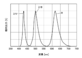
複数の励起光EB、及びEVが、細胞Cに結合された複数種の蛍光色素を励起することにより、細胞Cに結合された複数種の蛍光色素が異なる波長の蛍光を発光する。図17は、相対出力(%)を縦軸、波長(nm)を横軸とする、2つの励起光EB、及びEVにより励起された複数種の蛍光色素から発光される蛍光λ1B及びλ1Vと、第2光源50からの透過光Rのスペクトルのグラフである。図17に示されるように、蛍光λ1B及びλ1Vは、それぞれ、励起光EB及びEVより長波長側の波長帯域を有する。さらに、第2光源50からの透過光Rは、蛍光λ1B及びλ1Vとは異なる波長帯域を有することが理解できる。透過光R、蛍光1λB及びλ1Vが異なる波長帯域を有しているので、後述するように、撮像素子26において、2つの蛍光と1つの透過光を撮像することができる。
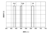
蛍光λ1B及びλ1V、透過光Rは、対物レンズ16、及び図16に示される分光特性を有するダイクロイックミラー20を透過し、第2マルチバンドパスフィルター22に到達する。ここで、図16に示されるとおり、ダイクロイックミラー20の分光特性よれば、蛍光λ1B、λ1V及び透過光Rの波長帯域の透過率が高い。したがって、蛍光λ1B、λ1V及び透過光Rは、ダイクロイックミラー20を透過する。図18は、透過率(%)を縦軸、波長(nm)を横軸とする、第2マルチバンドパスフィルター22の分光スペクトルを示すグラフである。図18に示されるように、第2マルチバンドパスフィルター22は、蛍光λ1B及びλ1Vと透過光Rの波長帯域より狭い波長帯域のみを透過させるF2B、F2V及びFRの分光スペクトルを備え、トリプルバンドパスフィルターとして構成することができる。
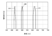
細胞Cから発光されダイクロイックミラー20を透過した蛍光λ1Bは、第2マルチバンドパスフィルター22を透過することにより、必要ない波長帯域の光がカットされる。細胞Cから発光されダイクロイックミラー20を透過した蛍光λ1Vは、第2マルチバンドパスフィルター22を透過することにより、必要ない波長帯域の光がカットされる。細胞C及びダイクロイックミラー20を透過した透過光Rは、第2マルチバンドパスフィルター22を透過することにより、必要ない波長帯域の光がカットされる。図19は、相対出力(%)を縦軸、波長(nm)を横軸とする、第2マルチバンドパスフィルター22を透過した蛍光及び透過光のスペクトルのグラフである。蛍光λ1Bは、第2マルチバンドパスフィルター22により不要な波長帯域がカットされ、蛍光λ1Bより波長帯域が狭い蛍光λ2Bが第2マルチバンドパスフィルター22から出力される。また、蛍光λ1Vは、第2マルチバンドパスフィルター22により不要な波長帯域がカットされ、蛍光λ1Vより波長帯域が狭い蛍光λ2Vが第2マルチバンドパスフィルター22から出力される。また、透過光Rは、第2マルチバンドパスフィルター22により不要な波長帯域がカットされ、透過光Rより波長帯域が狭い透過光λRが第2マルチバンドパスフィルター22から出力される。
撮像するステップでは、第2マルチバンドパスフィルター22を透過した蛍光λ2B及びλ2Vと、透過光λRは、1画素に複数の副画素を有する撮像素子26により撮像される。撮像素子26として、第1実施形態と同様の赤色フィルター、緑色フィルター及び青色フィルターとを有する単板式のカラー撮像素子を用いることができる。
撮像素子26により撮像された蛍光の強度と透過光の強度とが、例えば、制御部28に入力され、記憶される。制御部28により蛍光の強度と透過光の強度とが演算処理され、カラーの画像が取得される。
図20は、撮像素子26により取得された蛍光の強度に基づいて制御部28により取得された細胞Cから発光された蛍光と位相差像の画像の概念図である。図20には、有核赤血球70が表示されている。有核赤血球70では、幼弱な赤血球の蛍光は赤血球全体に均一に蛍光しないで局所的に蛍光する場合がある。この場合、蛍光では有核赤血球70の形状を把握することができない。このような場合に明視野像を撮影し重ねることで形状も知ることができる。明視野像はさらに位相差像を得ることでより形状の把握が明瞭になるので好ましい。
図20においては、有核赤血球70の内の核74が、例えば、蛍光色素により青色に発光し、有核赤血球70の内のHbF76(胎児ヘモグロビン)が、蛍光色素により緑色に発光している。有核赤血球70の外形形状79については、透過光を利用して位相差像が撮像されている。
本実施形態では、上述した、細胞Cから発光される異なる波長の蛍光と第2光源からの透過光を1回の撮影により、同時に撮像することができるので、細胞Cの撮像時間を短縮することができる。
10 画像撮像装置
12 第1光源
14 テーブル
16 対物レンズ
18 第1マルチバンドパスフィルター
20 ダイクロイックミラー
22 第2マルチバンドパスフィルター
24 フィルター群
26 撮像素子
28 制御部
40 容器
42 収納部
44 開口
46 側面
48 保持面
50 第2光源
60 白血球
62、72、82 表面
64、74 核
70 有核赤血球
76 HbF
78 外形形状
80 赤血球
260 画素
261、262、263、264 副画素
EB、EG、EV 励起光
R、λR 透過光λ1B、λ1G、λ1V、λ2B、λ2G、λ2V 蛍光
12 第1光源
14 テーブル
16 対物レンズ
18 第1マルチバンドパスフィルター
20 ダイクロイックミラー
22 第2マルチバンドパスフィルター
24 フィルター群
26 撮像素子
28 制御部
40 容器
42 収納部
44 開口
46 側面
48 保持面
50 第2光源
60 白血球
62、72、82 表面
64、74 核
70 有核赤血球
76 HbF
78 外形形状
80 赤血球
260 画素
261、262、263、264 副画素
EB、EG、EV 励起光
R、λR 透過光λ1B、λ1G、λ1V、λ2B、λ2G、λ2V 蛍光
Claims (15)
- 異なる波長の蛍光を発光する複数種の蛍光色素で染色された細胞を平坦な保持面で保持して収納する少なくとも一つの収納部と、
複数の波長の光を同時に発光する第1光源と、
前記第1光源から発光される前記複数の波長の光のうち前記複数種の蛍光色素を励起する複数の波長の励起光を選択的に透過させる第1マルチバンドパスフィルターと、前記第1マルチバンドパスフィルターを透過した前記複数の波長の励起光を前記細胞に向けて照射させ前記複数の波長の励起光により前記細胞から発光される前記異なる波長の蛍光を透過させるダイクロイックミラーと、前記ダイクロイックミラーを透過した前記異なる波長の蛍光を透過させる第2マルチバンドパスフィルターと、を含むフィルター群と、
前記複数の波長の励起光を集光し前記異なる波長の蛍光を拡大させる対物レンズと、
前記第2マルチバンドパスフィルターを透過した前記異なる波長の蛍光を撮像する1画素に複数の副画素を有する撮像素子と、
を有する画像撮像装置。 - 前記撮像素子がカラー撮像素子である請求項1に記載の画像撮像装置。
- 前記カラー撮像素子が、赤色フィルター、緑色フィルター、及び青色フィルターを有する単板式の撮像素子である請求項2に記載の画像撮像装置。
- 前記第1光源と、前記フィルター群と、前記撮像素子とが、前記収納部に対して前記保持面とは反対の側に配置される請求項1から3の何れか一項に記載の画像撮像装置。
- 前記第1マルチバンドパスフィルター、及び前記第2マルチバンドパスフィルターは、トリプルバンドパスフィルターで構成される請求項1から4の何れか一項に記載の画像撮像装置。
- 前記第1光源は、複数の光源により構成される請求項1に記載の画像撮像装置。
- 前記複数の光源の光量を、それぞれ独立に制御する制御部を有する請求項6に記載の画像撮像装置。
- 前記第1光源が、少なくとも緑色発光ダイオード、青色発光ダイオード、及び紫色発光ダイオードを含む光源である請求項6または7に記載の画像撮像装置。
- 前記収納部は、複数の収納部を有する容器の一つの収納部である請求項1から8の何れか一項に記載の画像撮像装置。
- 異なる波長の蛍光を発光する複数種の蛍光色素で染色された細胞を平坦な保持面で保持して収納する少なくとも一つの収納部と、
複数の波長の光を同時に発光する第1光源と、
前記収納部に対して前記第1光源とは反対の側に配置された、一つの波長の透過光を発光する第2光源と、
前記第1光源から発光される前記複数の波長の光のうち前記複数種の蛍光色素を励起する複数の波長の励起光を選択的に透過させる第1マルチバンドパスフィルターと、前記第1マルチバンドパスフィルターを透過した前記複数の波長の励起光を前記細胞に向けて照射させ前記複数の波長の励起光により前記細胞から発光される前記異なる波長の蛍光を透過させかつ前記第2光源から発光される前記一つの波長の透過光を透過させるダイクロイックミラーと、前記ダイクロイックミラーを透過した前記異なる波長の蛍光及び前記一つの波長の透過光を透過させる第2マルチバンドパスフィルターと、を含むフィルター群と、
前記複数の波長の励起光を集光し前記異なる波長の蛍光及び前記一つの波長の透過光を拡大させる対物レンズと、
前記第2マルチバンドパスフィルターを透過した前記異なる波長の蛍光と前記一つの波長の透過光を撮像する1画素に複数の副画素を有する撮像素子と、
を有する画像撮像装置。 - 前記撮像素子がカラー撮像素子である請求項10に記載の画像撮像装置。
- 前記カラー撮像素子が、赤色フィルター、緑色フィルター、及び青色フィルターを有する単板式の撮像素子である請求項11に記載の画像撮像装置。
- 前記第1光源が、緑色発光ダイオード、青色発光ダイオード、及び紫色発光ダイオードの群から選択される2つの発光ダイオードを含む光源である請求項10から12の何れか一項に記載の画像撮像装置。
- 異なる波長の蛍光を発光する複数種の蛍光色素で染色された細胞を平坦な表面に保持する保持面を有する少なくとも一つの収納部に収納するステップと、
第1光源から複数の波長の光を同時に発光するステップと、
前記第1光源から発光される前記複数の波長の光のうち前記複数種の蛍光色素を励起する複数の波長の励起光を第1マルチバンドパスフィルターに選択的に透過させ、ダイクロイックミラーにより前記第1マルチバンドパスフィルターを透過した前記複数の波長の励起光を前記細胞に向けて照射させ、前記複数の波長の励起光により前記細胞から発光される前記異なる波長の蛍光を前記ダイクロイックミラーを透過させ、前記ダイクロイックミラーを透過した前記異なる波長の蛍光を第2マルチバンドパスフィルターを透過させるステップと、
前記第2マルチバンドパスフィルターを透過した前記異なる波長の蛍光を1画素に複数の副画素を有する撮像素子により撮像するステップと、
を有する画像撮像方法。 - 異なる波長の蛍光を発光する複数種の蛍光色素で染色された細胞を平坦な表面に保持する保持面を有する少なくとも一つの収納部に収納するステップと、
第1光源から複数の波長の光を同時に発光し、前記収納部に対して前記第1光源と反対の側に配置される第2光源から一つの波長の透過光を発光するステップと、
前記第1光源から発光される前記複数の波長の光のうち前記複数種の蛍光色素を励起する複数の波長の励起光を第1マルチバンドパスフィルターに選択的に透過し、ダイクロイックミラーにより前記第1マルチバンドパスフィルターを透過した前記複数の波長の励起光を前記細胞に向けて照射させ、前記複数の波長の励起光により前記細胞から発光される前記異なる波長の蛍光と前記第2光源から発光される前記一つの波長の透過光とを前記ダイクロイックミラーを透過させ、前記ダイクロイックミラーを透過した前記異なる波長の蛍光と前記第2光源から発光される一つの波長の透過光とを第2マルチバンドパスフィルターを透過させるステップと、
前記第2マルチバンドパスフィルターを透過した前記異なる波長の蛍光と前記第2光源から一つの波長の透過光とを1画素に複数の副画素を有する撮像素子により撮像するステップと、
を有する画像撮像方法。
Priority Applications (2)
| Application Number | Priority Date | Filing Date | Title |
|---|---|---|---|
| JP2018508476A JPWO2017169083A1 (ja) | 2016-03-31 | 2017-02-02 | 画像撮像装置及び画像撮像方法 |
| US16/119,492 US20180372640A1 (en) | 2016-03-31 | 2018-08-31 | Imaging device and imaging method |
Applications Claiming Priority (2)
| Application Number | Priority Date | Filing Date | Title |
|---|---|---|---|
| JP2016-070143 | 2016-03-31 | ||
| JP2016070143 | 2016-03-31 |
Related Child Applications (1)
| Application Number | Title | Priority Date | Filing Date |
|---|---|---|---|
| US16/119,492 Continuation US20180372640A1 (en) | 2016-03-31 | 2018-08-31 | Imaging device and imaging method |
Publications (1)
| Publication Number | Publication Date |
|---|---|
| WO2017169083A1 true WO2017169083A1 (ja) | 2017-10-05 |
Family
ID=59963724
Family Applications (1)
| Application Number | Title | Priority Date | Filing Date |
|---|---|---|---|
| PCT/JP2017/003695 Ceased WO2017169083A1 (ja) | 2016-03-31 | 2017-02-02 | 画像撮像装置及び画像撮像方法 |
Country Status (3)
| Country | Link |
|---|---|
| US (1) | US20180372640A1 (ja) |
| JP (1) | JPWO2017169083A1 (ja) |
| WO (1) | WO2017169083A1 (ja) |
Cited By (4)
| Publication number | Priority date | Publication date | Assignee | Title |
|---|---|---|---|---|
| CN108836262A (zh) * | 2018-04-11 | 2018-11-20 | 秦少平 | 一种诱导荧光光谱图像融合影像光路 |
| EP3486705A1 (en) * | 2017-11-16 | 2019-05-22 | Koninklijke Philips N.V. | A multi-mode imager |
| US10837905B2 (en) | 2018-09-14 | 2020-11-17 | Kabushiki Kaisha Toshiba | Optical sensor |
| CN116583778A (zh) * | 2020-09-11 | 2023-08-11 | 苹果公司 | 用于发射显示器的具有滤色器的光学系统 |
Families Citing this family (6)
| Publication number | Priority date | Publication date | Assignee | Title |
|---|---|---|---|---|
| DE102017107348B4 (de) | 2017-04-05 | 2019-03-14 | Olympus Soft Imaging Solutions Gmbh | Verfahren zur zytometrischen Analyse von Zellproben |
| CN111984588A (zh) * | 2020-07-09 | 2020-11-24 | 新浪网技术(中国)有限公司 | 一种对象存储生命周期管理方法、装置及系统 |
| CN112345502A (zh) * | 2020-10-27 | 2021-02-09 | 天津市英贝特航天科技有限公司 | 一种用于消除荧光免疫分析仪中荧光噪声的检测仪 |
| CN116559135A (zh) * | 2023-05-18 | 2023-08-08 | 深圳艾米医疗科技有限公司 | 血细胞多模态成像装置、方法、系统及存储介质 |
| WO2025006249A1 (en) * | 2023-06-30 | 2025-01-02 | Affymetrix, Inc. | Fast microarray scanning using multiband filters |
| WO2025235781A1 (en) * | 2024-05-10 | 2025-11-13 | Element Biosciences, Inc. | Single color fluorescent optical systems |
Citations (10)
| Publication number | Priority date | Publication date | Assignee | Title |
|---|---|---|---|---|
| JP2004013128A (ja) * | 2002-06-11 | 2004-01-15 | Olympus Corp | 蛍光顕微鏡 |
| JP2005004221A (ja) * | 2003-06-13 | 2005-01-06 | Leica Microsystems Wetzlar Gmbh | 少なくとも1つのビームスプリッタと散乱光低減手段とを有する顕微鏡 |
| JP2005331887A (ja) * | 2004-05-21 | 2005-12-02 | Keyence Corp | 蛍光顕微鏡、蛍光顕微鏡装置を使用した表示方法、蛍光顕微鏡画像表示プログラム及びコンピュータで読み取り可能な記録媒体並びに記憶した機器 |
| JP2008015059A (ja) * | 2006-07-04 | 2008-01-24 | National Institute Of Advanced Industrial & Technology | 蛍光顕微鏡 |
| JP2009058304A (ja) * | 2007-08-30 | 2009-03-19 | Saitama Univ | 生体成分又はその機能の測定方法及び装置 |
| JP2010256623A (ja) * | 2009-04-24 | 2010-11-11 | Olympus Corp | 顕微鏡観察装置 |
| WO2011132587A1 (ja) * | 2010-04-23 | 2011-10-27 | 浜松ホトニクス株式会社 | 細胞観察装置および細胞観察方法 |
| WO2012149555A1 (en) * | 2011-04-28 | 2012-11-01 | Bio-Rad Laboratories, Inc. | Fluorescence scanning head with multiband detection |
| JP2013178290A (ja) * | 2010-06-30 | 2013-09-09 | Jvc Kenwood Corp | 光源装置及び照明装置 |
| WO2015093420A1 (ja) * | 2013-12-16 | 2015-06-25 | コニカミノルタ株式会社 | 細胞検出方法および細胞検出装置 |
Family Cites Families (4)
| Publication number | Priority date | Publication date | Assignee | Title |
|---|---|---|---|---|
| WO2002059584A2 (en) * | 2000-12-29 | 2002-08-01 | Chromagen, Inc. | Scanning spectrophotometer for high throughput fluorescence detection |
| US20060082768A1 (en) * | 2004-08-31 | 2006-04-20 | Wilson Denise M | Miniaturized fluorescence analysis system |
| EP2021773B1 (en) * | 2006-04-19 | 2015-03-25 | IT-IS International Ltd | Reaction monitoring method and apparatus |
| RU2009105892A (ru) * | 2006-07-20 | 2010-08-27 | Конинклейке Филипс Электроникс Н.В. (Nl) | Многоцветный биодатчик |
-
2017
- 2017-02-02 JP JP2018508476A patent/JPWO2017169083A1/ja not_active Abandoned
- 2017-02-02 WO PCT/JP2017/003695 patent/WO2017169083A1/ja not_active Ceased
-
2018
- 2018-08-31 US US16/119,492 patent/US20180372640A1/en not_active Abandoned
Patent Citations (10)
| Publication number | Priority date | Publication date | Assignee | Title |
|---|---|---|---|---|
| JP2004013128A (ja) * | 2002-06-11 | 2004-01-15 | Olympus Corp | 蛍光顕微鏡 |
| JP2005004221A (ja) * | 2003-06-13 | 2005-01-06 | Leica Microsystems Wetzlar Gmbh | 少なくとも1つのビームスプリッタと散乱光低減手段とを有する顕微鏡 |
| JP2005331887A (ja) * | 2004-05-21 | 2005-12-02 | Keyence Corp | 蛍光顕微鏡、蛍光顕微鏡装置を使用した表示方法、蛍光顕微鏡画像表示プログラム及びコンピュータで読み取り可能な記録媒体並びに記憶した機器 |
| JP2008015059A (ja) * | 2006-07-04 | 2008-01-24 | National Institute Of Advanced Industrial & Technology | 蛍光顕微鏡 |
| JP2009058304A (ja) * | 2007-08-30 | 2009-03-19 | Saitama Univ | 生体成分又はその機能の測定方法及び装置 |
| JP2010256623A (ja) * | 2009-04-24 | 2010-11-11 | Olympus Corp | 顕微鏡観察装置 |
| WO2011132587A1 (ja) * | 2010-04-23 | 2011-10-27 | 浜松ホトニクス株式会社 | 細胞観察装置および細胞観察方法 |
| JP2013178290A (ja) * | 2010-06-30 | 2013-09-09 | Jvc Kenwood Corp | 光源装置及び照明装置 |
| WO2012149555A1 (en) * | 2011-04-28 | 2012-11-01 | Bio-Rad Laboratories, Inc. | Fluorescence scanning head with multiband detection |
| WO2015093420A1 (ja) * | 2013-12-16 | 2015-06-25 | コニカミノルタ株式会社 | 細胞検出方法および細胞検出装置 |
Cited By (7)
| Publication number | Priority date | Publication date | Assignee | Title |
|---|---|---|---|---|
| EP3486705A1 (en) * | 2017-11-16 | 2019-05-22 | Koninklijke Philips N.V. | A multi-mode imager |
| WO2019096974A1 (en) * | 2017-11-16 | 2019-05-23 | Koninklijke Philips N.V. | A multi-mode imager |
| CN108836262A (zh) * | 2018-04-11 | 2018-11-20 | 秦少平 | 一种诱导荧光光谱图像融合影像光路 |
| CN108836262B (zh) * | 2018-04-11 | 2021-08-31 | 秦少平 | 一种诱导荧光光谱图像融合影像光路 |
| US10837905B2 (en) | 2018-09-14 | 2020-11-17 | Kabushiki Kaisha Toshiba | Optical sensor |
| CN116583778A (zh) * | 2020-09-11 | 2023-08-11 | 苹果公司 | 用于发射显示器的具有滤色器的光学系统 |
| US12591140B2 (en) | 2020-09-11 | 2026-03-31 | Apple Inc. | Optical systems with color filters for emissive displays |
Also Published As
| Publication number | Publication date |
|---|---|
| JPWO2017169083A1 (ja) | 2019-02-07 |
| US20180372640A1 (en) | 2018-12-27 |
Similar Documents
| Publication | Publication Date | Title |
|---|---|---|
| WO2017169083A1 (ja) | 画像撮像装置及び画像撮像方法 | |
| KR101260051B1 (ko) | 살아있는 세포에 대한 명시야 이미징 및 형광 이미징의 동시 수행이 가능한 세포 이미징 장치 및 방법 | |
| KR101414248B1 (ko) | 형광 이미징 장치 | |
| US10151907B2 (en) | Full-color three-dimennsional optical sectioning microscopic imaging system and method based on structured illumination | |
| JP6237626B2 (ja) | 光学装置及び撮像装置 | |
| US10429630B2 (en) | Microscope for transmitted-light and fluorescence microscopy | |
| KR102114628B1 (ko) | 스펙트럼 현미경 | |
| US8809809B1 (en) | Apparatus and method for focusing in fluorescence microscope | |
| US9841378B2 (en) | Series absorbance glass and interference filters | |
| US8907312B2 (en) | Cytometry system with solid numerical-aperture-increasing lens | |
| WO2010108042A2 (en) | Non-coherent light microscopy | |
| KR20120024436A (ko) | 멀티 형광영상 관측용 형광현미경, 이를 이용한 형광영상의 관찰방법 및 멀티 형광영상 관측 시스템 | |
| CN103513411A (zh) | 荧光显微镜中聚焦的装置和方法 | |
| JP6075963B2 (ja) | 蛍光観察方法及び蛍光観察装置 | |
| CN109791275B (zh) | 观察装置 | |
| US20080151367A1 (en) | Microscope image processing device, microscope image processing program product, microscope image processing program transmission medium, and microscope image processing method | |
| US11668918B2 (en) | System and method for fluorescence microscopy with detection of light emission from multiple fluorochromes | |
| JP2012215609A (ja) | 培養細胞観察用顕微鏡装置 | |
| CN102047099A (zh) | 光学照射设备和方法 | |
| US20170031148A1 (en) | LED Microscope | |
| Eger | Engineering Approaches to Calibration Standard and Optomechanical Design for Point-of-Care Fluorescence Instrumentation | |
| JP2008076530A (ja) | 顕微鏡 | |
| JP2012127924A (ja) | 複数の対象物の検出装置及び検出方法 | |
| KR20250008251A (ko) | 미세 영상 장치 | |
| JP2010054690A (ja) | 共焦点顕微鏡 |
Legal Events
| Date | Code | Title | Description |
|---|---|---|---|
| WWE | Wipo information: entry into national phase |
Ref document number: 2018508476 Country of ref document: JP |
|
| NENP | Non-entry into the national phase |
Ref country code: DE |
|
| 121 | Ep: the epo has been informed by wipo that ep was designated in this application |
Ref document number: 17773632 Country of ref document: EP Kind code of ref document: A1 |
|
| 122 | Ep: pct application non-entry in european phase |
Ref document number: 17773632 Country of ref document: EP Kind code of ref document: A1 |