WO2017169232A1 - Image reconstruction method for interior ct - Google Patents
Image reconstruction method for interior ct Download PDFInfo
- Publication number
- WO2017169232A1 WO2017169232A1 PCT/JP2017/005515 JP2017005515W WO2017169232A1 WO 2017169232 A1 WO2017169232 A1 WO 2017169232A1 JP 2017005515 W JP2017005515 W JP 2017005515W WO 2017169232 A1 WO2017169232 A1 WO 2017169232A1
- Authority
- WO
- WIPO (PCT)
- Prior art keywords
- image
- interior
- image reconstruction
- roi
- piecewise
- Prior art date
- Legal status (The legal status is an assumption and is not a legal conclusion. Google has not performed a legal analysis and makes no representation as to the accuracy of the status listed.)
- Ceased
Links
Images


Classifications
-
- A—HUMAN NECESSITIES
- A61—MEDICAL OR VETERINARY SCIENCE; HYGIENE
- A61B—DIAGNOSIS; SURGERY; IDENTIFICATION
- A61B6/00—Apparatus or devices for radiation diagnosis; Apparatus or devices for radiation diagnosis combined with radiation therapy equipment
- A61B6/02—Arrangements for diagnosis sequentially in different planes; Stereoscopic radiation diagnosis
- A61B6/03—Computed tomography [CT]
Definitions
- the present invention relates to an image reconstruction method for measuring a line integral value of a physical quantity distribution inside an object and generating an image of the physical quantity distribution by data processing, and more particularly to an image reconstruction method for interior CT.
- ROI Region of interest
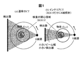
- an X-ray beam that completely covers the cross-section including the ROI is irradiated. Instead, the projection data on all straight lines passing through the cross section of the object are measured (see FIG. 1A).
- the interior CT is a method of CT imaging in which only the ROI is irradiated with X-rays and only the projection data on (all) straight lines passing through the ROI are measured to generate only the ROI image (FIG. 1). (See (b)).
- This interior CT has various advantages over conventional CT that measures unnecessary projection data wastefully. For example, (1) a significant reduction in exposure outside the ROI (sample damage), (2) a reduction in detector size and X-ray beam width, and (3) a large object that does not fit in the field of view can be taken. (4) High-resolution CT imaging can be performed in which only a small field of view of an object is irradiated with X-rays for enlarged imaging.
- Non-Patent Document 1 Natterer mathematically proves that the image reconstruction of the interior CT does not determine the solution to be “unique” (here, unique means that the image reconstruction solution is derived from the projection data). Because this non-uniqueness is known, it has been studied many approximate image reconstruction methods.
- Non-Patent Document 7 a lack of measurement data called compressed sensing is disclosed. Based on the method of signal restoration with high accuracy from the above, it is proved that if the image f (x, y) is piecewise uniform throughout the ROI S, the image reconstruction solution of the interior CT is uniquely determined did. However, the piecewise uniform means that the image is composed of a finite number of regions having a completely constant value like a numerical phantom (see FIG. 2B). This result is already known as a US patent (Patent Document 2).
- Non-Patent Document 5 In order to use the exact solution known from Non-Patent Document 5 and Non-Patent Document 6 described above, a priori knowledge about an object (an image of an image in an arbitrary small region B inside ROI S before imaging). Value) must be known. However, it is rare that the value of the image is known before shooting. In the exact solution of Non-Patent Document 7 described above, it is necessary to assume that the image is piecewise uniform over the entire ROI S, but this is not possible for a general CT image having a smooth density change. In this method, there is a risk that a smooth density change may be lost (an example is shown in FIG. 9 later).
- the present invention has been developed from a strict interior CT image reconstruction method using the above-mentioned a priori knowledge, and in the points described below, a more practical interior CT image reconstruction method.
- the purpose is to provide.
- an image reconstruction method for interior CT in which projection data is acquired by a quantum beam passing through an ROI inside an imaging target, and the projection obtained above is obtained.
- approximate reconstruction is performed by CT image reconstruction using data, and an image numerical value representing a physical quantity in the ROI based on the CT image reconstructed above is at least piecewise uniform or A region that is represented by a piecewise polynomial is specified, and the physical quantity is at least piecewise uniform or a piecewise polynomial expression that indicates the position of the specified region and the physical quantity is piecewise uniform inside or
- An interior CT image reconstruction method is provided that performs second-stage reconstruction with higher accuracy than the first-stage reconstruction using the property expressed in a piecewise polynomial form.
- the numerical value of the projection data representing the physical quantity may include absorption of the quantum beam by the imaging target, or the imaging CT
- the phase shift of the quantum beam may be included, the diffraction of the quantum beam by the imaging target may be included, or the scattering of the quantum beam by the imaging target may be included.
- the numerical value of the projection data including the phase shift, the phase shift of the quantum beam, diffraction, or diffraction is added to the detector by adding an optical element or changing its position. It is also possible to reconstruct an image using a numerical value of the projection data extracted from a set of acquired intensity data of the plurality of quantum beams and including the phase shift, diffraction, or diffraction of the extracted quantum beams. is there.
- the region in which the physical quantity specified in at least the ROI is piecewise uniform or piecewise represented by a polynomial is piecewise uniform or piecewise represented by a polynomial.
- the CT image value reconstructed by the approximate reconstruction in the first stage may be a region in which the values are piecewise uniform or piecewise represented by a polynomial, or the CT reconstructed in the first step.
- the at least piecewise uniform or piecewise polynomial region identified within the ROI of an image may be selectable within the ROI.
- the at least piecewise uniform or piecewise polynomial area specified in the ROI is an approximation of the first step. May be set manually by a human using a CT image obtained by simple reconstruction, or set by image processing using a CT image obtained by approximate reconstruction in the first stage. May be. Alternatively, it may be set in advance in the ROI by at least one of specifying from the previously acquired CT image of the imaging target, a model representing the structure of the imaging target, and specification from a priori information. Note that the at least piecewise uniform or piecewise polynomial area specified in the ROI using the CT image obtained by the approximate reconstruction in the first stage is the boundary of the ROI. A part may be formed.
- the first-stage approximate reconstruction includes conventional CT images including a filtered back projection (FBP) method, a successive approximation method, and a statistical reconstruction method.
- the second stage reconstruction may be performed by a differential backprojection Hilbert transform method, a constrained successive approximation method, and a constrained statistical reconstruction method. You may perform by at least 1 of the image reconstruction method of CT containing.
- FIG. 11 is a diagram showing an actual reconstruction example when a priori knowledge of [Result 1] to [Result 3] is used. It is a flowchart figure which shows the detail of the two step image reconstruction method of this invention. It is a figure which shows an example of the incomplete image and exact image in the two-step image reconstruction method of this invention.
- the key elements of the present invention are (1) exact reconstruction theory using much less a priori knowledge, and (2) a priori knowledge identification type image reconstruction that identifies a priori knowledge from projection data. (3) An a priori knowledge non-identification type image reconstruction method that fixes a priori knowledge without identifying it. A newly proposed image reconstruction method for this purpose will be described in detail below.
- the interior CT is compared with normal CT (see FIG. 1 (a)) that irradiates the entire object that is the subject with X-rays from an X-ray source,
- a part of a large object region of interest (ROI)
- ROI region of interest
- Example 1 is an “a priori knowledge identification type image reconstruction method” in which a priori knowledge necessary for strict image reconstruction is automatically identified from projection data and used for strict image reconstruction. This will be described below with reference to FIGS. 6 and 7A and 7B.
- FIG. 6 shows a processing flow of the image reconstruction method which is a method proposed in the present invention.
- This proposed method is a so-called two-stage image reconstruction method including a first step and a second step.
- the first first step (S61) an incomplete image including artifacts is generated using a conventional FBP method, a successive approximation image reconstruction method, a statistical image reconstruction method, or the like without a priori knowledge.
- This incomplete image includes artifacts, but since the artifacts generated in the interior CT are low frequency components, information on the boundaries of structures such as organs and tissues is accurately reflected in most cases.
- a priori information area B which is an arbitrary small area in ROI S that can be used as experimental knowledge is identified (S62). Then, in the second step, the prior information area B obtained in the first step is used for a priori knowledge, and as shown in FIG. Image reconstruction is performed with higher accuracy than the one-stage reconstruction (S63). Note that which one of [Result 1] to [Result 4] is used is determined depending on what a priori information area B can be extracted in the first step. For example, [Result 1] is definitely a constant B, and [Result 3] is definitely a piecewise uniform B. Although it is not a constant, B is close to a change in the density of a polynomial. [Result 2] is selected, and [Result 4] is selected and used if B is close to the density change of the piecewise polynomial.
- ⁇ Result 3 (Categorical uniform a priori knowledge)> As shown in FIG. 2 (a), it is known that an arbitrary small a priori information area B exists inside ROI S, and f (x, y) is known piecewise constant in B. If so, the image reconstruction solution for the interior CT is uniquely determined.
- the piecewise uniform means that, as shown in FIG. 4, B is composed of a finite number (L) of regions D 1 , D 2 ,..., D L and each region has a constant value C 1 , C 2. ,..., C L.
- the number of regions L and the values of constant values C 1 , C 2 ,..., C L may be unknown in advance, in other words, [Result 3] is obtained by reducing the a priori knowledge of [Result 1]. It has become.
- ⁇ Result 4 (a piecewise polynomial a priori knowledge)>
- an arbitrary small a priori information region B exists inside ROI S
- f (x, y) is an M-order piecewise polynomial in B.
- the image reconstruction solution for the interior CT is uniquely determined.
- the piecewise polynomial, region D 1 of the B is a finite number (L number) as shown in FIG. 4, D 2, ..., density change in the image of the l-th region consists D L f l ( x, y) has the following form:
- Patent Documents 5 and 6, Patent Document 1 a priori knowledge about an object necessary for performing strict image reconstruction is theoretically considered and described in the above prior arts. It can be seen that strict image reconstruction is possible with much less a priori knowledge than a priori knowledge.
- Non-Patent Documents 5 and 6 the same a priori knowledge of an arbitrary small region B in ROI S as [Result 1] to [Result 4] is used, but the image f (x, y) Whereas the value itself is required, in the present invention, in [Result 1] to [Result 4], the value of f (x, y) is much smaller, such as (piecewise) uniform or (piecewise) polynomial. It differs greatly only in a priori knowledge.
- Non-Patent Document 7 a priori knowledge of piecewise uniform type is used, but an unreasonable assumption is necessary that piecewise uniform throughout ROI S, not an arbitrary small region B in ROI S. It is different in point.
- FIGS. 5A to 5C show actual reconfiguration examples when the a priori knowledge of [Result 1] to [Result 3] is used. In any case, it can be seen that significant artifact reduction can be achieved with a little a priori knowledge.
- Example 2 is an “a priori knowledge automatic estimation type image reconstruction method” for identifying a priori knowledge from projection data.
- a priori knowledge necessary for strict image reconstruction of the interior CT can be much lessened.
- a priori knowledge about an object of interest is known before imaging, for example, a CT image previously captured of the same patient or an image captured with another modality. Limited to very few special cases, such as
- identifying the a priori information area B that is an arbitrary small area in ROI S that can be used as a priori knowledge in step S62 in the process flow shown in FIG. It identifies automatically without going through. It will be apparent to those skilled in the art that the automatic identification of the a priori information area can be easily realized by using, for example, an image analysis (processing) technique.
- the success or failure of the a priori knowledge automatic estimation type image reconstruction method described in the second embodiment depends on whether or not the a priori knowledge (a priori information area B) can be identified successfully in the first step.
- the step of identifying the a priori information area is somewhat complicated, there may be a desire not to perform the identifying step.
- the edge portion around ROI S A method of applying a strict image reconstruction method based on [Result 3] or [Result 4] is proposed.
- the assumption that the edge part around ROI S is piecewise uniform or piecewise polynomial is not strictly correct, so the method is only an approximate image reconstruction method, but many CT imaging In this situation, [Knowledge 3] holds, so that image reconstruction can be performed much better compared to other approximate image reconstruction methods that do not use a priori knowledge (studied before the discovery of the exact solution). Be expected.
- FIGS. 9A to 9F show specific examples of the a priori knowledge identification type image reconstruction method (Example 1) and the a priori knowledge non-identification type image reconstruction method (Example 3).
- An example of a simple simulation experiment is shown by comparison with the prior art. The chest CT image was used for the experiment, and the image was reconstructed with the heart located at the center as ROI S (see FIG. 9A).
- the user looks at the reconstructed image by the FBP method in the first step, designates the a priori information area B in ROI S, and performs the strict image reconstruction in the second step (note that The a priori knowledge was piecewise uniform with B corresponding to [Result 3]).
- the result is shown in FIG.
- image reconstruction was performed with the a priori information area B fixed to the periphery of the ROI (S (the frame type in FIG. 8C). 3] is piecewise uniform with B corresponding to). The result is shown in FIG.
- FIG. 9B shows the result of the local FBP method in which the FBP method is applied by extrapolating the missing portion of the projection data with a smooth function.
- FIG. 9D shows the results obtained by the compression sensing method (Non-Patent Document 7) that applies a total variation (TV: Total Variation), which is a constraint of the above.
- the local FBP method has a strong cupping effect and image degradation is significant, and the compression sensing method has lost considerable details and smooth density changes due to the influence of TV.
- the image can be reconstructed quite well by reducing artifacts.
- an image reconstruction method for generating an image from projection data based on the uniqueness of the solutions of [Result 1] to [Result 4] described above will be described.
- any image reconstruction method that uses a priori knowledge as a constraint condition can generate an image precisely.
- image reconstruction methods can be constructed by the following procedure. First, vectors obtained by discretizing the image f (x, y) and the projection data p (r, ⁇ ) are represented by x and b, respectively, and a projection calculation matrix that associates the projection data with the image is represented by A.
- the image x includes not only the pixels in the ROIS but also all the pixels belonging to the object existence region in the cross section (caution is required), and the projection data vector b is created by arranging all the measured values in a line. Further, an evaluation function for evaluating whether a priori knowledge is satisfied in the a priori information area B is represented by F (x). At this time, the image reconstruction can be formulated as one of the following three optimization problems.
- x ⁇ C represents a constraint condition that can be known in advance with respect to an image, and the following is often used.
- A (Support Constraint) The image x becomes zero outside the support region ⁇ OBJ that is known in advance.
- B Non-negative condition
- the component of the image x does not take a negative value.
- F (x) is a function that does not have a local optimal solution called local function (local minimum)
- local function local minimum
- iterative or non-iterative solutions to solve the above problem in the mathematical optimization and image reconstruction fields. All of these techniques are available.
- a statistical image reconstruction method with a constraint condition or a successive approximation method with a constraint condition can be used.
- an image reconstruction method can be constructed based on a later-described framework called differential back projection (DBP).
- DBP differential back projection
- the idea for designing F (x) is as follows. First, unlike the methods of Non-Patent Document 7 and Non-Patent Document 8 in which a constraint condition based on a priori knowledge is applied to the entire ROI S, the image reconstruction method of the present invention is an a priori that is an arbitrary small region in S. Constraint conditions are imposed only on information area B. In the case of [Result 1], the norm of the first derivative of f (x, y) in B is minimized because the first derivative of f (x, y) is zero in B. Or the variation (dispersion) in density change in B may be minimized.
- Table 1 shows typical F (x) examples, though not all can be given because there are various options.
- the parameter p is the norm order, and its value may be 0 ⁇ p ⁇ 2 in [Result 1] and [Result 2], but is uniform or M in [Result 3] and [Result 4]. It is necessary to use 0 ⁇ p ⁇ 1 in order to avoid that the influence of the boundary of a finite number (L) of partial areas having density changes of the following polynomial is evaluated too large.
- the F (x) shown in Table 1 with multiple candidates was tested by numerical experiments, but all of them worked well and there was no significant difference.
- ROI S is first decomposed into a set of straight lines L (u); u ⁇ U (u is a parameter representing a straight line) called a Hilbert line. Then, the DBP method is used to perform image reconstruction by reducing the image reconstruction to an inverse transformation of an integral transformation called a Hilbert transform for each Hilbert straight line L (u). However, the set of Hilbert straight lines L (u); u ⁇ U is selected so as to satisfy the following two conditions.
- Each point (x, y) of S belongs to at least one L (u).
- All L (u) intersect with the a priori information area B in which the value of f (x, y) is known in advance.
- 10 (b) and 10 (c) show how to take a typical Hilbert straight line L (u); u ⁇ U. After decomposing S into Hilbert straight lines in this way, image reconstruction is performed for each L (u) by the following processing procedure.
- ⁇ (u) represents the angle that L (u) makes with the x-axis. Note that in the region outside L (u) ⁇ S, angle truncation of projection data occurs due to truncation, and DBP cannot be calculated.
- pv represents the main value of Cauchy of integration
- points a, b, c, d, e, and f are defined as shown in FIG. That is, the image reconstruction on L (u) is reduced to the inverse transform of the Hilbert transform of equation (10).
- the observation interval [b, e] of the Hilbert transform measurement data g (t) is completely included in the support (non-zero) interval [a, f] of the image f (t), and g (t) is The range of [a, b] ⁇ [e, f] on both the left and right sides is truncated.
- the section [a, f] corresponding to the object existence area (support) is set to ⁇ OBJ
- the section [b, e] corresponding to ROI S is set to ⁇ ROI
- the section [c, d corresponding to the a priori information area B is set. ] Is represented as ⁇ PRI (see FIG. 10A).
- f (t) is uniquely determined at every point on the Hilbert straight line L (u). This holds for all Hilbert lines L (u), and the set of Hilbert lines L (u); u ⁇ U is taken to cover ROI S, so f (x, y) is unique in ROI S Determined.
- f (x, y) is uniquely determined up to the point covered by the Hilbert straight line outside ROI S, but the projection data p (r , ⁇ ) has an angular defect (not measured by 180 °), so that the value of f (x, y) is substantially stable and the image can be correctly reconstructed only at a point inside ROIS.
- [Result 1] to [Result 3] are positioned as special cases in which the polynomial degree M of the a priori knowledge used in [Result 4] and the piecewise uniform region number L are as follows.
- g (M + 1) (t) and f (M + 1) (t) are the M + 1 derivatives of g (t) and f (t), respectively, and g (M + 1) (t ) (T ⁇ ROI ) can be calculated from g (t) (t ⁇ ROI ).
- f (t) (t ⁇ PRI ) is an M-order piecewise polynomial, so f (M + 1) (t) (t ⁇ PRI ) is Dirac. It is expressed in the following form using the ⁇ function.
- the M + 1 derivative g (M + 1) (t) (t ⁇ ROI ) can be calculated from the measured projection data g (t) (t ⁇ ROI ), and g (M + 1) From the a priori knowledge that (t) (t ⁇ ROI ) and f (t) (t ⁇ PRI ) are M-order piecewise polynomials, f (M + 1) (t) ( ⁇ ⁇ t ⁇ ⁇ ) is uniquely determined. If f (M + 1) (t) ( ⁇ ⁇ t ⁇ ) is uniquely determined, f (t) (t ⁇ OBJ ) is uniquely determined by the following equation.
- the present invention can be applied to any CT imaging apparatus based on the principle of measuring the line integral value of a physical quantity distribution inside an object and generating an image of the physical quantity distribution by data processing. is there.
- CT generally refers to absorption X-ray CT that generates an image of an X-ray absorption coefficient distribution in many cases, and therefore, the image reconstruction method according to the embodiment of the present invention will be described below.
- an outline of an X-ray CT apparatus that obtains a cross-sectional image of the inside of a subject using X-rays will be described with reference to the drawings.
- FIG. 11 attached will illustrate an embodiment of the present invention in which the above-described image reconstruction method is used to measure a line integral value of a physical quantity distribution inside an object and generate an image of the physical quantity distribution by data processing.
- the whole external appearance structure of a general X-ray CT apparatus is shown. That is, the X-ray CT apparatus accommodates components such as an X-ray irradiation unit, which will be described below, and a gantry unit 1 having a substantially cylindrical hollow portion in which a subject is positioned at the center thereof, A base unit 2 having a top plate (cradle) 4 on which an object is placed, a computer (not shown here) that is a data processing device, and an image obtained are displayed.
- a console unit 3 including a display device 5 and a keyboard 6 for performing necessary input is provided.
- components constituting the X-ray CT apparatus are provided in the housing of the gantry unit 1 and the console unit 3 as shown in FIG.
- an X-ray generator 10 that irradiates a sample with X-rays in a fan shape, and a circle that detects X-rays irradiated from the apparatus and transmitted through the subject.
- the arc-shaped X-ray detection apparatus 20 is attached on, for example, a ring-shaped frame.
- a space between the X-ray generator 10 and the X-ray detector 20 is provided with a top board 30 (corresponding to reference numeral 4 in FIG. 11) on which the subject is placed (set).
- a member to which the X-ray generation device 10 and the X-ray detection device 20 are attached is a rotation drive mechanism such as a motor provided inside the gantry unit 1 via the rotation drive unit 50. Rotate in a predetermined direction at a predetermined rotation speed (see arrows in the figure).
- the top plate 30 for placing the subject is disposed so as to oppose a cylindrical space at a substantially central portion of the rotation surfaces of the X-ray generation device 10 and the X-ray detection device 20 and moves the sample placement table.
- the unit 60 It is moved by the unit 60. Furthermore, the X-ray generator 10 and the X-ray detector 20 are controlled by the rotation control of the motor, an X-ray high voltage unit 40 for generating and supplying a high voltage to the X-ray generator 10. A rotation driving unit 50 for rotating the member to which the motor is attached is provided.
- the detection signal from the X-ray detection apparatus 20 described above is input to the data collection unit 70 and collected as image data, and further reproduced by the image reproduction unit 75 as a cross-sectional image or a three-dimensional image inside the sample. Is done.
- Reference numeral 76 in the drawing denotes a storage device (image memory) used when the image reproducing unit 75 reproduces a cross-sectional image or a three-dimensional image inside the sample.
- the cross-sectional image or the three-dimensional image inside the sample reproduced by the image reproducing unit 75 is displayed on an image display unit 80 (corresponding to reference numeral 5 in FIG. 11) configured by a liquid crystal display device or the like, for example. .
- the image display unit 80 can perform input necessary for operating the apparatus.
- the apparatus may include a keyboard (corresponding to reference numeral 6 in FIG. 11), a numeric keypad, a mouse, and the like instead of the touch panel.
- reference numeral 90 in the drawing indicates a control unit (corresponding to reference numeral 3 in FIG. 11) for controlling the operation of each unit constituting the above-described X-ray CT apparatus. More specifically, for example, it is constituted by a central processing unit (CPU), a storage device (memory) such as a RAM or a ROM, and an external storage device such as an HDD, and the like. Necessary control is executed based on software and firmware for controlling the operation of each unit stored in the.
- CPU central processing unit
- storage device such as a RAM or a ROM
- HDD high-ray CT apparatus
- the image reconstruction method for interior CT according to the present invention described above is stored in a storage device (memory) such as RAM or ROM as software in the image reproduction unit 75 constituting the X-ray CT apparatus, It is executed by a central processing unit (CPU).
- a storage device such as RAM or ROM as software in the image reproduction unit 75 constituting the X-ray CT apparatus, It is executed by a central processing unit (CPU).
- CPU central processing unit
- phase X-ray CT for generating an image of a phase shift distribution from line integral data of a phase shift distribution when X-rays are irradiated
- SPECT Single Photon Emission CT
- CT single Photon Emission CT
- CT electron beam CT
- projection data using ultrasonic waves, microwaves, sound waves, seismic waves, etc.
- object or “image” refers to a spatial distribution of physical quantities to be imaged
- projection data refers to measurement data representing a line integral value on the straight line.
- the numerical value of the projection data including phase shift, quantum beam phase shift, diffraction, or diffraction is extracted from a set of intensity data of a plurality of quantum beams acquired by a detector by adding an optical element or changing its position, It is also possible to reconstruct an image using numerical values of the projection data including phase shift, diffraction, or diffraction of the extracted quantum beam.
- the present invention provides an image reconstruction method, particularly an interior CT image reconstruction method, that measures a line integral value of a physical quantity distribution inside an object and generates an image of the physical quantity distribution by data processing.
Landscapes
- Health & Medical Sciences (AREA)
- Life Sciences & Earth Sciences (AREA)
- Medical Informatics (AREA)
- Engineering & Computer Science (AREA)
- Radiology & Medical Imaging (AREA)
- Biomedical Technology (AREA)
- Biophysics (AREA)
- Nuclear Medicine, Radiotherapy & Molecular Imaging (AREA)
- Optics & Photonics (AREA)
- Pathology (AREA)
- Physics & Mathematics (AREA)
- High Energy & Nuclear Physics (AREA)
- Heart & Thoracic Surgery (AREA)
- Molecular Biology (AREA)
- Surgery (AREA)
- Animal Behavior & Ethology (AREA)
- General Health & Medical Sciences (AREA)
- Public Health (AREA)
- Veterinary Medicine (AREA)
- Apparatus For Radiation Diagnosis (AREA)
Abstract
Description
本発明は、物体内部における物理量分布の線積分値を測定してデータ処理により物理量分布を画像生成する画像再構成方法に関し、特に、インテリアCTの画像再構成方法に関する。 The present invention relates to an image reconstruction method for measuring a line integral value of a physical quantity distribution inside an object and generating an image of the physical quantity distribution by data processing, and more particularly to an image reconstruction method for interior CT.
まず、インテリアCT(コンピュータトモグラフィー)と呼ばれるCT撮影の方法について説明する。一般的に、CTイメージングの多くの状況においては、対象物(試料)内の小さな関心領域(ROI:Region of Interest)だけの画像が欲しい場合が生じる。例えば、医療用CTを用いた心臓病や乳がんの診断では、心臓や乳房を含む小さなROIの画像だけがあれば十分である。現在のCT装置の構成方式やデータ収集法は、このようなROIだけの画像で十分な場合であっても、ROIを含む断面を完全に覆うX線ビームを照射して、即ち、ROIのみではなく、対象物断面を通過する全ての直線上の投影データを測定するものになっている(図1(a)を参照)。これは、CT装置の画像再構成に用いられる計算手順であるフィルタ補正逆投影(FBP:Filtered Backprojection)法において、ROI画像を生成するのにROIを通過しない直線上の投影データも必要になるためである。しかし、直感的には、ROIを通過しない直線上の投影データはROIの情報を全く含んでいないため、不必要なことが予想される。そこで、ROIだけにX線を照射して、ROIを通過する(全ての)直線上の投影データのみを測定してROIの画像のみを生成するCT撮影の方法が、インテリアCTである(図1(b)を参照)。 First, a CT method called interior CT (computer tomography) will be described. In general, in many situations of CT imaging, an image of only a small region of interest (ROI: Region of interest) in an object (sample) may be desired. For example, in the diagnosis of heart disease and breast cancer using medical CT, it is sufficient to have only a small ROI image including the heart and breast. Even if the configuration method and the data acquisition method of the current CT apparatus are sufficient in the case where such an ROI-only image is sufficient, an X-ray beam that completely covers the cross-section including the ROI is irradiated. Instead, the projection data on all straight lines passing through the cross section of the object are measured (see FIG. 1A). This is because, in the filtered back projection (FBP) method, which is a calculation procedure used for image reconstruction of the CT apparatus, projection data on a straight line that does not pass through the ROI is also required to generate the ROI image. It is. However, intuitively, since projection data on a straight line that does not pass through the ROI does not include any ROI information, it is expected to be unnecessary. Therefore, the interior CT is a method of CT imaging in which only the ROI is irradiated with X-rays and only the projection data on (all) straight lines passing through the ROI are measured to generate only the ROI image (FIG. 1). (See (b)).
このインテリアCTには、不必要な投影データを無駄に測定する従来のCTと比較して、様々な長所がある。例えば、(1)ROI外部の被曝量(試料損傷)の大幅な低減、(2)検出器サイズやX線ビーム幅の削減、(3)視野に収まらない大きい物体の撮影が可能になること、(4)物体の小視野だけにX線を照射して拡大撮影する高分解能CTイメージングが可能になること等が挙げられる。 This interior CT has various advantages over conventional CT that measures unnecessary projection data wastefully. For example, (1) a significant reduction in exposure outside the ROI (sample damage), (2) a reduction in detector size and X-ray beam width, and (3) a large object that does not fit in the field of view can be taken. (4) High-resolution CT imaging can be performed in which only a small field of view of an object is irradiated with X-rays for enlarged imaging.
一方、インテリアCTでは、ROIを通過しない直線上の投影データは測定されないため、一部が欠損した不完全投影データから画像再構成を行う手法が必要となる。より正確に、上記したインテリアCTにおける画像再構成問題の定義を述べると、以下のようになる。即ち、対象物f(x,y)と画像化の対象となるROI Sを考える(図2(a)を参照)。そして、直線がROI Sを通過する投影データp(r,θ)(rは動径、θは角度)のみが測定可能であるとする。ただし、簡単のため、平行ビームによる投影データ収集を想定している。この場合、直線がROI Sを通過しないp(r,θ)は測定されないため、各角度θの投影データは、左右がトランケーションされて欠損することになる。このようなトランケーションされた投影データからROI Sにおいて画像f(x,y)を正しく再構成する問題が、所謂、インテリアCTの画像再構成である。 On the other hand, in the interior CT, projection data on a straight line that does not pass through the ROI is not measured. Therefore, a method of performing image reconstruction from incomplete projection data partially missing is necessary. More precisely, the definition of the above-described image reconstruction problem in the interior CT will be described as follows. That is, consider the object f (x, y) and the ROI S to be imaged (see FIG. 2A). Then, it is assumed that only the projection data p (r, θ) (r is the moving radius and θ is the angle) in which the straight line passes through ROI S can be measured. However, for the sake of simplicity, it is assumed that projection data is collected by a parallel beam. In this case, since p (r, θ) where the straight line does not pass through ROI S is not measured, the projection data at each angle θ is truncated and lost. The problem of correctly reconstructing the image f (x, y) in ROI S from such truncated projection data is the so-called interior CT image reconstruction.
なお、この問題は長年多くの研究が行われてきており、以下に概略する。まず、非特許文献1では、Nattererは、インテリアCTの画像再構成は解が「一意」に定まらないことを数学的に証明し(ここで、一意とは、画像再構成の解が投影データから唯一に決まり数学的に正しい画像再構成が可能なことを指す)、この非一意性が知られていたため、多くの近似的な画像再構成法が研究されてきた。 This problem has been studied for many years and is outlined below. First, in Non-Patent Document 1, Natterer mathematically proves that the image reconstruction of the interior CT does not determine the solution to be “unique” (here, unique means that the image reconstruction solution is derived from the projection data). Because this non-uniqueness is known, it has been studied many approximate image reconstruction methods.
例えば、その代表的な手法として、(1)各方向投影データ左右の欠損部分を滑らかな関数で外挿してから画像再構成する手法、(2)不完全な投影データのまま逐次近似法により画像再構成を行う手法などが研究されたが、近似誤差によるアーティファクトが発生して実用に至らなかった(非特許文献2、3、4)。このインテリアCTにおいて発生する典型的なアーティファクトの例を示すと、画像低周波成分に歪みが発生するシェーディングアーティファクト(図3(a)を参照)やROI周辺部で値が増大するカッピング効果(図3(b)を参照)が発生し、画像の値が安定に定まらないことが知られている。
For example, as a typical technique, (1) a method of reconstructing an image after extrapolating the left and right missing portions of each direction projection data with a smooth function, and (2) an image by successive approximation with incomplete projection data. Although methods for performing reconstruction have been studied, artifacts due to approximation errors have occurred and have not been put into practical use (Non-Patent
これらの先行研究に対し、インテリアCTの厳密な画像再構成法が互いに独立に発見され(非特許文献5、6)、これらの論文では、「ROI Sの内部にある任意の小さな領域B(即ち、図2(a)においてROI Sの内部にある丸印の領域)において画像f(x,y)の値が事前に既知である」という先験的知識があれば、インテリアCTの画像再構成の解は一意に定まることを証明した。驚くことに、解の一意性を保証するための領域Bはいくら小さくともROI S内のどの場所にあっても良い(ただし、一点ではだめ)。なお、この成果は、既に、米国特許である特許文献1として知られている。
In contrast to these previous studies, exact image reconstruction methods for interior CT were discovered independently of each other (Non-Patent
一方、Yuらにより、別の先験的知識を用いて厳密な画像再構成を可能にする手法が発見されており(非特許文献7)、この論文では、圧縮センシングと呼ばれる、不足した測定データから高精度で信号復元を行う手法に基づき、「画像f(x,y)がROI Sの全体で区分的一様であれば、インテリアCTの画像再構成の解は一意に定まる」ことを証明した。ただし、区分的一様とは、数値ファントムのように、画像が完全な一定値を持つ有限個の領域で構成されていることを指す(図2(b)を参照)。なお、この成果は、既に、米国特許として知られている(特許文献2)。 On the other hand, Yu et al. Discovered a technique that enables strict image reconstruction using another a priori knowledge (Non-Patent Document 7). In this paper, a lack of measurement data called compressed sensing is disclosed. Based on the method of signal restoration with high accuracy from the above, it is proved that if the image f (x, y) is piecewise uniform throughout the ROI S, the image reconstruction solution of the interior CT is uniquely determined did. However, the piecewise uniform means that the image is composed of a finite number of regions having a completely constant value like a numerical phantom (see FIG. 2B). This result is already known as a US patent (Patent Document 2).
しかしながら、上述した従来技術では、なお、以下のような課題があった。 However, the conventional techniques described above still have the following problems.
まず、上述の非特許文献5と非特許文献6により知られた厳密解法を使用するには、撮影前に、物体に関する先験的知識(ROI Sの内部にある任意の小さな領域Bにおける画像の値)が分かっている必要がある。しかしながら、撮影前に画像の値が既知という状況はごく希である。また、上記の非特許文献7の厳密解法では、画像がROI Sの全体で区分的一様という仮定が必要であるが、滑らかな濃度変化を持つ一般のCT画像に対しては無理な仮定であり、この手法では滑らかな濃度変化が失われてしまう恐れがある(後に、その一例を図9に示す)。
First, in order to use the exact solution known from Non-Patent
そこで、本発明は、上述の先験的知識を用いた厳密なインテリアCTの画像再構成法を発展させたものであり、以下にも述べる点において、より実用的なインテリアCTの画像再構成方法を提供することをその目的とする。 Accordingly, the present invention has been developed from a strict interior CT image reconstruction method using the above-mentioned a priori knowledge, and in the points described below, a more practical interior CT image reconstruction method. The purpose is to provide.
上記の目的を達成するため、本発明によれば、まず、インテリアCTの画像再構成方法であって、撮影対象内部のROIを通過する量子ビームにより投影データを取得し、前記で得られた投影データを用いてCTの画像再構成法により第1段階の近似的な再構成を行い、前記で再構成したCT画像に基づいて前記ROI内において物理量を表す画像数値が少なくとも区分的に一様または区分的に多項式で表される領域を特定し、前記物理量が少なくとも区分的に一様または区分的に多項式で表されると特定した領域の位置とその内部で前記物理量が区分的に一様または区分的に多項式で表される性質を用いて、前記第1段階の再構成よりも精度の高い第2段階の再構成を行うインテリアCTの画像再構成方法が提供される。 In order to achieve the above object, according to the present invention, first, there is provided an image reconstruction method for interior CT, in which projection data is acquired by a quantum beam passing through an ROI inside an imaging target, and the projection obtained above is obtained. First, approximate reconstruction is performed by CT image reconstruction using data, and an image numerical value representing a physical quantity in the ROI based on the CT image reconstructed above is at least piecewise uniform or A region that is represented by a piecewise polynomial is specified, and the physical quantity is at least piecewise uniform or a piecewise polynomial expression that indicates the position of the specified region and the physical quantity is piecewise uniform inside or An interior CT image reconstruction method is provided that performs second-stage reconstruction with higher accuracy than the first-stage reconstruction using the property expressed in a piecewise polynomial form.
なお、本発明では、前記に記載したインテリアCTの画像再構成方法において、前記物理量を表す投影データの数値は、当該撮影対象による前記量子ビームの吸収を含んでもよく、或いは、当該撮影対象による前記量子ビームの位相シフトを含んでもよく、或いは、当該撮影対象による前記量子ビームの回折を含んでもよく、或いは、当該撮影対象による前記量子ビームの散乱を含んでもよい。 In the present invention, in the interior CT image reconstruction method described above, the numerical value of the projection data representing the physical quantity may include absorption of the quantum beam by the imaging target, or the imaging CT The phase shift of the quantum beam may be included, the diffraction of the quantum beam by the imaging target may be included, or the scattering of the quantum beam by the imaging target may be included.
また、前記のインテリアCTの画像再構成方法においては、前記位相シフト、前記量子ビームの位相シフト、回折、又は回折を含む前記投影データの数値は、光学素子の追加あるいはその位置変更により検出器で取得した複数の前記量子ビームの強度データのセットから抽出され、当該抽出された前記量子ビームの位相シフト、回折、又は回折を含む前記投影データの数値を用いて画像を再構成することも可能である。 In the interior CT image reconstruction method, the numerical value of the projection data including the phase shift, the phase shift of the quantum beam, diffraction, or diffraction is added to the detector by adding an optical element or changing its position. It is also possible to reconstruct an image using a numerical value of the projection data extracted from a set of acquired intensity data of the plurality of quantum beams and including the phase shift, diffraction, or diffraction of the extracted quantum beams. is there.
加えて、本発明では、前記に記載したインテリアCTの画像再構成方法において、前記少なくともROI内において特定される前記物理量が区分的に一様または区分的に多項式で表される領域とは、前記第1段階の近似的な再構成で再構成したCT画像の値が区分的に一様または区分的に多項式で表される領域であってもよく、或いは、前記第1段階で再構成したCT画像の前記ROI内において特定される前記少なくとも区分的に一様または区分的に多項式な領域は、前記ROI内で選択可能であってもよい。 In addition, in the present invention, in the image reconstruction method for interior CT described above, the region in which the physical quantity specified in at least the ROI is piecewise uniform or piecewise represented by a polynomial is The CT image value reconstructed by the approximate reconstruction in the first stage may be a region in which the values are piecewise uniform or piecewise represented by a polynomial, or the CT reconstructed in the first step. The at least piecewise uniform or piecewise polynomial region identified within the ROI of an image may be selectable within the ROI.
更には、本発明では、前記に記載したインテリアCTの画像再構成方法において、前記ROI内において特定される前記少なくとも区分的に一様または区分的に多項式な領域は、前記第1段階の近似的な再構成により得られたCT画像を使用して人間が手動で設定してもよく、或いは、前記第1段階の近似的な再構成により得られたCT画像を使用して画像処理により設定してもよい。或いは、前記ROI内で、前記撮影対象の以前に取得したCT画像からの特定、前記撮影対象の構造を表すモデルや先験情報からの特定の少なくとも一つにより予め設定されていてもよい。なお、前記第1段階の近似的な再構成により得られたCT画像を使用して前記ROI内で特定される前記少なくとも区分的に一様または区分的に多項式な領域は、前記ROIの境界の一部を含んで形成されてもよい。 Further, according to the present invention, in the image reconstruction method for interior CT described above, the at least piecewise uniform or piecewise polynomial area specified in the ROI is an approximation of the first step. May be set manually by a human using a CT image obtained by simple reconstruction, or set by image processing using a CT image obtained by approximate reconstruction in the first stage. May be. Alternatively, it may be set in advance in the ROI by at least one of specifying from the previously acquired CT image of the imaging target, a model representing the structure of the imaging target, and specification from a priori information. Note that the at least piecewise uniform or piecewise polynomial area specified in the ROI using the CT image obtained by the approximate reconstruction in the first stage is the boundary of the ROI. A part may be formed.
そして、前記のインテリアCTの画像再構成方法において、前記第1段階の近似的な再構成を、フィルタ補正逆投影(FBP)法、逐次近似法、統計的再構成法を含む従来のCTの画像再構成法の少なくとも一つにより実行してもよく、或いは、前記第2段階の再構成を、微分逆投影ヒルベルト変換法、拘束条件付き逐次近似法、及び、拘束条件付き統計的再構成法を含むCTの画像再構成法の少なくとも一つにより実行してもよい。 In the interior CT image reconstruction method, the first-stage approximate reconstruction includes conventional CT images including a filtered back projection (FBP) method, a successive approximation method, and a statistical reconstruction method. The second stage reconstruction may be performed by a differential backprojection Hilbert transform method, a constrained successive approximation method, and a constrained statistical reconstruction method. You may perform by at least 1 of the image reconstruction method of CT containing.
上述した本発明によれば、従来技術よりも、はるかに少ない先験的知識で厳密な画像再構成が可能な、より実用的なインテリアCTの画像再構成方法を提供することが可能となる。 According to the present invention described above, it is possible to provide a more practical interior CT image reconstruction method capable of strict image reconstruction with much less a priori knowledge than the prior art.
以下、本発明の実施の形態について詳細に説明するのに先立ち、本発明では、上述した問題点を解決してより実用性が高いインテリアCTの画像再構成法を構築するため、まず、上述した従来技術であるYeら,Kudoらの論文(非特許文献5、6)、Wangらの特許(特許文献1)よりも、はるかに少ない先験的知識で厳密な画像再構成が可能な新しい理論を構築した。そして、それを基礎として、更に、その先験的知識を事前に与える必要がないように、測定した投影データから同定する手法(先験的知識同定型画像再構成法)と、そして、同定せずに(どんな画像でも概ね近似的に当てはまる)画像の周辺部に固定する手法(先験的知識非同定型画像再構成法)の2つを提案するものである。
Hereinafter, prior to describing embodiments of the present invention in detail, in the present invention, in order to solve the above-described problems and to construct a more practical interior CT image reconstruction method, New theories that enable strict image reconstruction with much less a priori knowledge than the prior art papers of Ye et al., Kudo et al. (
即ち、本発明のキーとなる要素は、(1)はるかに少ない先験的知識を用いた厳密再構成理論、(2)先験的知識を投影データから同定する先験的知識同定型画像再構成法、(3)先験的知識を同定せずに固定する先験的知識非同定型画像再構成法である。そして、そのために新たに提案される画像再構成法について、以下に詳述する。 That is, the key elements of the present invention are (1) exact reconstruction theory using much less a priori knowledge, and (2) a priori knowledge identification type image reconstruction that identifies a priori knowledge from projection data. (3) An a priori knowledge non-identification type image reconstruction method that fixes a priori knowledge without identifying it. A newly proposed image reconstruction method for this purpose will be described in detail below.
インテリアCTとは、図1(b)にも示すように、X線源からのX線を被検体である対象物の全体に照射する通常のCT(図1(a)参照)と比較し、当該対象物内部の検査の関心領域(ROI)だけにX線を照射することにより、大きな物体の一部(関心領域(ROI))を拡大して撮影する技術である。これによれば、関心領域(ROI)外の被曝量を低減してX線による損傷を低減すると共に、照射するX線のビーム幅を小さくすると同時にX線検出器のサイズを削減することが可能となり、特に、小視野を拡大して撮影するX線CT、更には、マイクロCTや電子線CT等にも有効である。 As shown in FIG. 1 (b), the interior CT is compared with normal CT (see FIG. 1 (a)) that irradiates the entire object that is the subject with X-rays from an X-ray source, In this technique, a part of a large object (region of interest (ROI)) is enlarged and imaged by irradiating only the region of interest (ROI) of the inside of the object with X-rays. According to this, it is possible to reduce the exposure dose outside the region of interest (ROI) to reduce the damage caused by X-rays, and to reduce the beam width of the irradiated X-rays and simultaneously reduce the size of the X-ray detector. In particular, it is effective for X-ray CT for enlarging a small field of view, and further for micro CT, electron beam CT, and the like.
<本発明の画像再構成法の処理の流れ> <Processing Flow of Image Reconstruction Method of the Present Invention>
実施例1は、厳密な画像再構成に必要な先験的知識を投影データから自動的に同定して厳密な画像再構成に使用する「先験的知識同定型画像再構成法」であり、以下に図6及び図7(a)、(b)を参照しながら説明する。 Example 1 is an “a priori knowledge identification type image reconstruction method” in which a priori knowledge necessary for strict image reconstruction is automatically identified from projection data and used for strict image reconstruction. This will be described below with reference to FIGS. 6 and 7A and 7B.
図6は、本発明で提案される手法である画像再構成法の処理の流れを示す。この提案された手法は、第1ステップと第2ステップからなる、所謂、2段階画像再構成法である。最初の第1ステップ(S61)では、先験的知識なしで従来のFBP法、逐次近似画像再構成法、統計的画像再構成法などを用いて、アーティファクトを含む不完全画像を生成する。なお、この不完全画像はアーティファクトを含むが、インテリアCTで発生するアーティファクトは低周波成分であるため、臓器や組織など構造物境界の情報はほとんどの場合、正確に映っている。 FIG. 6 shows a processing flow of the image reconstruction method which is a method proposed in the present invention. This proposed method is a so-called two-stage image reconstruction method including a first step and a second step. In the first first step (S61), an incomplete image including artifacts is generated using a conventional FBP method, a successive approximation image reconstruction method, a statistical image reconstruction method, or the like without a priori knowledge. This incomplete image includes artifacts, but since the artifacts generated in the interior CT are low frequency components, information on the boundaries of structures such as organs and tissues is accurately reflected in most cases.
そこで、図7(a)にも示す上記の不完全画像から、例えば、ユーザが手動やソフトウェアを用いた画像解析(処理)により、後にも述べるが、[結果1]~[結果4]の先験的知識として使用できるROI S内の任意小領域である先験情報領域Bを同定する(S62)。そして、第2ステップでは、第1ステップで得られた先験情報領域Bを先験的知識に使用して、図7(b)に示すように、厳密な画像再構成法により(即ち、第1段階の再構成よりも精度の高い)画像再構成を行う(S63)。なお、[結果1]~[結果4]のどれを使用するかは、第1ステップにおいてどのような先験情報領域Bが抽出できたかにより決定する。例えば、確実に一定値のBであれば[結果1]を、確実に区分的一様のBであれば[結果3]を、一定値とは言えないが多項式の濃度変化に近いBであれば[結果2]を、そして、区分的多項式の濃度変化に近いBであれば[結果4]を選択して用いる。 Therefore, from the above incomplete image shown in FIG. 7A, for example, the result of [Result 1] to [Result 4] will be described later by the user manually or by image analysis (processing) using software. A priori information area B which is an arbitrary small area in ROI S that can be used as experimental knowledge is identified (S62). Then, in the second step, the prior information area B obtained in the first step is used for a priori knowledge, and as shown in FIG. Image reconstruction is performed with higher accuracy than the one-stage reconstruction (S63). Note that which one of [Result 1] to [Result 4] is used is determined depending on what a priori information area B can be extracted in the first step. For example, [Result 1] is definitely a constant B, and [Result 3] is definitely a piecewise uniform B. Although it is not a constant, B is close to a change in the density of a polynomial. [Result 2] is selected, and [Result 4] is selected and used if B is close to the density change of the piecewise polynomial.
ここで、上記の不完全画像から得られた結果は、以下の[結果1]~[結果4]の4つに要約される。 Here, the results obtained from the above incomplete images are summarized in the following [Result 1] to [Result 4].
<結果1(一定値先験的知識)>
図2(a)に示すように、ROI Sの内部に任意の小さな先験情報領域Bが存在し、Bにおいてf(x,y)が一定値C(constant)であることが既知であれば、インテリアCTの画像再構成の解は一意に定まる。ただし,一定値の値Cは事前に未知で良く、この結果1はYeら,Kudoら(非特許文献5、6)の厳密解法の先験的知識を少なくしたものとなっている。
<Result 1 (constant value a priori knowledge)>
As shown in FIG. 2 (a), if an arbitrary small a priori information area B exists inside ROIS and it is known that f (x, y) is a constant value C (constant) in B The image reconstruction solution for the interior CT is uniquely determined. However, the constant value C may be unknown in advance, and as a result, the a priori knowledge of the exact solution of Ye et al., Kudo et al. (
<結果2(多項式先験的知識)>
図2(a)に示すように、ROI Sの内部に任意の小さな先験情報領域Bが存在し、Bにおいてf(x,y)がM次の多項式(polynomial)であることが既知であれば、インテリアCTの画像再構成の解は一意に定まる。ここで、多項式とは、画像の濃度変化f(x,y)が以下の形をしていることである。

As shown in FIG. 2 (a), it is known that there is an arbitrarily small a priori information area B inside ROIS, and f (x, y) is an M-order polynomial in B. For example, the image reconstruction solution for the interior CT is uniquely determined. Here, the polynomial means that the density change f (x, y) of the image has the following form.
ただし,多項式の次数Mは既知である必要があり,多項式の係数amnは未知で良い。[結果1]は、[結果2]において多項式の次数をM=0に設定した関数の形の制限を強くしたものであり、即ち、[結果2]は[結果1]の先験的知識を少なくしたものになっている。 However, the degree M of the polynomial needs to be known, and the coefficient a mn of the polynomial may be unknown. [Result 1] is a result of the restriction on the form of the function in [Result 2] with the order of the polynomial set to M = 0. That is, [Result 2] is a priori knowledge of [Result 1]. It has become less.
<結果3(区分的一様先験的知識)>
図2(a)に示すように、ROI Sの内部に任意の小さな先験情報領域Bが存在し、Bにおいてf(x,y)が区分的一様(piecewise constant)であることが既知であれば、インテリアCTの画像再構成の解は一意に定まる。ここで、区分的一様とは、図4に示すように、Bが有限個(L個)の領域D1,D2, …,DLから構成され各領域で一定値C1,C2, …,CLであることである。ただし、領域数Lと一定値C1,C2, …,CLの値は事前に未知で良く、換言すれば、[結果3]は[結果1]の先験的知識を少なくしたものとなっている。
<Result 3 (Categorical uniform a priori knowledge)>
As shown in FIG. 2 (a), it is known that an arbitrary small a priori information area B exists inside ROI S, and f (x, y) is known piecewise constant in B. If so, the image reconstruction solution for the interior CT is uniquely determined. Here, the piecewise uniform means that, as shown in FIG. 4, B is composed of a finite number (L) of regions D 1 , D 2 ,..., D L and each region has a constant value C 1 , C 2. ,…, C L. However, the number of regions L and the values of constant values C 1 , C 2 ,..., C L may be unknown in advance, in other words, [Result 3] is obtained by reducing the a priori knowledge of [Result 1]. It has become.
<結果4(区分的多項式先験的知識)>
図2(a)に示すように、ROI Sの内部に任意の小さな先験情報領域Bが存在し、Bにおいてf(x,y)がM次の区分的多項式(piecewise polynomial)であることが既知であれば、インテリアCTの画像再構成の解は一意に定まる。ここで、区分的多項式とは、図4に示すようにBが有限個(L個)の領域D1,D2,…,DLから構成されl番目の領域の画像の濃度変化fl(x,y)が以下の形をしていることである。

As shown in FIG. 2 (a), an arbitrary small a priori information region B exists inside ROI S, and f (x, y) is an M-order piecewise polynomial in B. If known, the image reconstruction solution for the interior CT is uniquely determined. Here, the piecewise polynomial, region D 1 of the B is a finite number (L number) as shown in FIG. 4, D 2, ..., density change in the image of the l-th region consists D L f l ( x, y) has the following form:
ただし、多項式の次数Mは既知である必要があり、領域数Lと多項式係数amn (l)は未知で良く、[結果4]は、[結果2]と[結果3]の先験的知識を少なくしたものとなっている。 However, the degree M of the polynomial needs to be known, the number of regions L and the polynomial coefficient a mn (l) may be unknown, and [Result 4] is a priori knowledge of [Result 2] and [Result 3]. Has become less.
このように、厳密な画像再構成を行うために必要な物体に関する先験的知識を理論的に考察して、上記の従来技術(非特許文献5と6、特許文献1)に述べられている先験的知識より、はるかに少ない先験的知識で厳密な画像再構成が可能であることがわかる。
In this way, a priori knowledge about an object necessary for performing strict image reconstruction is theoretically considered and described in the above prior arts (
ここで、上記の[結果2]~[結果4]を使用する場合の注意事項を述べる。発明者らのシミュレーション実験では、[結果1]と[結果3]の先験的知識は比較的安定に動作するが、[結果2]と[結果4]の先験的知識は多項式の次数Mが大きい場合には、数値計算的な不安定性が増大して誤差が増加する傾向があり、実質的に上手く動くのはM≦3程度までであった。これは多項式の次数Mが大きくなると画像f(x,y)に関する制約が減少して先験的知識が少なくなるためであり、当然予想される現象である。 Here, the precautions when using [Result 2] to [Result 4] above are described. In the simulation experiment of the inventors, the a priori knowledge of [Result 1] and [Result 3] operates relatively stably, but the a priori knowledge of [Result 2] and [Result 4] is the degree M of the polynomial. When is large, the numerical instability tends to increase and the error tends to increase, and it has been substantially successful until M ≦ 3. This is because, as the degree M of the polynomial increases, the restriction on the image f (x, y) decreases and the a priori knowledge decreases, and this is a phenomenon that is naturally expected.
なお、上記の非特許文献5と6では、[結果1]~[結果4]と同じROI S内の任意小領域Bの先験的知識を用いているが、画像f(x,y)の値そのものが必要であるのに対し、本発明では、[結果1]~[結果4]ではf(x,y)の値が(区分的)一様または(区分的)多項式など、はるかに少ない先験的知識だけで良い点で大きく異なる。また、非特許文献7では、区分的一様タイプの先験的知識を用いているが、ROI S内の任意小領域Bではなく、ROI S全体で区分的一様という無理な仮定が必要な点で異なる。
In the above
また、図5(a)~(c)には、上記[結果1]~[結果3]の先験的知識を用いた場合の実際の再構成例を示す。どの場合も、少しの先験的知識により大きなアーティファクトの低減が達成できていることがわかる。 Also, FIGS. 5A to 5C show actual reconfiguration examples when the a priori knowledge of [Result 1] to [Result 3] is used. In any case, it can be seen that significant artifact reduction can be achieved with a little a priori knowledge.
実施例2は、先験的知識を投影データから同定する「先験的知識自動推定型画像再構成法」である。 Example 2 is an “a priori knowledge automatic estimation type image reconstruction method” for identifying a priori knowledge from projection data.
上記の実施例1で説明した理論により、インテリアCTの厳密な画像再構成に必要な先験的知識ははるかに少なくできた。しかしながら、実際のCTイメージングにおいては、撮影前に対象とする物体に関する先験的知識が分かっている場合は希であり、例えば、同じ患者の以前に撮影したCT画像や他のモダリティで撮影した画像が利用できるなど、極めて少数の特別な場合に限られる。 According to the theory described in the first embodiment, a priori knowledge necessary for strict image reconstruction of the interior CT can be much lessened. However, in actual CT imaging, it is rare if a priori knowledge about an object of interest is known before imaging, for example, a CT image previously captured of the same patient or an image captured with another modality. Limited to very few special cases, such as
そこで、本実施例2では、上記の図6に示した処理の流れにおいて、ステップS62で先験的知識として使用できるROI S内の任意小領域である先験情報領域Bを同定する際、人手を介さずに自動的に同定するものである。なお、この先験情報領域の自動的同定は、例えば、画像解析(処理)技術を利用することによって容易に実現可能であることは、当業者にとっては明らかであろう。 Therefore, in the second embodiment, in identifying the a priori information area B that is an arbitrary small area in ROI S that can be used as a priori knowledge in step S62 in the process flow shown in FIG. It identifies automatically without going through. It will be apparent to those skilled in the art that the automatic identification of the a priori information area can be easily realized by using, for example, an image analysis (processing) technique.
上記の実施例2で説明した先験的知識自動推定型画像再構成法の成否は、第1ステップにおける先験的知識(先験情報領域B)の同定が上手くできるか否かに依存する。また、先験情報領域同定のステップは多少煩雑であるため、同定するステップは踏みたくないという要望もあろう。 The success or failure of the a priori knowledge automatic estimation type image reconstruction method described in the second embodiment depends on whether or not the a priori knowledge (a priori information area B) can be identified successfully in the first step. In addition, since the step of identifying the a priori information area is somewhat complicated, there may be a desire not to perform the identifying step.
そこで、更に本実施例3では、先験情報領域Bを同定しないで固定して画像再構成を行う実用的手法である「先験的知識非同定型画像再構成法」を提案する。なお、本実施例3の手法は、インテリアCT画像再構成に関する以下に述べる3つの知見に基づいている。 Therefore, in the third embodiment, “a priori knowledge non-identification type image reconstruction method”, which is a practical technique for performing image reconstruction by fixing the prior information area B without identifying it, is proposed. Note that the method of the third embodiment is based on the following three findings regarding interior CT image reconstruction.
[知見1]
図8(a)~(c)に示すROI Sの周囲である縁の部分は多少誤差やアーティファクトが発生しても、画像の中心の部分が上手く再構成できれば応用に大きな支障はない。
[Knowledge 1]
8A to 8C, even if some errors and artifacts are generated around the edge of ROI S, if the center portion of the image can be reconstructed well, there will be no significant problem in application.
[知見2]
インテリアCTの画像再構成ではROI Sの両側に先験情報領域Bを設定した方が、数値計算的に安定に画像再構成でき、アーティファクトや雑音が少なくなる。例えば、中央のみに先験情報領域Bを配置すると、ROI S周囲で誤差が大きくなったり、雑音が増大したりする。
[Knowledge 2]
In the image reconstruction of the interior CT, when the a priori information area B is set on both sides of the ROIS, the image reconstruction can be stably performed numerically, and artifacts and noise are reduced. For example, if the a priori information area B is arranged only at the center, an error increases around the ROI S or noise increases.
[知見3]
ROI Sの周囲で画像の濃度変化f(x,y)が区分的一様([結果3]の先験的知識)、または、区分的多項式([結果4]の先験的知識)と仮定するのは、多くの場合、第一近似として妥当で概ね当てはまる。
[Knowledge 3]
Assuming that the density change f (x, y) of the image around ROI S is piecewise uniform (a priori knowledge of [Result 3]) or piecewise polynomial (a priori knowledge of [Result 4]) In many cases, this is reasonable and generally applicable as the first approximation.
以上の知見に基づいて、本実施例3では、先験情報領域Bの位置を同定することなしに、図8(a)~(c)に示すように、ROI Sの周囲である縁の部分に固定して配置して、[結果3]又は[結果4]に基づく厳密な画像再構成法を適用する手法を提案する。もちろん,ROI S周囲の縁の部分が区分的一様または区分的多項式であるという仮定は厳密には正しくないため、本手法は近似的な画像再構成法に止まるが、しかし、多くのCTイメージングの状況では[知見3]が成立するため、(厳密解法発見以前に研究された)先験的知識を利用しない他の近似的画像再構成法と比較して、はるかに上手く画像再構成できると期待される。 Based on the above knowledge, in the third embodiment, without identifying the position of the a priori information area B, as shown in FIGS. 8 (a) to 8 (c), the edge portion around ROI S A method of applying a strict image reconstruction method based on [Result 3] or [Result 4] is proposed. Of course, the assumption that the edge part around ROI S is piecewise uniform or piecewise polynomial is not strictly correct, so the method is only an approximate image reconstruction method, but many CT imaging In this situation, [Knowledge 3] holds, so that image reconstruction can be performed much better compared to other approximate image reconstruction methods that do not use a priori knowledge (studied before the discovery of the exact solution). Be expected.
次に、図9(a)~(f)には、先験的知識同定型画像再構成法(実施例1)と先験的知識非同定型画像再構成法(実施例3)の具体的なシミュレーション実験例を、従来技術との比較により示す。実験には胸部CT画像を用い、中央に位置する心臓部分がROI Sとして画像再構成を行った(図9(a)参照)。 Next, FIGS. 9A to 9F show specific examples of the a priori knowledge identification type image reconstruction method (Example 1) and the a priori knowledge non-identification type image reconstruction method (Example 3). An example of a simple simulation experiment is shown by comparison with the prior art. The chest CT image was used for the experiment, and the image was reconstructed with the heart located at the center as ROI S (see FIG. 9A).
実施例1では、第1ステップのFBP法による再構成画像をユーザが見て先験情報領域BをROI S内に指定して、第2ステップの厳密な画像再構成を行った(なお、用いた先験的知識は[結果3]に対応するBで区分的一様である)。その結果を図9(e)に示す。また、実施例3では、ROI Sの周辺部(図8(c)の額縁型)に先験情報領域Bを固定して画像再構成を行った(なお、用いた先験的知識は[結果3]に対応するBで区分的一様である)。その結果を図9(f)に示す。 In the first embodiment, the user looks at the reconstructed image by the FBP method in the first step, designates the a priori information area B in ROI S, and performs the strict image reconstruction in the second step (note that The a priori knowledge was piecewise uniform with B corresponding to [Result 3]). The result is shown in FIG. Further, in Example 3, image reconstruction was performed with the a priori information area B fixed to the periphery of the ROI (S (the frame type in FIG. 8C). 3] is piecewise uniform with B corresponding to). The result is shown in FIG.
また、比較例として、投影データの欠損部分を滑らかな関数で外挿してFBP法を適用するローカルFBP法による結果を図9(b)に、同じ先験情報領域Bにおける画像f(x,y)の真値を先験的知識に用いた手法(非特許文献5、6)による結果を図9(c)に、小さな先験情報領域BのみではなくROI S全体に対して区分的一様の拘束であるトータリバリエーション(TV:Total Variation)をかける圧縮センシング法(非特許文献7)による結果を図9(d)に、それぞれ、示す。 As a comparative example, the result of the local FBP method in which the FBP method is applied by extrapolating the missing portion of the projection data with a smooth function is shown in FIG. 9B, and the image f (x, y in the same a priori information region B is shown. ) Is a piecewise uniform result for the entire ROI S, not just the small a priori information area B, in FIG. FIG. 9D shows the results obtained by the compression sensing method (Non-Patent Document 7) that applies a total variation (TV: Total Variation), which is a constraint of the above.
これらの結果から明らかなように、ローカルFBP法では強いカッピング効果が発生して画像劣化が著しく、圧縮センシング法ではTVの影響により細部や滑らかな濃度変化がかなり失われている。これに対して、本発明の実施例1及び3の手法では、いずれもアーティファクトを削減してかなり上手く画像再構成できていることがわかる。 As is clear from these results, the local FBP method has a strong cupping effect and image degradation is significant, and the compression sensing method has lost considerable details and smooth density changes due to the influence of TV. On the other hand, it can be seen that in the methods of the first and third embodiments of the present invention, the image can be reconstructed quite well by reducing artifacts.
<画像再構成法>
次に、上述した[結果1]~[結果4]の解の一意性に基づいて投影データから画像を生成する画像再構成法について説明する。もちろん、ある先験的知識を用いることにより解の一意性が証明されていれば、先験的知識を拘束条件として用いる画像再構成法であれば、どのような手法でも厳密に画像生成できるため、画像再構成法には無数の選択肢がある。具体的には、以下のような手順で画像再構成法を構築することができる。まず、画像f(x,y)と投影データp(r,θ)を離散化したベクトルを、各々、x,bで表し、画像に投影データを対応づける投影演算行列をAで表す。ただし、画像xはROI S内の画素のみではなく、断面内の物体存在領域に属する全ての画素を含め(注意が必要)、投影データベクトルbは全ての測定値を一列に並べて作成する。また、先験情報領域Bにおいて先験的知識が満足されているかどうかを評価する評価関数をF(x)で表す。このとき、画像再構成は以下の3つの最適化問題のいずれかとして定式化できる。
<Image reconstruction method>
Next, an image reconstruction method for generating an image from projection data based on the uniqueness of the solutions of [Result 1] to [Result 4] described above will be described. Of course, if the uniqueness of the solution is proved by using some a priori knowledge, any image reconstruction method that uses a priori knowledge as a constraint condition can generate an image precisely. There are countless options for image reconstruction methods. Specifically, an image reconstruction method can be constructed by the following procedure. First, vectors obtained by discretizing the image f (x, y) and the projection data p (r, θ) are represented by x and b, respectively, and a projection calculation matrix that associates the projection data with the image is represented by A. However, the image x includes not only the pixels in the ROIS but also all the pixels belonging to the object existence region in the cross section (caution is required), and the projection data vector b is created by arranging all the measured values in a line. Further, an evaluation function for evaluating whether a priori knowledge is satisfied in the a priori information area B is represented by F (x). At this time, the image reconstruction can be formulated as one of the following three optimization problems.
[定式化1]

[定式化2]

[定式化3]

ただし、x∈Cは画像に関して事前に分かる拘束条件を表し、以下のものが良く用いられる。
(a)(サポート拘束)画像xが事前に既知であるサポート領域ΩOBJの外側でゼロになる。
(b)(非負条件)画像xの成分は負の値を取らない。
(c)(ヒルベルト直線上の投影データ値)後述するヒルベルト変換を用いた画像再構成法では、Ax=bをHx=cに書き換える際の情報のロスを補うため、後述するヒルベルト直線L(u)上の投影データ値が用いられる。
However, x∈C represents a constraint condition that can be known in advance with respect to an image, and the following is often used.
(A) (Support Constraint) The image x becomes zero outside the support region Ω OBJ that is known in advance.
(B) (Non-negative condition) The component of the image x does not take a negative value.
(C) (Projected data value on the Hilbert straight line) In the image reconstruction method using the Hilbert transform described later, a Hilbert straight line L (u described later) is used to compensate for the loss of information when rewriting Ax = b to Hx = c. The projection data values above are used.
もしもF(x)が凸関数と呼ばれる局所的最適解(local minimum)が存在しない関数であれば、上述の問題を解く反復解法または非反復解法は、数理最適化分野や画像再構成分野で多数知られており、これらの手法が全て利用可能である。例えば、拘束条件付統計的画像再構成法や拘束条件付逐次近似法などが利用できる。また,別のクラスの画像再構成法として、微分逆投影(DBP:Differentiated Backprojection)と呼ばれる後述する枠組みに基づき、画像再構成法を構築することが可能である。DBP法の詳細は後述するが、DBP法ではAx=bで表される画像xと投影データbの関係式をそのまま用いるのではなく、一旦、DBPと呼ばれる手法により画像xとヒルベルト画像(Hilbert image)と呼ばれる不完全な画像cの関係式Hx=cに変換して、以下のように定式化して画像再構成を行う。このクラスの手法は、微分逆投影+トランケーションヒルベルト変換法などの名称で呼ばれる(非特許文献5と6、特許文献1)。
If F (x) is a function that does not have a local optimal solution called local function (local minimum), there are many iterative or non-iterative solutions to solve the above problem in the mathematical optimization and image reconstruction fields. All of these techniques are available. For example, a statistical image reconstruction method with a constraint condition or a successive approximation method with a constraint condition can be used. As another class of image reconstruction methods, an image reconstruction method can be constructed based on a later-described framework called differential back projection (DBP). Although details of the DBP method will be described later, in the DBP method, the relational expression between the image x represented by Ax = b and the projection data b is not used as it is, but the image x and the Hilbert image (Hilbert image) are temporarily used by a technique called DBP. ) Is converted into a relational expression Hx = c of an incomplete image c, and is formulated as follows to perform image reconstruction. This class of methods is called by names such as differential backprojection + truncation Hilbert transform (
[定式化4]

[定式化5]

[定式化6]

もちろん、上述のように定式化した問題は反復解法または非反復解法を用いて解く。 Of course, the problem formulated as described above is solved using an iterative or non-iterative solution.
次に,本発明において厳密または正確な画像再構成を行うキーである先験情報領域Bにおける先験的知識を評価する評価関数F(x)について説明する。 Next, the evaluation function F (x) for evaluating a priori knowledge in the a priori information area B, which is a key for performing strict or accurate image reconstruction in the present invention, will be described.
まず、F(x)を設計するにあたっての考え方は以下のようになる。まず、ROI S全体に対して先験的知識に基づく拘束条件をかける非特許文献7や非特許文献8の手法と異なり、本発明の画像再構成法ではS内の任意小領域である先験情報領域Bのみに拘束条件を課す。[結果1]の場合はf(x,y)の一回導関数がB内でゼロになる先験的知識であるから、Bにおけるf(x,y)の一回導関数のノルムを最小化するか、または、B内の濃度変化のばらつき(分散)を最小化すれば良い。[結果2]の場合は、f(x,y)のM+1回導関数がB内でゼロになる先験的知識であるから、M+1回導関数のノルムを最小化するか、f(x,y)とf(x,y)((x,y)∈B)にM次の多項式を当てはめた関数との誤差を最小化すれば良い。[結果3]の場合は、f(x,y)がB内で区分的一様になる先験的知識であるから、B内におけるL0ノルムまたはL1ノルムに基づくトータルバリエーション(TV:Total Variation)ノルムを最小化すれば良い。[結果4]の場合は、f(x,y)のM回導関数がB内で区分的一様になる先験的知識であるから、M+1回の導関数に基づき定義されたTVノルムを最小化すれば良い。 First, the idea for designing F (x) is as follows. First, unlike the methods of Non-Patent Document 7 and Non-Patent Document 8 in which a constraint condition based on a priori knowledge is applied to the entire ROI S, the image reconstruction method of the present invention is an a priori that is an arbitrary small region in S. Constraint conditions are imposed only on information area B. In the case of [Result 1], the norm of the first derivative of f (x, y) in B is minimized because the first derivative of f (x, y) is zero in B. Or the variation (dispersion) in density change in B may be minimized. In the case of [Result 2], since the M + 1 derivative of f (x, y) is a priori knowledge that becomes zero in B, the norm of the M + 1 derivative is minimized, or What is necessary is to minimize the error between f (x, y) and f (x, y) ((x, y) ∈B) and a function in which an M-th order polynomial is applied. In the case of [Result 3], f (x, y) is a priori knowledge that is piecewise uniform within B, and therefore, a total variation based on the L 0 norm or L 1 norm in B (TV: Total Variation) The norm should be minimized. In the case of [Result 4], since the M-th derivative of f (x, y) is a priori knowledge that is piecewise uniform in B, the TV defined based on the M + 1-th derivative It is sufficient to minimize the norm.
多様な選択肢があるため全ては挙げきれないが、典型的なF(x)の例を表1に示す。ただし、表1においてパラメータpはノルムの次数であり、その値は[結果1]と[結果2]では0≦p≦2で良いが、[結果3]と[結果4]では一様またはM次の多項式の濃度変化を持つ有限個(L個)の部分領域の境界の影響が過度に大きく評価されるのを避けるため、0≦p≦1を用いる必要がある。ただし、0≦p<1の場合には、F(x)は凸関数にならないため、反復解法や非反復解法に工夫が必要であり、p=1を用いるのが良いと言える。なお,表1に示したF(x)で複数の候補があるものは数値実験によるテストを行ったが、どれも概ね良好に動作して大きな差は見られなかった。

以下では、本発明の基礎となっている非特許文献5、非特許文献6、特許文献1よりはるかに少ない先験的知識で厳密なROI Sの画像再構成を可能にする新しいインテリアCT画像再構成理論の基礎について説明する。具体的には、はるかに少ない先験的知識とは、[結果1]~[結果4]で述べたROI Sの内部の任意小領域Bにおいてf(x,y)が一様([結果1])、多項式([結果2])、区分的一様([結果3])、区分的多項式([結果4])であることが事前に既知であることを指す。明らかに、[結果4]は[結果1]~[結果3]を特別な場合として含むので、紙面を節約するため、ここでは[結果4](区分的多項式先験的知識)の場合に厳密な画像再構成が可能なことを証明する。
In the following, a new interior CT image reconstruction that enables strict ROI S image reconstruction with much less a priori knowledge than
(1)基礎事項
まず、証明に使用する問題設定と用語・記号の定義を行い、証明に使用する先行研究の画像再構成法である微分逆投影(DBP: Differentiated Backprojection)法とトランケーションヒルベルト変換を組み合わせた手法について説明する(非特許文献5、6を参照)。図10(a)に示すように、物体f(x,y)と画像化の対象となるROI Sを考える。そして、直線がSを通る平行ビーム投影データp(r,θ)(r :動径,θ:角度)のみを測定するインテリアCTの状況を想定する。この場合、Sを通らないデータは測定されないためp(r,θ)がトランケーションされ、このような不完全投影データから、Sでf(x,y) を再構成するのがインテリアCTの画像再構成である。上述のように、YeらとKudoらが互いに独立に、「S内の任意の小領域B(いくら小さくともよい)においてf(x,y)が既知である」という先験的知識があれば、インテリアCT画像再構成の解は一意であることを示した(非特許文献5,6を参照)。これらの論文では解の一意性を示す数学的枠組みとしてDBP法を使用しており、[結果4]の証明もDBP法を使用して行う。DBP法では、最初にROI Sをヒルベルト直線(Hilbert line)と呼ばれる直線の集合L(u);u∈U(uは直線を表すパラメータ)に分解しておく。そして、DBP法を用いて画像再構成をヒルベルト直線L(u)ごとのヒルベルト変換(Hilbert transform)と呼ばれる積分変換の逆変換に帰着させて再構成を行う。ただし、ヒルベルト直線の集合L(u);u∈Uは、以下の2つの条件を満足するように選ぶ。
(1) Basics First, the problem setting and terms / symbols used for the proof are defined, and the differential back projection (DBP) method and truncation Hilbert transform, which are the image reconstruction methods of previous research used for the proof. The combined method will be described (see
(a) Sの各点(x,y)が少なくとも1つのL(u)に属する。
(b) 全てのL(u)がf(x,y)の値が事前に既知である先験情報領域Bと交わる。
(a) Each point (x, y) of S belongs to at least one L (u).
(b) All L (u) intersect with the a priori information area B in which the value of f (x, y) is known in advance.
典型的なヒルベルト直線L(u);u∈Uの取り方を、図10(b)及び(c)に示してある。このようにSをヒルベルト直線に分解した後、各L(u)ごとに以下の処理手順により画像再構成を行う。 10 (b) and 10 (c) show how to take a typical Hilbert straight line L (u); u∈U. After decomposing S into Hilbert straight lines in this way, image reconstruction is performed for each L (u) by the following processing procedure.
[第1ステップ](DBP)
まず、L(u)がSと交わる全ての点(x,y)について、次式のDBPを計算してヒルベルト画像(Hilbert image)と呼ばれる中間画像gu(x,y)を求める。

First, for all points (x, y) where L (u) intersects with S, DBP of the following equation is calculated to obtain an intermediate image g u (x, y) called a Hilbert image.
ただし、θ(u)はL(u)がx軸となす角度を表す。なお、L(u)∩Sの外側の領域では、トランケーションにより投影データの角度欠損が生じてDBPは計算できない。 However, θ (u) represents the angle that L (u) makes with the x-axis. Note that in the region outside L (u) ∩S, angle truncation of projection data occurs due to truncation, and DBP cannot be calculated.
[第2ステップ](ヒルベルト逆変換)
図10(a)に示すように、L(u)上に1次元座標tを定義して(原点は任意でよい)、座標t上で画像f(x,y)を一変数関数f(t)で表し、ヒルベルト画像gu(x,y)を一変数関数g(t)で表す。このとき、f(t)とg(t)の関係は次の1次元ヒルベルト変換Hにより表される(非特許文献5,6を参照)。

As shown in FIG. 10A, a one-dimensional coordinate t is defined on L (u) (the origin may be arbitrary), and an image f (x, y) is converted to a single variable function f (t ) And the Hilbert image g u (x, y) is represented by a univariate function g (t). At this time, the relationship between f (t) and g (t) is expressed by the following one-dimensional Hilbert transform H (see
ただし、p.v.は積分のCauchyの主値を表し、点a,b,c,d,e,fは図10(a)のように定義する。即ち、L(u)上の画像再構成は式(10)のヒルベルト変換の逆変換に帰着される。インテリアCTにおいては、ヒルベルト変換測定データg(t)の観測区間[b,e]が画像f(t)のサポート(ゼロでない)区間[a,f]に完全に含まれ、g(t)は左右両側[a,b]∪[e,f]の範囲がトランケーションされる。このようなトランケーションがあるヒルベルト変換をトランケーションヒルベルト変換と呼び、インテリアCTの画像再構成はトランケーションヒルベルト変換の逆変換に帰着される。Yeらの論文(非特許文献5)とKudoらの論文(非特許文献6)では、式(10)のみでは逆変換は一意に定まらないが、区間L(u)∩B=[c,d]においてf(t)が既知であるという先験的知識があり、式(10)とこの先験的知識を組み合わせればf(t)はL(u)∩Sで一意に定まることを証明した。以降では、物体存在領域(サポート)に対応する区間[a,f]をΩOBJ,ROI Sに対応する区間[b,e]をΩROI,先験情報領域Bに対応する区間[c,d]をΩPRIと表す(図10(a)参照)。 However, pv represents the main value of Cauchy of integration, and points a, b, c, d, e, and f are defined as shown in FIG. That is, the image reconstruction on L (u) is reduced to the inverse transform of the Hilbert transform of equation (10). In the interior CT, the observation interval [b, e] of the Hilbert transform measurement data g (t) is completely included in the support (non-zero) interval [a, f] of the image f (t), and g (t) is The range of [a, b] ∪ [e, f] on both the left and right sides is truncated. The Hilbert transformation with such truncation is called truncation Hilbert transformation, and the image reconstruction of the interior CT is reduced to the inverse transformation of the truncation Hilbert transformation. In Ye et al. (Non-Patent Document 5) and Kudo et al. (Non-Patent Document 6), the inverse transformation is not uniquely determined only by Equation (10), but the interval L (u) ∩B = [c, d ], There is a priori knowledge that f (t) is known, and it proves that f (t) is uniquely determined by L (u) ∩ S by combining this a priori knowledge with Equation (10) . Hereinafter, the section [a, f] corresponding to the object existence area (support) is set to Ω OBJ , the section [b, e] corresponding to ROI S is set to Ω ROI , and the section [c, d corresponding to the a priori information area B is set. ] Is represented as Ω PRI (see FIG. 10A).
(2)[結果1]~[結果4]で表される解の一意性
以上の基礎事項に基づいて、以降では[結果1]~[結果3]の解の一意性を特別な場合として含む最も強い[結果4]で表される解の一意性を証明する。
(2) Uniqueness of solutions represented by [Result 1] to [Result 4] Based on the above basic matters, the uniqueness of the solutions of [Result 1] to [Result 3] is included as a special case in the following. Prove the uniqueness of the solution represented by the strongest [Result 4].
まず,最も重要な主要結果を定理の形にまとめると,以下のようになる.
[定理]ΩROIにおいてヒルベルト変換g(t)が既知でかつΩPRIにおいて画像f(t)がM次の区分的多項式である先験的知識があれば、f(t)はΩOBJにおいて一意に定まる。
First, the most important main results are summarized in the theorem as follows.
[Theorem] If the Hilbert transform g (t) is known in Ω ROI and there is a priori knowledge that the image f (t) is an Mth order piecewise polynomial in Ω PRI , f (t) is unique in Ω OBJ Determined.
この定理は、Courdurierらの非特許文献9とWangらの特許文献1の結果を、必要な先験的知識を画像f(t)の値そのものが既知であることからf(t)の値がM次の区分的多項式であることにより削減できることを示したものと位置づけられる。この定理を用いると[結果4]が導かれることは、以下のように容易に説明できる。ROI Sにおいてf(x,y)がM次の(二変数)区分的多項式であれば、f(t)もM次の(一変数)区分的多項式である。また、ΩROIにおけるg(t)は測定により得られている。よって、定理を適用すると、ヒルベルト直線L(u)上の全ての点でf(t)は一意に定まる。これは全てのヒルベルト直線L(u)について成立して、ヒルベルト直線の集合L(u);u∈UはROI Sを覆うように取ってあるので、f(x,y)はROI Sにおいて一意に定まる。一点の注意事項は、定理はROI Sの外部のヒルベルト直線が覆っている点まで一意にf(x,y)が定まることを示しているが、ROI Sの外部の点では投影データp(r,θ)に(180度測定されていない)角度欠損があるため、実質的にf(x,y)の値が安定に定まり正しく画像再構成できるのはROI Sの内部の点のみである。 This theorem is based on the results of Non-Patent Document 9 by Courdurier et al. And Patent Document 1 by Wang et al., Because the value of image f (t) itself is known as necessary a priori knowledge. It is positioned as showing that it can be reduced by being an Mth order piecewise polynomial. The fact that [Result 4] is derived using this theorem can be easily explained as follows. If f (x, y) is an Mth order (bivariate) piecewise polynomial in ROI S, f (t) is also an Mth order (univariate) piecewise polynomial. Further, g (t) in Ω ROI is obtained by measurement. Therefore, applying the theorem, f (t) is uniquely determined at every point on the Hilbert straight line L (u). This holds for all Hilbert lines L (u), and the set of Hilbert lines L (u); u∈U is taken to cover ROI S, so f (x, y) is unique in ROI S Determined. One point of caution indicates that f (x, y) is uniquely determined up to the point covered by the Hilbert straight line outside ROI S, but the projection data p (r , θ) has an angular defect (not measured by 180 °), so that the value of f (x, y) is substantially stable and the image can be correctly reconstructed only at a point inside ROIS.
[結果1]~[結果3]は、[結果4]において用いる先験的知識の多項式次数Mと区分的一様な領域数Lを以下のようにおいた特別な場合と位置づけられる。
[結果1]M=0,L=1
[結果2]Mは任意,L=1
[結果3]M=0,Lは任意
よって、以下の系も成立する。
[Result 1] to [Result 3] are positioned as special cases in which the polynomial degree M of the a priori knowledge used in [Result 4] and the piecewise uniform region number L are as follows.
[Result 1] M = 0, L = 1
[Result 2] M is arbitrary, L = 1
[Result 3] M = 0 and L are arbitrary, and the following system is also established.
[系][定理]において、ΩPRIにおける先験的知識を[結果1]~[結果3]の先験的知識に変更した場合も、全く同じ解の一意性が成立する。 In [System] [Theorem], when the a priori knowledge in Ω PRI is changed to the a priori knowledge of [Result 1] to [Result 3], exactly the same solution uniqueness is established.
以降では、上述の定理を証明する。まず、式(10)両辺をtに関してM+1回微分すると、微分とヒルベルト変換Hは順序交換可能であるから次式を得る。

ただし、g(M+1)(t),f(M+1)(t)は各々g(t),f(t)のM+1回導関数であり、g(M+1)(t)(t∈ΩROI)はg(t)(t∈ΩROI)から計算できる。また、[結果4]の先験的知識からf(t) (t∈ΩPRI)はM次の区分的多項式であるから、f(M+1)(t)(t∈ΩPRI)はDiracのδ関数を用いて以下の形に表される。

ただし、δ(M)(t)はデルタ関数のM回導関数であり、tl∈ΩPRI(l=1,2,---,L-1)はM次の区分的多項式の関数の形が変化するブレークポイント座標である。f(M+1)(t)(t∈ΩPRI)が式(12)の形に表されることと、f(t)(t∈ΩPRI)がM次の区分的多項式である先験的知識は等価である。定理の証明は、測定データの情報g(M+1)(t)(t∈ΩROI)とf(M+1)(t)(t∈ΩPRI)が式(12)の形に表される先験的知識からf(M+1)(t)(-∞<t<∞)が一意に定まることに基づいている。まず、それを示す補題を述べる。 Where δ (M) (t) is the M derivative of the delta function, and t l ∈Ω PRI (l = 1,2, ---, L-1) is the function of the piecewise polynomial of order M Breakpoint coordinates that change shape. A priori that f (M + 1) (t) (t∈Ω PRI ) is expressed in the form of equation (12) and that f (t) (t∈Ω PRI ) is an M-order piecewise polynomial Knowledge is equivalent. The proof of the theorem is that the measurement data information g (M + 1) (t) (t∈Ω ROI ) and f (M + 1) (t) (t∈Ω PRI ) are expressed in the form of equation (12). This is based on the fact that f (M + 1) (t) (−∞ <t <∞) is uniquely determined from a priori knowledge. First, the lemma that shows it is described.
[補題1]
f(M+1)(t)(t∈ΩPRI)が式(12)の形に表され、f(M+1)(t)のヒルベルト変換Hf(M+1)(t)が次式を満たせば、f(M+1)(t)=0(t∈ΩPRI)である。

f (M + 1) (t ) (t∈Ω PRI) is represented in the form of Equation (12), f (M + 1) Hilbert transform Hf (M + 1) of (t) (t) is the following formula If f is satisfied, f (M + 1) (t) = 0 (t∈Ω PRI ).
(証明)
式(13)からヒルベルト逆変換は次のように表される。

From Equation (13), the Hilbert inverse transform is expressed as follows.
式(14)から、f(M+1)(t)はt∈ΩPRIにおいて解析関数であり、明らかに式(12)の形になるのはf(M+1)(t)=0(t∈ΩPRI)の場合に限られる。 From Eq. (14), f (M + 1) (t) is an analytic function at t∈Ω PRI , and it is obvious that f (M + 1) (t) = 0 ( Only if t∈Ω PRI ).
[補題2]
f(M+1)(t)(t∈ΩPRI)が式(12)の形に表されることが既知であれば、g(M+1)(t)(t∈ΩROI)からf(M+1)(t)(-∞<t<∞)が一意に定まる。
[Lemma 2]
If it is known that f (M + 1) (t) (t∈Ω PRI ) is expressed in the form of equation (12), then g (M + 1) (t) (t∈Ω ROI ) to f (M + 1) (t) (−∞ <t <∞) is uniquely determined.
(証明)
画像M+1回導関数とそのヒルベルト変換の対をf(M+1)(t),g(M+1)(t)とおく。g(M+1)(t)(t∈ΩROI)とf(M+1)(t)(t∈ΩPRI)が式(12)の形に表される先験的知識からf(M+1)(t)(-∞<t<∞)が一意に定まらないと仮定すると、以下の(a),(b)を同時に満たす画像導関数u(M+1)(t)≠0が存在する。
(a)t∈ΩPRIにおいて、u(M+1)(t)は式(12)の形に表される
(b)

Let f (M + 1) (t) and g (M + 1) (t) be the pair of the image M + 1 derivative and its Hilbert transform. From the a priori knowledge that g (M + 1) (t) (t∈Ω ROI ) and f (M + 1) (t) (t∈Ω PRI ) are expressed in the form of Eq. (12), f (M Assuming that +1) (t) (−∞ <t <∞) is not uniquely determined, an image derivative u (M + 1) (t) ≠ 0 that simultaneously satisfies the following (a) and (b) Exists.
(A) In t∈Ω PRI , u (M + 1) (t) is expressed in the form of equation (12) (b)
[補題1]からこのようなu(M+1)(t)は、次式を満たす。

式(15)と式(16)を同時に満たすu(M+1)(t)は、Courdurierらの論文(非特許文献9)のLemma 2.1(p.5)からu(M+1)(t)=0(-∞<t<∞)に限られる。これはu(M+1)(t)≠0に矛盾するから題意が成り立つ。 Equation (15) satisfies equation (16) at the same time u (M + 1) (t) is, u (M + 1) from Lemma 2.1 (p.5) of Courdurier et al (Non-Patent Document 9) (t ) = 0 (-∞ <t <∞). This is true because u (M + 1) (t) ≠ 0 contradicts.
定理の証明に戻る。測定された投影データg(t)(t∈ΩROI)からM+1回導関数g(M+1)(t)(t∈ΩROI)が計算でき、[補題2]によりg(M+1)(t)(t∈ΩROI)とf(t) (t∈ΩPRI)がM次の区分的多項式という先験的知識からf(M+1)(t)(-∞<t<∞)が一意に定まる。f(M+1)(t)(-∞<t<∞)が一意に定まれば、次式によりf(t)(t∈ΩOBJ)は一意に定まる。

(3)他の厳密再構成を可能にする先験的知識との比較
Yeらの論文(非特許文献5)とKudoらの論文(非特許文献6)が発表されて以降、インテリアCTの厳密な画像再構成を可能にする先験的知識の提案は、幾つか先行研究が存在する。本発明の先験的知識と先行研究で使用されたものを整理して、表2に示す。

上述した詳細な説明からも明らかなように、本発明は、物体内部における物理量分布の線積分値を測定してデータ処理により物理量分布を画像生成する原理に基づく、あらゆるCTイメージング装置に適用可能である。 As is clear from the above detailed description, the present invention can be applied to any CT imaging apparatus based on the principle of measuring the line integral value of a physical quantity distribution inside an object and generating an image of the physical quantity distribution by data processing. is there.
ここで、CTとは、通常、X線吸収係数分布を画像生成する吸収X線CTのことを指す場合が多く、そこで、以下には、本発明の実施の形態になる上記の画像再構成方法を適用した装置の一例として、X線を用いて被検体の内部の断面像を得るX線CT装置について図面を参照しながら概略を説明する。 Here, CT generally refers to absorption X-ray CT that generates an image of an X-ray absorption coefficient distribution in many cases, and therefore, the image reconstruction method according to the embodiment of the present invention will be described below. As an example of an apparatus to which is applied, an outline of an X-ray CT apparatus that obtains a cross-sectional image of the inside of a subject using X-rays will be described with reference to the drawings.
まず、添付の図11は、上述した画像再構成方法を利用して物体内部における物理量分布の線積分値を測定してデータ処理により物理量分布を画像生成する、本発明の一実施の形態になる、一般的なX線CT装置の全体外観構成を示す。即ち、X線CT装置は、以下にも述べるX線照射部等の構成要素を収納すると共に、その中央部には被検体が位置される略円筒状の空洞部を備えたガントリー部1と、その上面に被検体を載置する天板(クレードル)4を備えた基台部2と、そして、データ処理装置であるコンピュータ(ここでは図示せず)、得られた画像などを表示するためのディスプレイ装置5や必要な入力を行うためのキーボード6等を含むコンソール部3を備えている。
First, FIG. 11 attached will illustrate an embodiment of the present invention in which the above-described image reconstruction method is used to measure a line integral value of a physical quantity distribution inside an object and generate an image of the physical quantity distribution by data processing. The whole external appearance structure of a general X-ray CT apparatus is shown. That is, the X-ray CT apparatus accommodates components such as an X-ray irradiation unit, which will be described below, and a gantry unit 1 having a substantially cylindrical hollow portion in which a subject is positioned at the center thereof, A
続いて、ガントリー部1のハウジング内部やコンソール部3内には、図12にも示すように、X線CT装置を構成する構成要素が設けられている。その一例として、図示のように、ハウジングの内部には、サンプルに対してX線を扇状に照射するX線発生装置10と、当該装置から照射されて被検体を透過したX線を検出する円弧状のX線検出装置20が、ここでは図示しないが、例えばリング状のフレーム上に取り付けられている。
Subsequently, components constituting the X-ray CT apparatus are provided in the housing of the gantry unit 1 and the
一方、X線発生装置10とX線検出装置20との間の空間には、その上面に被検体を載置(セッティング)する天板30(図11の符号4に対応)が設けられている。なお、その一部にX線発生装置10とX線検出装置20が取り付けられる部材は、回転駆動部50を介して、例えば、上記ガントリー部1の内部に設けられたモータ等の回転駆動機構により、所定の方向に所定の回転速度で回転する(図の矢印を参照)。一方、被検体を載置するための天板30は、上記X線発生装置10とX線検出装置20の回転面の略中央部の円筒状の空間に対向して配置され、サンプル載置台移動部60により移動される。更に、ガントリー部1には、上記X線発生装置10に対して高電圧を発生して供給するためのX線高電圧部40、モータの回転制御によりX線発生装置10とX線検出装置20が取り付けられる部材を回転駆動する回転駆動部50などが設けられている。
On the other hand, a space between the
なお、上述したX線検出装置20からの検出信号は、データ収集部70に入力されて画像データとして収集され、更に、画像再生部75において、サンプルの内部の断面画像または3次元画像等として再生される。なお、図中の符号76は、画像再生部75においてサンプルの内部の断面画像または3次元画像を再生する際に使用される記憶装置(画像メモリ)である。また、当該画像再生部75により再生されたサンプルの内部の断面画像または3次元画像は、例えば、液晶表示装置等により構成された画像表示部80(図11の符号5に対応)において表示される。なお、この画像表示部80に、所謂、タッチパネル(図示せず)を組み込むことによれば、当該画像表示部80により、装置の操作に必要な入力を行うことが可能となる。しかしながら、本発明はこれに限定されることなく、当該装置は、当該タッチパネルに代え、キーボード(図11の符号6に対応)やテンキーやマウス等を備えてもよい。
The detection signal from the
そして、図中の符号90は、上述したX線CT装置を構成する各部の動作を制御するための制御部(図11の符号3に対応)を示している。より具体的には、例えば、中央演算処理装置(CPU)、そして、RAMやROM等の記憶装置(メモリ)、更には、HDD等の外部記憶装置などにより構成されており、そして、記憶装置内に格納した各部の動作を制御するためのソフトウェアやファームウェアに基づいて必要な制御を実行する。
In addition,
そして、上述した本発明になるインテリアCTの画像再構成方法は、上記X線CT装置を構成する画像再生部75において、例えば、ソフトウェアとしてRAMやROM等の記憶装置(メモリ)内に格納され、中央演算処理装置(CPU)によって実行される。
The image reconstruction method for interior CT according to the present invention described above is stored in a storage device (memory) such as RAM or ROM as software in the
なお、本発明が応用できる技術はこれに止まらず、例えば、X線を照射した際の位相シフト分布の線積分データから位相シフト分布を画像生成する位相X線CT、体内に投与した放射性薬剤分布の画像を生成する核医学イメージング装置であるPET(ポジトロンエミッションCT)やSPECT(単光子放射型CT)、超音波・マイクロ波・音波・地震波などの波動を用いたCT、電子線CT、投影データからの画像再構成を利用したMRI(磁気共鳴イメージング)などにも応用可能である。即ち、本発明において「物体」または「画像」とは、画像化する物理量の空間分布のことを指し、「投影データ」とは、その直線上の線積分値を表す測定データのことを指す。 The technology to which the present invention can be applied is not limited to this, for example, a phase X-ray CT for generating an image of a phase shift distribution from line integral data of a phase shift distribution when X-rays are irradiated, a radiopharmaceutical distribution administered into the body PET (Positron Emission CT) and SPECT (Single Photon Emission CT), CT, electron beam CT, and projection data using ultrasonic waves, microwaves, sound waves, seismic waves, etc. The present invention can also be applied to MRI (magnetic resonance imaging) using image reconstruction from images. That is, in the present invention, “object” or “image” refers to a spatial distribution of physical quantities to be imaged, and “projection data” refers to measurement data representing a line integral value on the straight line.
また、位相シフト、量子ビームの位相シフト、回折、又は回折を含む投影データの数値は、光学素子の追加あるいはその位置変更により検出器で取得した複数の量子ビームの強度データのセットから抽出され、当該抽出された前記量子ビームの位相シフト、回折、又は回折を含む前記投影データの数値を用いて画像を再構成することも可能である。 The numerical value of the projection data including phase shift, quantum beam phase shift, diffraction, or diffraction is extracted from a set of intensity data of a plurality of quantum beams acquired by a detector by adding an optical element or changing its position, It is also possible to reconstruct an image using numerical values of the projection data including phase shift, diffraction, or diffraction of the extracted quantum beam.
以上には、本発明の種々の実施例になるインテリアCTの画像再構成方法について詳細に述べた。しかしながら、本発明は、上述した実施例のみに限定されるものではなく、様々な変形例が含まれることは明らかである。例えば、上記した実施例は本発明を分かりやすく説明するためにシステム全体を詳細に説明したものであり、必ずしも説明した全ての構成を備えるものに限定されるものではない。また、ある実施例の構成の一部を他の実施例の構成に置き換えることが可能であり、また、ある実施例の構成に他の実施例の構成を加えることも可能である。また、各実施例の構成の一部について、他の構成の追加・削除・置換をすることが可能であろう。 The above has described in detail the image reconstruction method of the interior CT according to various embodiments of the present invention. However, it is obvious that the present invention is not limited to the above-described embodiments, and includes various modifications. For example, the above-described embodiments are described in detail for the entire system in order to explain the present invention in an easy-to-understand manner, and are not necessarily limited to those having all the configurations described. Further, a part of the configuration of one embodiment can be replaced with the configuration of another embodiment, and the configuration of another embodiment can be added to the configuration of one embodiment. In addition, it is possible to add, delete, and replace other configurations for a part of the configuration of each embodiment.
本発明は、物体内部における物理量分布の線積分値を測定してデータ処理により物理量分布を画像生成する画像再構成方法、特に、インテリアCTの画像再構成方法を提供する。 The present invention provides an image reconstruction method, particularly an interior CT image reconstruction method, that measures a line integral value of a physical quantity distribution inside an object and generates an image of the physical quantity distribution by data processing.
1…ガントリー部、3…コンソール部、4、30…天板、10…X線発生装置、20…X線検出装置、90…制御部 DESCRIPTION OF SYMBOLS 1 ... Gantry part, 3 ... Console part, 4, 30 ... Top plate, 10 ... X-ray generator, 20 ... X-ray detection apparatus, 90 ... Control part
Claims (15)
Priority Applications (1)
| Application Number | Priority Date | Filing Date | Title |
|---|---|---|---|
| JP2018508547A JP6760611B2 (en) | 2016-03-31 | 2017-02-15 | Interior CT image reconstruction method |
Applications Claiming Priority (2)
| Application Number | Priority Date | Filing Date | Title |
|---|---|---|---|
| JP2016-071935 | 2016-03-31 | ||
| JP2016071935 | 2016-03-31 |
Publications (1)
| Publication Number | Publication Date |
|---|---|
| WO2017169232A1 true WO2017169232A1 (en) | 2017-10-05 |
Family
ID=59963945
Family Applications (1)
| Application Number | Title | Priority Date | Filing Date |
|---|---|---|---|
| PCT/JP2017/005515 Ceased WO2017169232A1 (en) | 2016-03-31 | 2017-02-15 | Image reconstruction method for interior ct |
Country Status (2)
| Country | Link |
|---|---|
| JP (1) | JP6760611B2 (en) |
| WO (1) | WO2017169232A1 (en) |
Cited By (3)
| Publication number | Priority date | Publication date | Assignee | Title |
|---|---|---|---|---|
| JP2023117144A (en) * | 2022-02-10 | 2023-08-23 | 株式会社島津製作所 | Tomosynthesis imaging device, image processing device and image processing program |
| JP2023168124A (en) * | 2022-05-13 | 2023-11-24 | 株式会社島津製作所 | X-ray ct apparatus and reconstruction method of tomographic image |
| JP2023168125A (en) * | 2022-05-13 | 2023-11-24 | 株式会社島津製作所 | X-ray CT device and tomographic image reconstruction method |
Citations (2)
| Publication number | Priority date | Publication date | Assignee | Title |
|---|---|---|---|---|
| US20090196393A1 (en) * | 2008-02-01 | 2009-08-06 | Ge Wang | Interior Tomography and Instant Tomography by Reconstruction from Truncated Limited-Angle Projection Data |
| WO2010121043A2 (en) * | 2009-04-15 | 2010-10-21 | Virginia Tech Intellectual Properties, Inc. | Exact local computed tomography based on compressive sampling |
-
2017
- 2017-02-15 WO PCT/JP2017/005515 patent/WO2017169232A1/en not_active Ceased
- 2017-02-15 JP JP2018508547A patent/JP6760611B2/en active Active
Patent Citations (2)
| Publication number | Priority date | Publication date | Assignee | Title |
|---|---|---|---|---|
| US20090196393A1 (en) * | 2008-02-01 | 2009-08-06 | Ge Wang | Interior Tomography and Instant Tomography by Reconstruction from Truncated Limited-Angle Projection Data |
| WO2010121043A2 (en) * | 2009-04-15 | 2010-10-21 | Virginia Tech Intellectual Properties, Inc. | Exact local computed tomography based on compressive sampling |
Non-Patent Citations (4)
| Title |
|---|
| HIROYUKI KUDO ET AL.: "Tiny A Prioori Knowledge Solves the Interior Problem in Computed Tomography", PHYSICS IN MEDICINE AND BIOLOGY, vol. 53, no. 9, 9 April 2008 (2008-04-09), pages 2207 - 2231, XP020133966 * |
| JIANSHENG YANG ET AL.: "High Order Total Variation Minimization for Interior Tomography", INVERSE PROBLEMS, vol. 26, no. 3, 1 March 2010 (2010-03-01), pages 035013-1 - 035013-29, XP020172781, Retrieved from the Internet <URL:doi:10.1088/0266-5611/26/3/035013> * |
| JOHN PAUL WARD ET AL.: "Interior Tomography Using 1D Generalized Total Variation. Part I: Mathematical Foundation", SIAM JOURNAL ON IMAGING SCIENCES, vol. 8, no. 1, 22 January 2015 (2015-01-22), pages 226 - 247, Retrieved from the Internet <URL:https://doi.org/10.1137/140982428> * |
| M. COURDURIER ET AL.: "SOLVING THE INTERIOR PROBLEM OF COMPUTED TOMOGRAPHY USING A PRIORI KNOWLEDGE", INVERSE PROBLEMS, vol. 24, no. 6, 1 December 2008 (2008-12-01), pages 065001-1 - 065001-27, XP020142388, Retrieved from the Internet <URL:doi:10.1088/0266-5611/24/6/065001> * |
Cited By (6)
| Publication number | Priority date | Publication date | Assignee | Title |
|---|---|---|---|---|
| JP2023117144A (en) * | 2022-02-10 | 2023-08-23 | 株式会社島津製作所 | Tomosynthesis imaging device, image processing device and image processing program |
| JP7794005B2 (en) | 2022-02-10 | 2026-01-06 | 株式会社島津製作所 | Tomosynthesis imaging device, image processing device and image processing program |
| JP2023168124A (en) * | 2022-05-13 | 2023-11-24 | 株式会社島津製作所 | X-ray ct apparatus and reconstruction method of tomographic image |
| JP2023168125A (en) * | 2022-05-13 | 2023-11-24 | 株式会社島津製作所 | X-ray CT device and tomographic image reconstruction method |
| US12430823B2 (en) | 2022-05-13 | 2025-09-30 | Shimadzu Corporation | X-ray CT apparatus and reconstruction method of tomographic image |
| US12430822B2 (en) | 2022-05-13 | 2025-09-30 | Shimadzu Corporation | X-ray CT apparatus and reconstruction method of tomographic image |
Also Published As
| Publication number | Publication date |
|---|---|
| JPWO2017169232A1 (en) | 2019-04-11 |
| JP6760611B2 (en) | 2020-09-23 |
Similar Documents
| Publication | Publication Date | Title |
|---|---|---|
| JP7154611B2 (en) | Interior CT image generation method | |
| Hsieh et al. | Recent advances in CT image reconstruction | |
| Dong et al. | X-ray CT image reconstruction via wavelet frame based regularization and Radon domain inpainting | |
| US9824468B2 (en) | Dictionary learning based image reconstruction | |
| CN103180879B (en) | Apparatus and method for hybrid reconstruction of objects from projection data | |
| US11670017B2 (en) | Systems and methods for reprojection and backprojection via homographic resampling transform | |
| Riblett et al. | Data‐driven respiratory motion compensation for four‐dimensional cone‐beam computed tomography (4D‐CBCT) using groupwise deformable registration | |
| US10722178B2 (en) | Method and apparatus for motion correction in CT imaging | |
| CN104821002A (en) | Iterative reconstruction of image data in ct | |
| JP6118324B2 (en) | Image reconstruction method for filter back projection in limited angle tomography | |
| JP2016152916A (en) | X-ray computer tomographic apparatus and medical image processing apparatus | |
| Jailin et al. | Projection-based dynamic tomography | |
| Jang et al. | Head motion correction based on filtered backprojection for x‐ray CT imaging | |
| Sunnegårdh et al. | Regularized iterative weighted filtered backprojection for helical cone‐beam CT | |
| JP6760611B2 (en) | Interior CT image reconstruction method | |
| You et al. | FBP algorithms for attenuated fan-beam projections | |
| US20100232663A1 (en) | Computed tomography reconstruction for two tilted circles | |
| US8379948B2 (en) | Methods and systems for fast iterative reconstruction using separable system models | |
| US20190180481A1 (en) | Tomographic reconstruction with weights | |
| WO2023243503A1 (en) | Method for reconstructing interior ct image, image reconstruction device, and program | |
| KR102329938B1 (en) | Method for processing conebeam computed tomography image using artificial neural network and apparatus therefor | |
| Li et al. | Robust frame based X-ray CT reconstruction | |
| Balogh et al. | Comparison of iterative reconstruction implementations for multislice helical CT | |
| Sun et al. | Rigid motion correction for head CT imaging | |
| Tao | Rigid motion correction for head CT imaging |
Legal Events
| Date | Code | Title | Description |
|---|---|---|---|
| ENP | Entry into the national phase |
Ref document number: 2018508547 Country of ref document: JP Kind code of ref document: A |
|
| NENP | Non-entry into the national phase |
Ref country code: DE |
|
| 121 | Ep: the epo has been informed by wipo that ep was designated in this application |
Ref document number: 17773780 Country of ref document: EP Kind code of ref document: A1 |
|
| 122 | Ep: pct application non-entry in european phase |
Ref document number: 17773780 Country of ref document: EP Kind code of ref document: A1 |