WO2017169232A1 - Procédé de reconstruction d'image pour tomodensitométrie (ct) intérieure - Google Patents
Procédé de reconstruction d'image pour tomodensitométrie (ct) intérieure Download PDFInfo
- Publication number
- WO2017169232A1 WO2017169232A1 PCT/JP2017/005515 JP2017005515W WO2017169232A1 WO 2017169232 A1 WO2017169232 A1 WO 2017169232A1 JP 2017005515 W JP2017005515 W JP 2017005515W WO 2017169232 A1 WO2017169232 A1 WO 2017169232A1
- Authority
- WO
- WIPO (PCT)
- Prior art keywords
- image
- interior
- image reconstruction
- roi
- piecewise
- Prior art date
- Legal status (The legal status is an assumption and is not a legal conclusion. Google has not performed a legal analysis and makes no representation as to the accuracy of the status listed.)
- Ceased
Links
Images


Classifications
-
- A—HUMAN NECESSITIES
- A61—MEDICAL OR VETERINARY SCIENCE; HYGIENE
- A61B—DIAGNOSIS; SURGERY; IDENTIFICATION
- A61B6/00—Apparatus or devices for radiation diagnosis; Apparatus or devices for radiation diagnosis combined with radiation therapy equipment
- A61B6/02—Arrangements for diagnosis sequentially in different planes; Stereoscopic radiation diagnosis
- A61B6/03—Computed tomography [CT]
Definitions
- the present invention relates to an image reconstruction method for measuring a line integral value of a physical quantity distribution inside an object and generating an image of the physical quantity distribution by data processing, and more particularly to an image reconstruction method for interior CT.
- ROI Region of interest
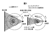
- an X-ray beam that completely covers the cross-section including the ROI is irradiated. Instead, the projection data on all straight lines passing through the cross section of the object are measured (see FIG. 1A).
- the interior CT is a method of CT imaging in which only the ROI is irradiated with X-rays and only the projection data on (all) straight lines passing through the ROI are measured to generate only the ROI image (FIG. 1). (See (b)).
- This interior CT has various advantages over conventional CT that measures unnecessary projection data wastefully. For example, (1) a significant reduction in exposure outside the ROI (sample damage), (2) a reduction in detector size and X-ray beam width, and (3) a large object that does not fit in the field of view can be taken. (4) High-resolution CT imaging can be performed in which only a small field of view of an object is irradiated with X-rays for enlarged imaging.
- Non-Patent Document 1 Natterer mathematically proves that the image reconstruction of the interior CT does not determine the solution to be “unique” (here, unique means that the image reconstruction solution is derived from the projection data). Because this non-uniqueness is known, it has been studied many approximate image reconstruction methods.
- Non-Patent Document 7 a lack of measurement data called compressed sensing is disclosed. Based on the method of signal restoration with high accuracy from the above, it is proved that if the image f (x, y) is piecewise uniform throughout the ROI S, the image reconstruction solution of the interior CT is uniquely determined did. However, the piecewise uniform means that the image is composed of a finite number of regions having a completely constant value like a numerical phantom (see FIG. 2B). This result is already known as a US patent (Patent Document 2).
- Non-Patent Document 5 In order to use the exact solution known from Non-Patent Document 5 and Non-Patent Document 6 described above, a priori knowledge about an object (an image of an image in an arbitrary small region B inside ROI S before imaging). Value) must be known. However, it is rare that the value of the image is known before shooting. In the exact solution of Non-Patent Document 7 described above, it is necessary to assume that the image is piecewise uniform over the entire ROI S, but this is not possible for a general CT image having a smooth density change. In this method, there is a risk that a smooth density change may be lost (an example is shown in FIG. 9 later).
- the present invention has been developed from a strict interior CT image reconstruction method using the above-mentioned a priori knowledge, and in the points described below, a more practical interior CT image reconstruction method.
- the purpose is to provide.
- an image reconstruction method for interior CT in which projection data is acquired by a quantum beam passing through an ROI inside an imaging target, and the projection obtained above is obtained.
- approximate reconstruction is performed by CT image reconstruction using data, and an image numerical value representing a physical quantity in the ROI based on the CT image reconstructed above is at least piecewise uniform or A region that is represented by a piecewise polynomial is specified, and the physical quantity is at least piecewise uniform or a piecewise polynomial expression that indicates the position of the specified region and the physical quantity is piecewise uniform inside or
- An interior CT image reconstruction method is provided that performs second-stage reconstruction with higher accuracy than the first-stage reconstruction using the property expressed in a piecewise polynomial form.
- the numerical value of the projection data representing the physical quantity may include absorption of the quantum beam by the imaging target, or the imaging CT
- the phase shift of the quantum beam may be included, the diffraction of the quantum beam by the imaging target may be included, or the scattering of the quantum beam by the imaging target may be included.
- the numerical value of the projection data including the phase shift, the phase shift of the quantum beam, diffraction, or diffraction is added to the detector by adding an optical element or changing its position. It is also possible to reconstruct an image using a numerical value of the projection data extracted from a set of acquired intensity data of the plurality of quantum beams and including the phase shift, diffraction, or diffraction of the extracted quantum beams. is there.
- the region in which the physical quantity specified in at least the ROI is piecewise uniform or piecewise represented by a polynomial is piecewise uniform or piecewise represented by a polynomial.
- the CT image value reconstructed by the approximate reconstruction in the first stage may be a region in which the values are piecewise uniform or piecewise represented by a polynomial, or the CT reconstructed in the first step.
- the at least piecewise uniform or piecewise polynomial region identified within the ROI of an image may be selectable within the ROI.
- the at least piecewise uniform or piecewise polynomial area specified in the ROI is an approximation of the first step. May be set manually by a human using a CT image obtained by simple reconstruction, or set by image processing using a CT image obtained by approximate reconstruction in the first stage. May be. Alternatively, it may be set in advance in the ROI by at least one of specifying from the previously acquired CT image of the imaging target, a model representing the structure of the imaging target, and specification from a priori information. Note that the at least piecewise uniform or piecewise polynomial area specified in the ROI using the CT image obtained by the approximate reconstruction in the first stage is the boundary of the ROI. A part may be formed.
- the first-stage approximate reconstruction includes conventional CT images including a filtered back projection (FBP) method, a successive approximation method, and a statistical reconstruction method.
- the second stage reconstruction may be performed by a differential backprojection Hilbert transform method, a constrained successive approximation method, and a constrained statistical reconstruction method. You may perform by at least 1 of the image reconstruction method of CT containing.
- FIG. 11 is a diagram showing an actual reconstruction example when a priori knowledge of [Result 1] to [Result 3] is used. It is a flowchart figure which shows the detail of the two step image reconstruction method of this invention. It is a figure which shows an example of the incomplete image and exact image in the two-step image reconstruction method of this invention.
- the key elements of the present invention are (1) exact reconstruction theory using much less a priori knowledge, and (2) a priori knowledge identification type image reconstruction that identifies a priori knowledge from projection data. (3) An a priori knowledge non-identification type image reconstruction method that fixes a priori knowledge without identifying it. A newly proposed image reconstruction method for this purpose will be described in detail below.
- the interior CT is compared with normal CT (see FIG. 1 (a)) that irradiates the entire object that is the subject with X-rays from an X-ray source,
- a part of a large object region of interest (ROI)
- ROI region of interest
- Example 1 is an “a priori knowledge identification type image reconstruction method” in which a priori knowledge necessary for strict image reconstruction is automatically identified from projection data and used for strict image reconstruction. This will be described below with reference to FIGS. 6 and 7A and 7B.
- FIG. 6 shows a processing flow of the image reconstruction method which is a method proposed in the present invention.
- This proposed method is a so-called two-stage image reconstruction method including a first step and a second step.
- the first first step (S61) an incomplete image including artifacts is generated using a conventional FBP method, a successive approximation image reconstruction method, a statistical image reconstruction method, or the like without a priori knowledge.
- This incomplete image includes artifacts, but since the artifacts generated in the interior CT are low frequency components, information on the boundaries of structures such as organs and tissues is accurately reflected in most cases.
- a priori information area B which is an arbitrary small area in ROI S that can be used as experimental knowledge is identified (S62). Then, in the second step, the prior information area B obtained in the first step is used for a priori knowledge, and as shown in FIG. Image reconstruction is performed with higher accuracy than the one-stage reconstruction (S63). Note that which one of [Result 1] to [Result 4] is used is determined depending on what a priori information area B can be extracted in the first step. For example, [Result 1] is definitely a constant B, and [Result 3] is definitely a piecewise uniform B. Although it is not a constant, B is close to a change in the density of a polynomial. [Result 2] is selected, and [Result 4] is selected and used if B is close to the density change of the piecewise polynomial.
- ⁇ Result 3 (Categorical uniform a priori knowledge)> As shown in FIG. 2 (a), it is known that an arbitrary small a priori information area B exists inside ROI S, and f (x, y) is known piecewise constant in B. If so, the image reconstruction solution for the interior CT is uniquely determined.
- the piecewise uniform means that, as shown in FIG. 4, B is composed of a finite number (L) of regions D 1 , D 2 ,..., D L and each region has a constant value C 1 , C 2. ,..., C L.
- the number of regions L and the values of constant values C 1 , C 2 ,..., C L may be unknown in advance, in other words, [Result 3] is obtained by reducing the a priori knowledge of [Result 1]. It has become.
- ⁇ Result 4 (a piecewise polynomial a priori knowledge)>
- an arbitrary small a priori information region B exists inside ROI S
- f (x, y) is an M-order piecewise polynomial in B.
- the image reconstruction solution for the interior CT is uniquely determined.
- the piecewise polynomial, region D 1 of the B is a finite number (L number) as shown in FIG. 4, D 2, ..., density change in the image of the l-th region consists D L f l ( x, y) has the following form:
- Patent Documents 5 and 6, Patent Document 1 a priori knowledge about an object necessary for performing strict image reconstruction is theoretically considered and described in the above prior arts. It can be seen that strict image reconstruction is possible with much less a priori knowledge than a priori knowledge.
- Non-Patent Documents 5 and 6 the same a priori knowledge of an arbitrary small region B in ROI S as [Result 1] to [Result 4] is used, but the image f (x, y) Whereas the value itself is required, in the present invention, in [Result 1] to [Result 4], the value of f (x, y) is much smaller, such as (piecewise) uniform or (piecewise) polynomial. It differs greatly only in a priori knowledge.
- Non-Patent Document 7 a priori knowledge of piecewise uniform type is used, but an unreasonable assumption is necessary that piecewise uniform throughout ROI S, not an arbitrary small region B in ROI S. It is different in point.
- FIGS. 5A to 5C show actual reconfiguration examples when the a priori knowledge of [Result 1] to [Result 3] is used. In any case, it can be seen that significant artifact reduction can be achieved with a little a priori knowledge.
- Example 2 is an “a priori knowledge automatic estimation type image reconstruction method” for identifying a priori knowledge from projection data.
- a priori knowledge necessary for strict image reconstruction of the interior CT can be much lessened.
- a priori knowledge about an object of interest is known before imaging, for example, a CT image previously captured of the same patient or an image captured with another modality. Limited to very few special cases, such as
- identifying the a priori information area B that is an arbitrary small area in ROI S that can be used as a priori knowledge in step S62 in the process flow shown in FIG. It identifies automatically without going through. It will be apparent to those skilled in the art that the automatic identification of the a priori information area can be easily realized by using, for example, an image analysis (processing) technique.
- the success or failure of the a priori knowledge automatic estimation type image reconstruction method described in the second embodiment depends on whether or not the a priori knowledge (a priori information area B) can be identified successfully in the first step.
- the step of identifying the a priori information area is somewhat complicated, there may be a desire not to perform the identifying step.
- the edge portion around ROI S A method of applying a strict image reconstruction method based on [Result 3] or [Result 4] is proposed.
- the assumption that the edge part around ROI S is piecewise uniform or piecewise polynomial is not strictly correct, so the method is only an approximate image reconstruction method, but many CT imaging In this situation, [Knowledge 3] holds, so that image reconstruction can be performed much better compared to other approximate image reconstruction methods that do not use a priori knowledge (studied before the discovery of the exact solution). Be expected.
- FIGS. 9A to 9F show specific examples of the a priori knowledge identification type image reconstruction method (Example 1) and the a priori knowledge non-identification type image reconstruction method (Example 3).
- An example of a simple simulation experiment is shown by comparison with the prior art. The chest CT image was used for the experiment, and the image was reconstructed with the heart located at the center as ROI S (see FIG. 9A).
- the user looks at the reconstructed image by the FBP method in the first step, designates the a priori information area B in ROI S, and performs the strict image reconstruction in the second step (note that The a priori knowledge was piecewise uniform with B corresponding to [Result 3]).
- the result is shown in FIG.
- image reconstruction was performed with the a priori information area B fixed to the periphery of the ROI (S (the frame type in FIG. 8C). 3] is piecewise uniform with B corresponding to). The result is shown in FIG.
- FIG. 9B shows the result of the local FBP method in which the FBP method is applied by extrapolating the missing portion of the projection data with a smooth function.
- FIG. 9D shows the results obtained by the compression sensing method (Non-Patent Document 7) that applies a total variation (TV: Total Variation), which is a constraint of the above.
- the local FBP method has a strong cupping effect and image degradation is significant, and the compression sensing method has lost considerable details and smooth density changes due to the influence of TV.
- the image can be reconstructed quite well by reducing artifacts.
- an image reconstruction method for generating an image from projection data based on the uniqueness of the solutions of [Result 1] to [Result 4] described above will be described.
- any image reconstruction method that uses a priori knowledge as a constraint condition can generate an image precisely.
- image reconstruction methods can be constructed by the following procedure. First, vectors obtained by discretizing the image f (x, y) and the projection data p (r, ⁇ ) are represented by x and b, respectively, and a projection calculation matrix that associates the projection data with the image is represented by A.
- the image x includes not only the pixels in the ROIS but also all the pixels belonging to the object existence region in the cross section (caution is required), and the projection data vector b is created by arranging all the measured values in a line. Further, an evaluation function for evaluating whether a priori knowledge is satisfied in the a priori information area B is represented by F (x). At this time, the image reconstruction can be formulated as one of the following three optimization problems.
- x ⁇ C represents a constraint condition that can be known in advance with respect to an image, and the following is often used.
- A (Support Constraint) The image x becomes zero outside the support region ⁇ OBJ that is known in advance.
- B Non-negative condition
- the component of the image x does not take a negative value.
- F (x) is a function that does not have a local optimal solution called local function (local minimum)
- local function local minimum
- iterative or non-iterative solutions to solve the above problem in the mathematical optimization and image reconstruction fields. All of these techniques are available.
- a statistical image reconstruction method with a constraint condition or a successive approximation method with a constraint condition can be used.
- an image reconstruction method can be constructed based on a later-described framework called differential back projection (DBP).
- DBP differential back projection
- the idea for designing F (x) is as follows. First, unlike the methods of Non-Patent Document 7 and Non-Patent Document 8 in which a constraint condition based on a priori knowledge is applied to the entire ROI S, the image reconstruction method of the present invention is an a priori that is an arbitrary small region in S. Constraint conditions are imposed only on information area B. In the case of [Result 1], the norm of the first derivative of f (x, y) in B is minimized because the first derivative of f (x, y) is zero in B. Or the variation (dispersion) in density change in B may be minimized.
- Table 1 shows typical F (x) examples, though not all can be given because there are various options.
- the parameter p is the norm order, and its value may be 0 ⁇ p ⁇ 2 in [Result 1] and [Result 2], but is uniform or M in [Result 3] and [Result 4]. It is necessary to use 0 ⁇ p ⁇ 1 in order to avoid that the influence of the boundary of a finite number (L) of partial areas having density changes of the following polynomial is evaluated too large.
- the F (x) shown in Table 1 with multiple candidates was tested by numerical experiments, but all of them worked well and there was no significant difference.
- ROI S is first decomposed into a set of straight lines L (u); u ⁇ U (u is a parameter representing a straight line) called a Hilbert line. Then, the DBP method is used to perform image reconstruction by reducing the image reconstruction to an inverse transformation of an integral transformation called a Hilbert transform for each Hilbert straight line L (u). However, the set of Hilbert straight lines L (u); u ⁇ U is selected so as to satisfy the following two conditions.
- Each point (x, y) of S belongs to at least one L (u).
- All L (u) intersect with the a priori information area B in which the value of f (x, y) is known in advance.
- 10 (b) and 10 (c) show how to take a typical Hilbert straight line L (u); u ⁇ U. After decomposing S into Hilbert straight lines in this way, image reconstruction is performed for each L (u) by the following processing procedure.
- ⁇ (u) represents the angle that L (u) makes with the x-axis. Note that in the region outside L (u) ⁇ S, angle truncation of projection data occurs due to truncation, and DBP cannot be calculated.
- pv represents the main value of Cauchy of integration
- points a, b, c, d, e, and f are defined as shown in FIG. That is, the image reconstruction on L (u) is reduced to the inverse transform of the Hilbert transform of equation (10).
- the observation interval [b, e] of the Hilbert transform measurement data g (t) is completely included in the support (non-zero) interval [a, f] of the image f (t), and g (t) is The range of [a, b] ⁇ [e, f] on both the left and right sides is truncated.
- the section [a, f] corresponding to the object existence area (support) is set to ⁇ OBJ
- the section [b, e] corresponding to ROI S is set to ⁇ ROI
- the section [c, d corresponding to the a priori information area B is set. ] Is represented as ⁇ PRI (see FIG. 10A).
- f (t) is uniquely determined at every point on the Hilbert straight line L (u). This holds for all Hilbert lines L (u), and the set of Hilbert lines L (u); u ⁇ U is taken to cover ROI S, so f (x, y) is unique in ROI S Determined.
- f (x, y) is uniquely determined up to the point covered by the Hilbert straight line outside ROI S, but the projection data p (r , ⁇ ) has an angular defect (not measured by 180 °), so that the value of f (x, y) is substantially stable and the image can be correctly reconstructed only at a point inside ROIS.
- [Result 1] to [Result 3] are positioned as special cases in which the polynomial degree M of the a priori knowledge used in [Result 4] and the piecewise uniform region number L are as follows.
- g (M + 1) (t) and f (M + 1) (t) are the M + 1 derivatives of g (t) and f (t), respectively, and g (M + 1) (t ) (T ⁇ ROI ) can be calculated from g (t) (t ⁇ ROI ).
- f (t) (t ⁇ PRI ) is an M-order piecewise polynomial, so f (M + 1) (t) (t ⁇ PRI ) is Dirac. It is expressed in the following form using the ⁇ function.
- the M + 1 derivative g (M + 1) (t) (t ⁇ ROI ) can be calculated from the measured projection data g (t) (t ⁇ ROI ), and g (M + 1) From the a priori knowledge that (t) (t ⁇ ROI ) and f (t) (t ⁇ PRI ) are M-order piecewise polynomials, f (M + 1) (t) ( ⁇ ⁇ t ⁇ ⁇ ) is uniquely determined. If f (M + 1) (t) ( ⁇ ⁇ t ⁇ ) is uniquely determined, f (t) (t ⁇ OBJ ) is uniquely determined by the following equation.
- the present invention can be applied to any CT imaging apparatus based on the principle of measuring the line integral value of a physical quantity distribution inside an object and generating an image of the physical quantity distribution by data processing. is there.
- CT generally refers to absorption X-ray CT that generates an image of an X-ray absorption coefficient distribution in many cases, and therefore, the image reconstruction method according to the embodiment of the present invention will be described below.
- an outline of an X-ray CT apparatus that obtains a cross-sectional image of the inside of a subject using X-rays will be described with reference to the drawings.
- FIG. 11 attached will illustrate an embodiment of the present invention in which the above-described image reconstruction method is used to measure a line integral value of a physical quantity distribution inside an object and generate an image of the physical quantity distribution by data processing.
- the whole external appearance structure of a general X-ray CT apparatus is shown. That is, the X-ray CT apparatus accommodates components such as an X-ray irradiation unit, which will be described below, and a gantry unit 1 having a substantially cylindrical hollow portion in which a subject is positioned at the center thereof, A base unit 2 having a top plate (cradle) 4 on which an object is placed, a computer (not shown here) that is a data processing device, and an image obtained are displayed.
- a console unit 3 including a display device 5 and a keyboard 6 for performing necessary input is provided.
- components constituting the X-ray CT apparatus are provided in the housing of the gantry unit 1 and the console unit 3 as shown in FIG.
- an X-ray generator 10 that irradiates a sample with X-rays in a fan shape, and a circle that detects X-rays irradiated from the apparatus and transmitted through the subject.
- the arc-shaped X-ray detection apparatus 20 is attached on, for example, a ring-shaped frame.
- a space between the X-ray generator 10 and the X-ray detector 20 is provided with a top board 30 (corresponding to reference numeral 4 in FIG. 11) on which the subject is placed (set).
- a member to which the X-ray generation device 10 and the X-ray detection device 20 are attached is a rotation drive mechanism such as a motor provided inside the gantry unit 1 via the rotation drive unit 50. Rotate in a predetermined direction at a predetermined rotation speed (see arrows in the figure).
- the top plate 30 for placing the subject is disposed so as to oppose a cylindrical space at a substantially central portion of the rotation surfaces of the X-ray generation device 10 and the X-ray detection device 20 and moves the sample placement table.
- the unit 60 It is moved by the unit 60. Furthermore, the X-ray generator 10 and the X-ray detector 20 are controlled by the rotation control of the motor, an X-ray high voltage unit 40 for generating and supplying a high voltage to the X-ray generator 10. A rotation driving unit 50 for rotating the member to which the motor is attached is provided.
- the detection signal from the X-ray detection apparatus 20 described above is input to the data collection unit 70 and collected as image data, and further reproduced by the image reproduction unit 75 as a cross-sectional image or a three-dimensional image inside the sample. Is done.
- Reference numeral 76 in the drawing denotes a storage device (image memory) used when the image reproducing unit 75 reproduces a cross-sectional image or a three-dimensional image inside the sample.
- the cross-sectional image or the three-dimensional image inside the sample reproduced by the image reproducing unit 75 is displayed on an image display unit 80 (corresponding to reference numeral 5 in FIG. 11) configured by a liquid crystal display device or the like, for example. .
- the image display unit 80 can perform input necessary for operating the apparatus.
- the apparatus may include a keyboard (corresponding to reference numeral 6 in FIG. 11), a numeric keypad, a mouse, and the like instead of the touch panel.
- reference numeral 90 in the drawing indicates a control unit (corresponding to reference numeral 3 in FIG. 11) for controlling the operation of each unit constituting the above-described X-ray CT apparatus. More specifically, for example, it is constituted by a central processing unit (CPU), a storage device (memory) such as a RAM or a ROM, and an external storage device such as an HDD, and the like. Necessary control is executed based on software and firmware for controlling the operation of each unit stored in the.
- CPU central processing unit
- storage device such as a RAM or a ROM
- HDD high-ray CT apparatus
- the image reconstruction method for interior CT according to the present invention described above is stored in a storage device (memory) such as RAM or ROM as software in the image reproduction unit 75 constituting the X-ray CT apparatus, It is executed by a central processing unit (CPU).
- a storage device such as RAM or ROM as software in the image reproduction unit 75 constituting the X-ray CT apparatus, It is executed by a central processing unit (CPU).
- CPU central processing unit
- phase X-ray CT for generating an image of a phase shift distribution from line integral data of a phase shift distribution when X-rays are irradiated
- SPECT Single Photon Emission CT
- CT single Photon Emission CT
- CT electron beam CT
- projection data using ultrasonic waves, microwaves, sound waves, seismic waves, etc.
- object or “image” refers to a spatial distribution of physical quantities to be imaged
- projection data refers to measurement data representing a line integral value on the straight line.
- the numerical value of the projection data including phase shift, quantum beam phase shift, diffraction, or diffraction is extracted from a set of intensity data of a plurality of quantum beams acquired by a detector by adding an optical element or changing its position, It is also possible to reconstruct an image using numerical values of the projection data including phase shift, diffraction, or diffraction of the extracted quantum beam.
- the present invention provides an image reconstruction method, particularly an interior CT image reconstruction method, that measures a line integral value of a physical quantity distribution inside an object and generates an image of the physical quantity distribution by data processing.
Landscapes
- Health & Medical Sciences (AREA)
- Life Sciences & Earth Sciences (AREA)
- Medical Informatics (AREA)
- Engineering & Computer Science (AREA)
- Radiology & Medical Imaging (AREA)
- Biomedical Technology (AREA)
- Biophysics (AREA)
- Nuclear Medicine, Radiotherapy & Molecular Imaging (AREA)
- Optics & Photonics (AREA)
- Pathology (AREA)
- Physics & Mathematics (AREA)
- High Energy & Nuclear Physics (AREA)
- Heart & Thoracic Surgery (AREA)
- Molecular Biology (AREA)
- Surgery (AREA)
- Animal Behavior & Ethology (AREA)
- General Health & Medical Sciences (AREA)
- Public Health (AREA)
- Veterinary Medicine (AREA)
- Apparatus For Radiation Diagnosis (AREA)
Abstract
La présente invention vise à fournir un procédé de reconstruction d'image complète pour tomodensitométrie (CT) intérieure qui utilise une connaissance a priori qui est plus pratique. Dans cette reconstruction d'image pour CT intérieure, des données de projection sont obtenues à partir de faisceaux de particules passant à travers une région d'intérêt (ROI) à l'intérieur d'un sujet étant imagé, une reconstruction approximative (première étape) est réalisée par un procédé de reconstruction d'image CT à l'aide des données de projection obtenues, une région où une valeur d'image représentant une quantité physique est au moins constante par morceaux ou représentée au moins par morceaux par une équation polynomiale est spécifiée dans la ROI sur la base de l'image CT reconstruite, et une reconstruction (seconde étape) qui est plus précise que la première étape de reconstruction est réalisée à l'aide de la position de la région spécifiée où la valeur d'image représentant une quantité physique est au moins constante par morceaux ou représentée au moins par morceaux par une équation polynomiale, et la caractéristique de la quantité physique dans cette dernière qui est au moins constante par morceaux ou représentée au moins par morceaux par une équation polynomiale.
Priority Applications (1)
| Application Number | Priority Date | Filing Date | Title |
|---|---|---|---|
| JP2018508547A JP6760611B2 (ja) | 2016-03-31 | 2017-02-15 | インテリアctの画像再構成方法 |
Applications Claiming Priority (2)
| Application Number | Priority Date | Filing Date | Title |
|---|---|---|---|
| JP2016-071935 | 2016-03-31 | ||
| JP2016071935 | 2016-03-31 |
Publications (1)
| Publication Number | Publication Date |
|---|---|
| WO2017169232A1 true WO2017169232A1 (fr) | 2017-10-05 |
Family
ID=59963945
Family Applications (1)
| Application Number | Title | Priority Date | Filing Date |
|---|---|---|---|
| PCT/JP2017/005515 Ceased WO2017169232A1 (fr) | 2016-03-31 | 2017-02-15 | Procédé de reconstruction d'image pour tomodensitométrie (ct) intérieure |
Country Status (2)
| Country | Link |
|---|---|
| JP (1) | JP6760611B2 (fr) |
| WO (1) | WO2017169232A1 (fr) |
Cited By (3)
| Publication number | Priority date | Publication date | Assignee | Title |
|---|---|---|---|---|
| JP2023117144A (ja) * | 2022-02-10 | 2023-08-23 | 株式会社島津製作所 | トモシンセシス撮影装置、画像処理装置および画像処理用プログラム |
| JP2023168124A (ja) * | 2022-05-13 | 2023-11-24 | 株式会社島津製作所 | X線ct装置および断層画像の再構成方法 |
| JP2023168125A (ja) * | 2022-05-13 | 2023-11-24 | 株式会社島津製作所 | X線ct装置および断層画像の再構成方法 |
Citations (2)
| Publication number | Priority date | Publication date | Assignee | Title |
|---|---|---|---|---|
| US20090196393A1 (en) * | 2008-02-01 | 2009-08-06 | Ge Wang | Interior Tomography and Instant Tomography by Reconstruction from Truncated Limited-Angle Projection Data |
| WO2010121043A2 (fr) * | 2009-04-15 | 2010-10-21 | Virginia Tech Intellectual Properties, Inc. | Tomographie locale assistée par ordinateur de précision fondée sur un échantillonnage compressif |
-
2017
- 2017-02-15 WO PCT/JP2017/005515 patent/WO2017169232A1/fr not_active Ceased
- 2017-02-15 JP JP2018508547A patent/JP6760611B2/ja active Active
Patent Citations (2)
| Publication number | Priority date | Publication date | Assignee | Title |
|---|---|---|---|---|
| US20090196393A1 (en) * | 2008-02-01 | 2009-08-06 | Ge Wang | Interior Tomography and Instant Tomography by Reconstruction from Truncated Limited-Angle Projection Data |
| WO2010121043A2 (fr) * | 2009-04-15 | 2010-10-21 | Virginia Tech Intellectual Properties, Inc. | Tomographie locale assistée par ordinateur de précision fondée sur un échantillonnage compressif |
Non-Patent Citations (4)
| Title |
|---|
| HIROYUKI KUDO ET AL.: "Tiny A Prioori Knowledge Solves the Interior Problem in Computed Tomography", PHYSICS IN MEDICINE AND BIOLOGY, vol. 53, no. 9, 9 April 2008 (2008-04-09), pages 2207 - 2231, XP020133966 * |
| JIANSHENG YANG ET AL.: "High Order Total Variation Minimization for Interior Tomography", INVERSE PROBLEMS, vol. 26, no. 3, 1 March 2010 (2010-03-01), pages 035013-1 - 035013-29, XP020172781, Retrieved from the Internet <URL:doi:10.1088/0266-5611/26/3/035013> * |
| JOHN PAUL WARD ET AL.: "Interior Tomography Using 1D Generalized Total Variation. Part I: Mathematical Foundation", SIAM JOURNAL ON IMAGING SCIENCES, vol. 8, no. 1, 22 January 2015 (2015-01-22), pages 226 - 247, Retrieved from the Internet <URL:https://doi.org/10.1137/140982428> * |
| M. COURDURIER ET AL.: "SOLVING THE INTERIOR PROBLEM OF COMPUTED TOMOGRAPHY USING A PRIORI KNOWLEDGE", INVERSE PROBLEMS, vol. 24, no. 6, 1 December 2008 (2008-12-01), pages 065001-1 - 065001-27, XP020142388, Retrieved from the Internet <URL:doi:10.1088/0266-5611/24/6/065001> * |
Cited By (6)
| Publication number | Priority date | Publication date | Assignee | Title |
|---|---|---|---|---|
| JP2023117144A (ja) * | 2022-02-10 | 2023-08-23 | 株式会社島津製作所 | トモシンセシス撮影装置、画像処理装置および画像処理用プログラム |
| JP7794005B2 (ja) | 2022-02-10 | 2026-01-06 | 株式会社島津製作所 | トモシンセシス撮影装置、画像処理装置および画像処理用プログラム |
| JP2023168124A (ja) * | 2022-05-13 | 2023-11-24 | 株式会社島津製作所 | X線ct装置および断層画像の再構成方法 |
| JP2023168125A (ja) * | 2022-05-13 | 2023-11-24 | 株式会社島津製作所 | X線ct装置および断層画像の再構成方法 |
| US12430823B2 (en) | 2022-05-13 | 2025-09-30 | Shimadzu Corporation | X-ray CT apparatus and reconstruction method of tomographic image |
| US12430822B2 (en) | 2022-05-13 | 2025-09-30 | Shimadzu Corporation | X-ray CT apparatus and reconstruction method of tomographic image |
Also Published As
| Publication number | Publication date |
|---|---|
| JPWO2017169232A1 (ja) | 2019-04-11 |
| JP6760611B2 (ja) | 2020-09-23 |
Similar Documents
| Publication | Publication Date | Title |
|---|---|---|
| JP7154611B2 (ja) | インテリアct画像生成方法 | |
| Hsieh et al. | Recent advances in CT image reconstruction | |
| Dong et al. | X-ray CT image reconstruction via wavelet frame based regularization and Radon domain inpainting | |
| US9824468B2 (en) | Dictionary learning based image reconstruction | |
| CN103180879B (zh) | 用于从投影数据对对象进行混合重建的设备和方法 | |
| US11670017B2 (en) | Systems and methods for reprojection and backprojection via homographic resampling transform | |
| Riblett et al. | Data‐driven respiratory motion compensation for four‐dimensional cone‐beam computed tomography (4D‐CBCT) using groupwise deformable registration | |
| US10722178B2 (en) | Method and apparatus for motion correction in CT imaging | |
| CN104821002A (zh) | 计算机断层成像中图像数据的迭代重建 | |
| JP6118324B2 (ja) | 制限角度トモグラフィーにおけるフィルターバックプロジェクションのための画像再構成方法 | |
| JP2016152916A (ja) | X線コンピュータ断層撮像装置及び医用画像処理装置 | |
| Jailin et al. | Projection-based dynamic tomography | |
| Jang et al. | Head motion correction based on filtered backprojection for x‐ray CT imaging | |
| Sunnegårdh et al. | Regularized iterative weighted filtered backprojection for helical cone‐beam CT | |
| JP6760611B2 (ja) | インテリアctの画像再構成方法 | |
| You et al. | FBP algorithms for attenuated fan-beam projections | |
| US20100232663A1 (en) | Computed tomography reconstruction for two tilted circles | |
| US8379948B2 (en) | Methods and systems for fast iterative reconstruction using separable system models | |
| US20190180481A1 (en) | Tomographic reconstruction with weights | |
| WO2023243503A1 (fr) | Procédé de reconstruction d'une image tdm intérieure, dispositif de reconstruction d'image et programme | |
| KR102329938B1 (ko) | 뉴럴 네트워크를 이용한 콘빔 단층촬영 영상 처리 방법 및 그 장치 | |
| Li et al. | Robust frame based X-ray CT reconstruction | |
| Balogh et al. | Comparison of iterative reconstruction implementations for multislice helical CT | |
| Sun et al. | Rigid motion correction for head CT imaging | |
| Tao | Rigid motion correction for head CT imaging |
Legal Events
| Date | Code | Title | Description |
|---|---|---|---|
| ENP | Entry into the national phase |
Ref document number: 2018508547 Country of ref document: JP Kind code of ref document: A |
|
| NENP | Non-entry into the national phase |
Ref country code: DE |
|
| 121 | Ep: the epo has been informed by wipo that ep was designated in this application |
Ref document number: 17773780 Country of ref document: EP Kind code of ref document: A1 |
|
| 122 | Ep: pct application non-entry in european phase |
Ref document number: 17773780 Country of ref document: EP Kind code of ref document: A1 |