WO2017169409A1 - 溶接装置および溶接方法 - Google Patents
溶接装置および溶接方法 Download PDFInfo
- Publication number
- WO2017169409A1 WO2017169409A1 PCT/JP2017/007271 JP2017007271W WO2017169409A1 WO 2017169409 A1 WO2017169409 A1 WO 2017169409A1 JP 2017007271 W JP2017007271 W JP 2017007271W WO 2017169409 A1 WO2017169409 A1 WO 2017169409A1
- Authority
- WO
- WIPO (PCT)
- Prior art keywords
- welding
- delay time
- unit
- time
- electrode
- Prior art date
- Legal status (The legal status is an assumption and is not a legal conclusion. Google has not performed a legal analysis and makes no representation as to the accuracy of the status listed.)
- Ceased
Links
Images



Classifications
-
- B—PERFORMING OPERATIONS; TRANSPORTING
- B23—MACHINE TOOLS; METAL-WORKING NOT OTHERWISE PROVIDED FOR
- B23K—SOLDERING OR UNSOLDERING; WELDING; CLADDING OR PLATING BY SOLDERING OR WELDING; CUTTING BY APPLYING HEAT LOCALLY, e.g. FLAME CUTTING; WORKING BY LASER BEAM
- B23K9/00—Arc welding or cutting
- B23K9/06—Arrangements or circuits for starting the arc, e.g. by generating ignition voltage, or for stabilising the arc
- B23K9/067—Starting the arc
-
- B—PERFORMING OPERATIONS; TRANSPORTING
- B23—MACHINE TOOLS; METAL-WORKING NOT OTHERWISE PROVIDED FOR
- B23K—SOLDERING OR UNSOLDERING; WELDING; CLADDING OR PLATING BY SOLDERING OR WELDING; CUTTING BY APPLYING HEAT LOCALLY, e.g. FLAME CUTTING; WORKING BY LASER BEAM
- B23K9/00—Arc welding or cutting
- B23K9/10—Other electric circuits therefor; Protective circuits; Remote controls
-
- B—PERFORMING OPERATIONS; TRANSPORTING
- B23—MACHINE TOOLS; METAL-WORKING NOT OTHERWISE PROVIDED FOR
- B23K—SOLDERING OR UNSOLDERING; WELDING; CLADDING OR PLATING BY SOLDERING OR WELDING; CUTTING BY APPLYING HEAT LOCALLY, e.g. FLAME CUTTING; WORKING BY LASER BEAM
- B23K9/00—Arc welding or cutting
- B23K9/16—Arc welding or cutting making use of shielding gas
- B23K9/167—Arc welding or cutting making use of shielding gas and of a non-consumable electrode
Definitions
- the present disclosure relates to a welding apparatus and a welding method.
- the present invention relates to a TIG (Tungsten Inert Gas) welding apparatus and a TIG welding method, and to replacement of an electrode attached to a TIG welding torch.
- TIG Tungsten Inert Gas
- FIG. 4 is a side view of a conventional welding torch 910 and polishing apparatus 920.
- the tip of the electrode of the welding torch 910 is polished by the polishing device 920.
- a conventional welding torch 910 includes a cylinder 911, an electrode 912, and a conduit 913 and a wire guide 914 for supplying a welding wire.
- the conventional polishing apparatus 920 includes a plurality of polishing rods 921 and a rotating body 922.
- the electrode 912 of the welding torch 910 is consumed, the tip of the electrode 912 is polished by rotating the plurality of polishing rods 921.
- the electrode 912 is replaced after a certain number of weldings or welding time has elapsed (see, for example, Patent Document 1).
- the welding apparatus of the present disclosure includes a welding torch, a welding control unit, a high frequency voltage application unit, a current detection unit, a measurement unit, and a determination unit.
- the welding torch has an electrode used for TIG welding.
- the welding control unit transmits a control signal.
- the high frequency voltage application unit receives the control signal and applies a high frequency voltage between the electrode and the base material.
- the current detector detects the arc current between the electrode and the base material.
- the measurement unit measures a delay time required from when the high frequency voltage is applied until the arc current is detected.
- the determination unit receives delay time data from the measurement unit, and determines whether the delay time is equal to or longer than a predetermined time.
- the welding method of the present disclosure includes: A first step of applying a high-frequency voltage between the base material and the electrode; A second step of detecting an arc current flowing between the base material and the electrode; A third step of measuring a delay time from the first step to the second step; A fourth step of determining whether the delay time is equal to or longer than a predetermined time; Have
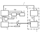
- FIG. 1 is a schematic diagram of a welding apparatus according to an embodiment.
- FIG. 2 is a graph showing the relationship between the number of arc starts of the welding apparatus according to the embodiment and the time taken from application of the high-frequency voltage to arc transition.
- FIG. 3 is a schematic diagram of an arc welding apparatus and a robot according to the embodiment.
- FIG. 4 is a side view of a conventional welding torch and polishing apparatus.
- the electrode 912 has been replaced after a certain number of weldings or welding time has elapsed.
- the consumption of the electrodes used for TIG welding is greatly influenced by the material of the base material, welding conditions (welding current and welding voltage), etc., in addition to the number of welding times and welding time. Therefore, in the conventional method for determining electrode consumption, if the electrode replacement is too early and it takes extra cost and time to replace the electrode, or if the electrode replacement is too late and the welding quality (finishing of welding) decreases. There is.
- the present disclosure can accurately polish or replace an electrode at an optimal time by accurately determining the consumption of the electrode during welding. Therefore, it is possible to provide a welding apparatus and a welding method that do not require extra cost and time for electrode replacement and have high welding quality.
- FIG. 1 is a schematic diagram of a welding apparatus 1 (arc welding apparatus) according to an embodiment.
- FIG. 2 is a graph showing the relationship between the number of arc starts of the welding apparatus 1 according to the embodiment and the time taken from application of a high-frequency voltage to arc transition.
- a method for automatically detecting when to replace the electrode 17 used for TIG welding in the welding apparatus 1 according to the embodiment of the present disclosure will be described with reference to FIGS. 1 and 2.
- the welding apparatus 1 includes a welding control unit 10, a high-frequency voltage application unit 11, a current detection unit 12, a measurement unit 13, and a determination unit 14.
- the welding control unit 10 transmits a control signal (welding output command) to the high frequency voltage application unit 11 via the signal line S31 to control the high frequency voltage application unit 11. Moreover, the welding control part 10 transmits a high frequency timing signal to the measurement part 13 via signal wire
- the high frequency timing signal is a signal indicating the timing of high frequency output. In other words, the high-frequency timing signal is a signal indicating transmission of a control signal.
- the high frequency voltage application unit 11 receives a control signal from the welding control unit 10 through the signal line S31. And the high frequency voltage application part 11 applies a high frequency voltage to a welding torch based on a control signal.
- the current detection unit 12 detects a signal indicating a welding current (arc current). Then, the current detection unit 12 transmits the detected signal to the welding control unit 10 via the signal line S32. In addition, a current timing signal (a signal indicating the timing at which the detected arc current starts to flow) is transmitted to the measurement unit 13 via the signal line S33.
- the measurement unit 13 receives a high frequency timing signal (a signal indicating the timing of high frequency output) from the welding control unit 10 and a current timing signal (a signal indicating the timing at which the arc current starts to flow) from the current detection unit 12. And the measurement part 13 measures the delay time required after receiving a high frequency timing signal until it receives a current timing signal. Further, the measured delay time data is transmitted to the determination unit 14 via the signal line S35.
- the timing at which the arc current is detected is the timing at which the arc current starts to flow.
- the determination unit 14 receives the delay time data from the measurement unit 13. And the determination part 14 determines whether delay time is more than predetermined time. Here, the determination unit 14 may transmit the determined result to the welding control unit 10 via the signal line S36. And when delay time is more than predetermined time, based on the determination result received from the determination part 14, the welding control part 10 may stop transmitting a control signal to the high frequency voltage application part 11. FIG.
- the welding control unit 10 of the welding apparatus 1 transmits a control signal (welding output command) to the high-frequency voltage application unit 11 and transmits a high-frequency timing signal of the high-frequency output to the measurement unit 13.
- the high frequency voltage application unit 11 applies a high frequency voltage between the torch 15 having the electrode 17 used for TIG welding and the base material 16. This high-frequency voltage causes air breakdown, and a current starts to flow between the torch 15 and the base material 16, and the arc discharge is started.
- the current detection unit 12 detects the arc current and transmits a current timing signal (a timing signal at which the arc current starts to flow) to the measurement unit 13.
- the measurement unit 13 measures a delay time from when the high frequency voltage is applied until the arc current is detected, and transmits the measured delay time to the determination unit 14.
- the determination unit 14 determines whether or not the delay time is equal to or longer than the predetermined time. If the delay time is equal to or longer than the predetermined time, the determination unit 14 outputs an alarm signal and transmits the alarm signal to the welding control unit 10. When receiving the alarm signal, the welding control unit 10 outputs an alarm (alarm).
- the determination unit 14 may transmit a signal for issuing an alarm to the alarm device. Further, the alarm device may or may not be included in the welding device 1. Alternatively, when the delay time is equal to or longer than the predetermined time, the determination unit 14 may transmit a signal for lighting or blinking to the lighting device.
- the lighting device may or may not be included in the welding device 1.
- the measurement part 13 and the determination part 14 may be comprised integrally.
- the determination part 14 or the welding control part 10 may be comprised integrally with the alarm device or the lighting device.
- FIG. 2 is a graph showing the relationship between the number of arc starts (horizontal axis) of the welding apparatus 1 according to the embodiment and the time (vertical axis) taken from application of a high-frequency voltage to arc transition.
- the delay time from application of a high-frequency voltage to arc transition tends to increase. This is because the electrode 17 is consumed.
- the delay time is t1, for example, 50 ms.
- the delay time is t2, for example, 100 ms.
- the longer delay time means that it is difficult to start the arc even if a high frequency is output, and it is determined that the electrode 17 is consumed. That is, the consumption of the electrode 17 can be determined by the length of the delay time taken from the reception of the high frequency timing signal to the reception of the current timing signal.
- the delay time t2 is set to a certain value (for example, 100 ms) larger than the delay time t1. If the number of arc starts increases and the arc start is n times and the delay time exceeds t2, it can be determined that it is time to replace the electrode 17 and replace it.
- the welding method of the present embodiment can automatically detect the degree of electrode wear, and can detect the timing for replacing the optimum electrode while reducing both duct time and improving welding quality. .
- FIG. 3 is a schematic diagram of a welding apparatus 1 (arc welding apparatus) and a robot 2 according to the embodiment.
- a method of automatically detecting the electrode replacement timing when the welding apparatus 1 according to the embodiment of the present disclosure and the robot 2 are connected and welding is performed using the robot will be described with reference to FIGS. 2 and 3. To do.
- the welding apparatus 1 has the same configuration as that of the first embodiment, and further includes a robot 2.
- the robot 2 includes a robot control unit 20 and a manipulator unit 21.
- the welding control unit 10 of the welding apparatus 1 performs the same function as in the first embodiment.
- the welding control unit 10 transmits the alarm signal received from the determination unit 14 to the robot control unit 20 of the robot 2 via the signal line S37.
- the high-frequency voltage application unit 11, the current detection unit 12, the measurement unit 13, and the determination unit 14 of the welding apparatus 1 perform the same functions as those in the first embodiment.
- Robot control unit 20 receives the alarm signal output from welding control unit 10 via signal line S37. Further, the robot control unit 20 transmits a control signal to the manipulator unit 21 via the signal line S38, and controls the operation of the manipulator unit 21. Further, the manipulator unit 21 attaches the torch 15 and moves the torch 15 through the connection mechanism unit M41.
- the welding apparatus 1 performs the same function as that of the first embodiment.
- the welding control unit 10 of the welding apparatus 1 receives the alarm signal output from the determination unit 14 and transmits the alarm signal to the robot control unit 20 of the robot 2.
- the robot controller 20 receives the alarm signal, the robot controller 20 outputs an alarm (alarm).
- the determination unit 14 may transmit a signal for issuing an alarm to the alarm device.
- a signal for lighting or blinking as an alarm may be transmitted to the lighting device. Therefore, the determination unit 14 outputs a signal for issuing an alarm directly or indirectly.
- the alarm device and / or the lighting device may or may not be included in the welding device 1.
- the measurement part 13 and the determination part 14 may be comprised integrally.
- the determination part 14 or the welding control part 10 may be comprised integrally with the alarm device or the lighting device.
- the method for automatically detecting the electrode replacement timing according to the present embodiment is the same as in the first embodiment.
- the welding apparatus and welding method of the present disclosure can polish or replace the electrode at an optimal time by accurately determining the consumption of the electrode used for TIG welding. Therefore, extra cost and time for electrode replacement are not required, and welding quality can be improved, which is industrially useful.
Landscapes
- Engineering & Computer Science (AREA)
- Physics & Mathematics (AREA)
- Plasma & Fusion (AREA)
- Mechanical Engineering (AREA)
- Arc Welding In General (AREA)
- Arc Welding Control (AREA)
Abstract
溶接装置(1)は、TIG溶接に用いられる電極(17)を有する溶接トーチ(15)と、溶接制御部(10)と、高周波電圧印加部(11)と、電流検出部(12)と、計測部(13)と、判定部(14)と、を有する。溶接制御部(10)は、制御信号を発信する。高周波電圧印加部(11)は、制御信号を受信し、電極(17)と母材(16)との間に高周波電圧を印加する。電流検出部(12)は、電極(17)と母材(16)との間のアーク電流を検出する。計測部(13)は、高周波電圧が印加されてから、アーク電流が検出されるまでにかかる遅延時間を計測する。判定部(14)は、計測部(13)から遅延時間のデータを受信し、遅延時間が所定時間以上かどうかを判定する。
Description
本開示は、溶接装置および溶接方法に関する。特に、TIG(Tungsten Inert Gas)溶接装置およびTIG溶接方法に関し、TIG溶接トーチに取り付けられた電極の交換に関する。
まず、従来のTIG溶接装置及びTIG溶接方法について説明する。図4は、従来の溶接トーチ910と研磨装置920の側面図である。研磨装置920により、溶接トーチ910の電極の先端が研磨される。
図4に示すように、従来の溶接トーチ910は、シリンダ911と、電極912と、溶接ワイヤを供給するためコンジット913およびワイヤガイド914と、を有する。また、従来の研磨装置920は、複数の研磨棒921と回転ボディ922とを有する。そして、溶接トーチ910の電極912が消耗されると、複数の研磨棒921を回転させて電極912の先端を研磨する。従来の溶接トーチ910では、一定の溶接回数や溶接時間が経過した後、電極912を交換している(例えば、特許文献1参照)。
本開示の溶接装置は、溶接トーチと、溶接制御部と、高周波電圧印加部と、電流検出部と、計測部と、判定部と、を有する。
溶接トーチは、TIG溶接に用いられる電極を有する。
溶接制御部は、制御信号を発信する。
高周波電圧印加部は、制御信号を受信し、電極と母材との間に高周波電圧を印加する。
電流検出部は、電極と母材との間のアーク電流を検出する。計測部は、高周波電圧が印加されてから、アーク電流が検出されるまでにかかる遅延時間を計測する。
判定部は、計測部から遅延時間のデータを受信し、遅延時間が所定時間以上かどうかを判定する。
本開示の溶接方法は、
母材と電極との間に高周波電圧を印加する第1の工程と、
母材と電極との間に流れるアーク電流を検出する第2の工程と、
第1の工程から第2の工程までの遅延時間を測定する第3の工程と、
遅延時間が所定時間以上かどうかを判定する第4の工程と、
を有する。
母材と電極との間に高周波電圧を印加する第1の工程と、
母材と電極との間に流れるアーク電流を検出する第2の工程と、
第1の工程から第2の工程までの遅延時間を測定する第3の工程と、
遅延時間が所定時間以上かどうかを判定する第4の工程と、
を有する。
従来、一定の溶接回数や溶接時間が経過した後、電極912を交換していた。しかし、TIG溶接に用いられる電極の消耗は、溶接回数や溶接時間以外にも、母材の材質や溶接条件(溶接電流や溶接電圧)などによって大きく左右される。そのため、従来の電極消耗の判断方法では、電極の交換が早すぎて電極交換のために余計な費用と時間がかかったり、電極の交換が遅すぎて溶接品質(溶接の仕上がり)が低下する場合がある。本開示は、溶接の電極の消耗を正確に判断することで、電極を最適な時期に研磨または交換できる。そのため、電極交換のための余計な費用と時間がかからず、かつ、溶接品質が高い溶接装置及び溶接方法を提供できる。
(実施の形態1)
図1は、実施の形態に係る溶接装置1(アーク溶接装置)の概略図である。図2は、実施の形態に係る溶接装置1のアークスタートの回数と、高周波電圧の印加からアーク移行までにかかる時間と、の関係を示すグラフである。図1および図2を用いて、本開示の実施の形態に係る溶接装置1におけるTIG溶接に用いられる電極17を交換する時期を自動的に検出する方法について説明する。
図1は、実施の形態に係る溶接装置1(アーク溶接装置)の概略図である。図2は、実施の形態に係る溶接装置1のアークスタートの回数と、高周波電圧の印加からアーク移行までにかかる時間と、の関係を示すグラフである。図1および図2を用いて、本開示の実施の形態に係る溶接装置1におけるTIG溶接に用いられる電極17を交換する時期を自動的に検出する方法について説明する。
図1に示すように、溶接装置1は、溶接制御部10と、高周波電圧印加部11と、電流検出部12と、計測部13と、判定部14と、を有する。
溶接制御部10は、制御信号(溶接出力命令)を、信号線S31を介して、高周波電圧印加部11に送信し、高周波電圧印加部11を制御する。また、溶接制御部10は、高周波タイミング信号を、信号線S34を介して、計測部13に送信する。さらに、溶接制御部10は、電流検出部12で検出された溶接電流を示す信号と、判定部14から出力した判定信号と、を受信する。ここで、高周波タイミング信号とは、高周波出力のタイミングを示す信号である。言い替えれば、高周波タイミング信号とは、制御信号の発信を示す信号である。
高周波電圧印加部11は、溶接制御部10から、信号線S31を介して、制御信号を受信する。そして、高周波電圧印加部11は、制御信号に基づいて、溶接トーチに高周波電圧を印加する。
電流検出部12は、溶接電流(アーク電流)を示す信号を検出する。そして、電流検出部12は、その検出した信号を、信号線S32を介して溶接制御部10に送信する。また、電流タイミング信号(検出したアーク電流が流れ始めるタイミングを示す信号)を、信号線S33を介して、計測部13に送信する。
計測部13は、溶接制御部10から高周波タイミング信号(高周波出力のタイミングを示す信号)と、電流検出部12から電流タイミング信号(アーク電流が流れ始めるタイミングを示す信号)と、を受信する。そして、計測部13は、高周波タイミング信号を受信してから電流タイミング信号を受信するまでにかかる遅延時間を計測する。また、計測した遅延時間のデータを信号線S35を介して、判定部14に送信する。本実施の形態では、アーク電流が検出されたタイミングを、アーク電流が流れ始めるタイミングとしている。
判定部14は、計測部13からの遅延時間のデータを受信する。そして、判定部14は、遅延時間が所定時間以上であるかどうかを判定する。ここで、判定部14は、判定した結果を信号線S36を介して溶接制御部10に送信してもよい。そして、遅延時間が所定時間以上の場合、判定部14から受け取った判定結果に基づいて、溶接制御部10は、制御信号を高周波電圧印加部11に送信するのを停止してもよい。
以上のような構成により、溶接装置1の溶接制御部10は、制御信号(溶接出力命令)を高周波電圧印加部11に送信し、並びに、高周波出力の高周波タイミング信号を計測部13に送信する。また、高周波電圧印加部11によって、TIG溶接に用いられる電極17を有するトーチ15と、母材16との間に高周波電圧が印加される。この高周波電圧により空気の絶縁破壊が発生し、トーチ15と、母材16と、の間に電流が流れ始めてアーク放電に移行する。アーク放電に移行すると、電流検出部12は、アーク電流を検出し、電流タイミング信号(アーク電流が流れ始めるタイミング信号)を計測部13に送信する。計測部13は、高周波電圧が印加されてからアーク電流が検出されるまでの遅延時間を測定し、判定部14に送信する。判定部14は、遅延時間が所定時間以上であるかどうかを判定し、遅延時間が所定時間以上であれば、アラーム信号を出力し、溶接制御部10に送信する。溶接制御部10は、アラーム信号を受信したら、アラーム(警報)を出力させる。ここで、判定部14は、警報を発するための信号を警報装置に送信してもよい。また、警報装置は、溶接装置1に含まれていてもよく、含まれていなくてもよい。あるいは、遅延時間が所定時間以上の場合、判定部14は、点灯や点滅などのための信号を点灯装置に送信してもよい。ここで、点灯装置は、溶接装置1に含まれていてもよく、含まれていなくてもよい。また、計測部13と判定部14は一体に構成されていてもよい。さらに、判定部14あるいは、溶接制御部10が、警報装置あるいは点灯装置と一体に構成されていてもよい。以上の構成により、作業者は電極17の消耗を知ることができる。
次に、図2を用いて、本実施の形態に係る電極17(溶接電極)を交換する時期を自動的に検出する方法について説明する。
図2は、実施の形態に係る溶接装置1のアークスタートの回数(横軸)と、高周波電圧が印加されてからアーク移行までにかかる時間(縦軸)と、の関係を示すグラフである。
図2に示すように、アークスタートの回数が増えることによって、高周波電圧が印加されてからアーク移行までにかかる遅延時間が長くなる傾向がある。これは、電極17が消耗されるからである。図2において、アークスタート回数がn1(例えば1回目)の場合、遅延時間はt1であり、例えば50msである。また、アークスタート回数がnn(例えばn回目)の場合、遅延時間はt2となり、例えば100msとなる。遅延時間が長くなっているということは、つまり、高周波を出力してもアークスタートしにくくなっているということであり、電極17が消耗されていると判断される。すなわち、電極17の消耗は、高周波タイミング信号を受信してから電流タイミング信号を受信するまでにかかる遅延時間の長さにより判断できる。実際には、例えば、遅延時間t2を、遅延時間t1より大きいある一定値(例えば100ms)に設定しておく。そして、アークスタートの回数が増えることによって、アークスタートがn回目で遅延時間がt2を超えた場合、電極17が消耗されて交換する時期であると判断できる。
以上の構成により、本実施形態の溶接方法は、電極の消耗度合を自動的に検出し、ダクトタイムの短縮と、溶接品質の向上と、を両立して最適な電極を交換するタイミングを検出できる。
(実施の形態2)
図3は、実施の形態に係る溶接装置1(アーク溶接装置)と、ロボット2の概略図である。本開示の実施形態に係る溶接装置1と、ロボット2と、を接続し、ロボットを用いて溶接を行う場合、電極交換タイミングを自動的に検出する方法について、図2および図3を用いて説明する。
図3は、実施の形態に係る溶接装置1(アーク溶接装置)と、ロボット2の概略図である。本開示の実施形態に係る溶接装置1と、ロボット2と、を接続し、ロボットを用いて溶接を行う場合、電極交換タイミングを自動的に検出する方法について、図2および図3を用いて説明する。
溶接装置1は、実施の形態1と同じ構成を有し、さらにロボット2を有する。ロボット2は、ロボット制御部20と、マニピュレータ部21と、を有する。
溶接装置1の溶接制御部10は、実施の形態1と同じ機能を果たす。それに加え、溶接制御部10は、信号線S37を介して、判定部14から受信したアラーム信号をロボット2のロボット制御部20に送信する。また、溶接装置1の高周波電圧印加部11と、電流検出部12と、計測部13と、判定部14とは、実施の形態1と同じ機能を果たす。
ロボット制御部20は、信号線S37を介して、溶接制御部10から出力したアラーム信号を受信する。また、ロボット制御部20は、信号線S38を介して、マニピュレータ部21に制御信号を送信し、マニピュレータ部21の動作を制御する。また、マニピュレータ部21は、接続機構部M41を介して、トーチ15を装着し、トーチ15を移動させる。
以上のような構成により、溶接装置1は、実施の形態1と同じ機能を果たす。それに加え、溶接装置1の溶接制御部10は、判定部14から出力したアラーム信号を受信し、そのアラーム信号をロボット2のロボット制御部20に送信する。ロボット制御部20は、アラーム信号を受信したら、アラーム(警報)を出力させる。
また、実施の形態1と同様に、判定部14は、警報を発するための信号を警報装置に送信してもよい。あるいは、遅延時間が所定時間以上の場合、警報としての、点灯や点滅などのための信号を点灯装置に送信してもよい。したがって、判定部14は、直接的または間接的に警報を発するための信号を出力する。
ここで、警報装置および/あるいは点灯装置は、溶接装置1に含まれていてもよく、含まれていなくてもよい。また、計測部13と判定部14は一体に構成されていてもよい。さらに、判定部14あるいは、溶接制御部10が、警報装置あるいは点灯装置と一体に構成されていてもよい。以上の構成により、作業者は電極17の消耗を知ることができる。
本実施の形態に係る電極交換のタイミングを自動的に検出する方法は、実施の形態1と同様である。
本開示の溶接装置および溶接方法は、TIG溶接に用いられる電極の消耗を正確に判断することで、電極を最適な時期に研磨または交換できる。そのため、電極交換のための余計な費用と時間がかからず、かつ、溶接品質を高くでき、産業上有用である。
1 溶接装置
2 ロボット
10 溶接制御部
11 高周波電圧印加部
12 電流検出部
13 計測部
14 判定部
15 トーチ
16 母材
17 電極
20 ロボット制御部
21 マニピュレータ部
910 溶接トーチ
911 シリンダ
912 電極
913 コンジット
914 ワイヤガイド
920 研磨装置
921 研磨棒
922 回転ボディ
S31~S38 信号線
M41 接続機構部
2 ロボット
10 溶接制御部
11 高周波電圧印加部
12 電流検出部
13 計測部
14 判定部
15 トーチ
16 母材
17 電極
20 ロボット制御部
21 マニピュレータ部
910 溶接トーチ
911 シリンダ
912 電極
913 コンジット
914 ワイヤガイド
920 研磨装置
921 研磨棒
922 回転ボディ
S31~S38 信号線
M41 接続機構部
Claims (11)
- TIG溶接に用いられる電極を有する溶接トーチと、
制御信号を発信する溶接制御部と、
前記制御信号を受信し、前記電極と母材との間に高周波電圧を印加する高周波電圧印加部と、
前記電極と前記母材との間のアーク電流を検出する電流検出部と、
前記高周波電圧が印加されてから、前記アーク電流が検出されるまでにかかる遅延時間を計測する計測部と、
前記計測部から前記遅延時間のデータを受信し、前記遅延時間が所定時間以上かどうかを判定する判定部と、
を備えた、
溶接装置。 - 前記計測部は、
前記溶接制御部から、前記制御信号の発信を示す高周波タイミング信号を受信した時点を、前記高周波電圧が印加された時点とし、
前記電流検出部から、前記アーク電流の検出を示す電流タイミング信号を受信した時点を、前記アーク電流が検出された時点とし、
前記高周波タイミング信号を受信してから、前記電流タイミング信号を受信するまでにかかる時間を前記遅延時間とする
請求項1記載の溶接装置。 - 前記判定部は、前記遅延時間が所定時間以上の場合、警報を発するための信号を警報装置に送信する
請求項1記載の溶接装置。 - 前記判定部は、前記遅延時間が所定時間以上の場合、点灯させるための信号を点灯装置に送信する
請求項1記載の溶接装置。 - 前記判定部は、前記遅延時間が所定時間以上かどうかを判定した判定結果を、前記溶接制御部に送信する
請求項1記載の溶接装置。 - 前記溶接制御部は、前記判定部から受け取った前記判定結果に基づいて、前記制御信号を前記高周波電圧印加部に送信するのを停止する
請求項5記載の溶接装置。 - 前記計測部と前記判定部は一体に構成されている
請求項1記載の溶接装置。 - 母材と電極との間に高周波電圧を印加する第1の工程と、
前記母材と前記電極との間に流れるアーク電流を検出する第2の工程と、
前記第1の工程から前記第2の工程までの遅延時間を測定する第3の工程と、
前記遅延時間が所定時間以上かどうかを判定する第4の工程と、
を備えた
溶接方法。 - 前記遅延時間は、前記高周波電圧が印加された時点から前記アーク電流が検出された時点までである
請求項8記載の溶接方法。 - 前記遅延時間が前記所定時間以上の場合、警報を発する第5の工程を、
さらに備える
請求項8記載の溶接方法。 - 前記遅延時間が前記所定時間以上の場合、点灯する第5の工程を、
さらに備える
請求項8記載の溶接方法。
Priority Applications (2)
| Application Number | Priority Date | Filing Date | Title |
|---|---|---|---|
| JP2018508804A JP6765037B2 (ja) | 2016-03-29 | 2017-02-27 | 溶接装置および溶接方法 |
| CN201780018836.6A CN108778597B (zh) | 2016-03-29 | 2017-02-27 | 焊接装置以及焊接方法 |
Applications Claiming Priority (2)
| Application Number | Priority Date | Filing Date | Title |
|---|---|---|---|
| JP2016065330 | 2016-03-29 | ||
| JP2016-065330 | 2016-03-29 |
Publications (1)
| Publication Number | Publication Date |
|---|---|
| WO2017169409A1 true WO2017169409A1 (ja) | 2017-10-05 |
Family
ID=59963128
Family Applications (1)
| Application Number | Title | Priority Date | Filing Date |
|---|---|---|---|
| PCT/JP2017/007271 Ceased WO2017169409A1 (ja) | 2016-03-29 | 2017-02-27 | 溶接装置および溶接方法 |
Country Status (3)
| Country | Link |
|---|---|
| JP (1) | JP6765037B2 (ja) |
| CN (1) | CN108778597B (ja) |
| WO (1) | WO2017169409A1 (ja) |
Cited By (2)
| Publication number | Priority date | Publication date | Assignee | Title |
|---|---|---|---|---|
| CN108872650A (zh) * | 2018-06-15 | 2018-11-23 | 周建秀 | 多用途探测电极 |
| WO2021149570A1 (ja) * | 2020-01-23 | 2021-07-29 | パナソニックIpマネジメント株式会社 | 溶接装置 |
Families Citing this family (3)
| Publication number | Priority date | Publication date | Assignee | Title |
|---|---|---|---|---|
| JP7265308B2 (ja) * | 2019-08-30 | 2023-04-26 | 株式会社ダイヘン | 溶接装置 |
| CN111906409B (zh) * | 2020-08-15 | 2021-12-07 | 浙江劳士顿科技股份有限公司 | 一种电焊机引弧装置及其引弧方法 |
| CN114131155B (zh) * | 2021-12-10 | 2023-09-22 | 唐山松下产业机器有限公司 | 焊接装置及钨极清理方法 |
Citations (4)
| Publication number | Priority date | Publication date | Assignee | Title |
|---|---|---|---|---|
| JPS6224864A (ja) * | 1985-07-26 | 1987-02-02 | Koike Sanso Kogyo Co Ltd | プラズマ切断装置電極の使用限界を検知する方法および装置 |
| JPH0619972U (ja) * | 1992-06-26 | 1994-03-15 | 株式会社ダイヘン | Tig溶接機 |
| JPH10166145A (ja) * | 1996-12-03 | 1998-06-23 | Matsushita Electric Ind Co Ltd | Tig溶接機 |
| US20160129514A1 (en) * | 2014-11-07 | 2016-05-12 | Illinois Tool Works Inc. | Welding Type Power Supply For TIG Starts |
Family Cites Families (4)
| Publication number | Priority date | Publication date | Assignee | Title |
|---|---|---|---|---|
| FR2906169B1 (fr) * | 2006-09-25 | 2009-06-05 | Air Liquide | Procede de detection automatique de l'usure d'une electrode de soudage |
| US8723080B2 (en) * | 2009-07-10 | 2014-05-13 | Panasonic Corporation | Arc welding control method and arc welding apparatus |
| CN102380691B (zh) * | 2010-08-31 | 2014-11-05 | 株式会社大亨 | 消耗电极电弧焊接的缩颈检测控制方法 |
| JP5908802B2 (ja) * | 2012-06-19 | 2016-04-26 | 株式会社ダイヘン | プラズマアーク溶接方法およびプラズマアーク溶接システム |
-
2017
- 2017-02-27 WO PCT/JP2017/007271 patent/WO2017169409A1/ja not_active Ceased
- 2017-02-27 JP JP2018508804A patent/JP6765037B2/ja active Active
- 2017-02-27 CN CN201780018836.6A patent/CN108778597B/zh active Active
Patent Citations (4)
| Publication number | Priority date | Publication date | Assignee | Title |
|---|---|---|---|---|
| JPS6224864A (ja) * | 1985-07-26 | 1987-02-02 | Koike Sanso Kogyo Co Ltd | プラズマ切断装置電極の使用限界を検知する方法および装置 |
| JPH0619972U (ja) * | 1992-06-26 | 1994-03-15 | 株式会社ダイヘン | Tig溶接機 |
| JPH10166145A (ja) * | 1996-12-03 | 1998-06-23 | Matsushita Electric Ind Co Ltd | Tig溶接機 |
| US20160129514A1 (en) * | 2014-11-07 | 2016-05-12 | Illinois Tool Works Inc. | Welding Type Power Supply For TIG Starts |
Cited By (6)
| Publication number | Priority date | Publication date | Assignee | Title |
|---|---|---|---|---|
| CN108872650A (zh) * | 2018-06-15 | 2018-11-23 | 周建秀 | 多用途探测电极 |
| WO2021149570A1 (ja) * | 2020-01-23 | 2021-07-29 | パナソニックIpマネジメント株式会社 | 溶接装置 |
| JPWO2021149570A1 (ja) * | 2020-01-23 | 2021-07-29 | ||
| CN114929420A (zh) * | 2020-01-23 | 2022-08-19 | 松下知识产权经营株式会社 | 焊接装置 |
| CN114929420B (zh) * | 2020-01-23 | 2024-04-05 | 松下知识产权经营株式会社 | 焊接装置 |
| JP7595239B2 (ja) | 2020-01-23 | 2024-12-06 | パナソニックIpマネジメント株式会社 | 溶接装置 |
Also Published As
| Publication number | Publication date |
|---|---|
| CN108778597B (zh) | 2021-06-25 |
| JPWO2017169409A1 (ja) | 2019-02-14 |
| CN108778597A (zh) | 2018-11-09 |
| JP6765037B2 (ja) | 2020-10-07 |
Similar Documents
| Publication | Publication Date | Title |
|---|---|---|
| WO2017169409A1 (ja) | 溶接装置および溶接方法 | |
| US8592719B2 (en) | System and method for identifying welding consumable wear | |
| CN104768694B (zh) | 在焊接操作期间检测熔滴从焊丝的分离的方法 | |
| EP3160675B1 (en) | System and method for controlling wire feed speed | |
| US20150158109A1 (en) | Torch for electric arc welding or plasma cutting system | |
| JP2010502446A (ja) | 溶接プロセスを実施するための溶接方法 | |
| JP2012501852A (ja) | 自動ワイヤ供給システム | |
| CA2959889C (en) | Methods and apparatus to control hot-start weld current for arc ignition | |
| CN100457356C (zh) | 控制和/或调节焊接过程的方法 | |
| US11872659B2 (en) | Welding device and welding method with self-setting welding wire feed speed | |
| KR101631401B1 (ko) | 두 개의 용접 토치를 갖는 용접 장치와, 두 개의 용접 공정을 사용하는 용접 방법 | |
| ES2650397T3 (es) | Método de supervisión de la vida útil de la punta de contacto de soldadura GMAW pulsada en función de parámetros representativos | |
| CN105364267A (zh) | 电弧焊接装置、系统、方法和被焊接物的制造方法 | |
| CN112423926B (zh) | 包括消耗性焊丝的电弧焊接方法 | |
| CN112334262B (zh) | 点焊机 | |
| CN104439613B (zh) | 电弧焊接装置、方法和系统以及被焊接部件 | |
| JP6320851B2 (ja) | 消耗電極式アーク溶接のアークスタート制御方法、溶接装置 | |
| CN113677472B (zh) | 带有测量值同步的焊接方法和焊接组件 | |
| JP4151777B2 (ja) | ホットワイヤ溶接方法および装置 | |
| KR101550849B1 (ko) | 서브머지드 아크 용접용 감시 장치 | |
| KR101756297B1 (ko) | 싱글 케이블의 상태를 측정하여 용접성을 개선한 용접 시스템 | |
| JP5812685B2 (ja) | コンデンサ放電型スタッド溶接用溶接ガンの良否判定方法及び良否判定装置 | |
| KR101222440B1 (ko) | 용접전류 검출장치 | |
| KR102814993B1 (ko) | 소모전극식 아크용접에서 공정신호에 의한 용접결함 평가 방법 및 그 장치 | |
| JP7258445B2 (ja) | 抵抗溶接機の制御装置、溶接部の通電状態監視方法及び良否判定方法 |
Legal Events
| Date | Code | Title | Description |
|---|---|---|---|
| WWE | Wipo information: entry into national phase |
Ref document number: 2018508804 Country of ref document: JP |
|
| NENP | Non-entry into the national phase |
Ref country code: DE |
|
| 121 | Ep: the epo has been informed by wipo that ep was designated in this application |
Ref document number: 17773954 Country of ref document: EP Kind code of ref document: A1 |
|
| 122 | Ep: pct application non-entry in european phase |
Ref document number: 17773954 Country of ref document: EP Kind code of ref document: A1 |