WO2017169901A1 - Récipient de revêtement et outil de revêtement - Google Patents
Récipient de revêtement et outil de revêtement Download PDFInfo
- Publication number
- WO2017169901A1 WO2017169901A1 PCT/JP2017/010919 JP2017010919W WO2017169901A1 WO 2017169901 A1 WO2017169901 A1 WO 2017169901A1 JP 2017010919 W JP2017010919 W JP 2017010919W WO 2017169901 A1 WO2017169901 A1 WO 2017169901A1
- Authority
- WO
- WIPO (PCT)
- Prior art keywords
- mouth
- bottom wall
- base
- application container
- finger
- Prior art date
- Legal status (The legal status is an assumption and is not a legal conclusion. Google has not performed a legal analysis and makes no representation as to the accuracy of the status listed.)
- Ceased
Links
Images


Classifications
-
- A—HUMAN NECESSITIES
- A61—MEDICAL OR VETERINARY SCIENCE; HYGIENE
- A61M—DEVICES FOR INTRODUCING MEDIA INTO, OR ONTO, THE BODY; DEVICES FOR TRANSDUCING BODY MEDIA OR FOR TAKING MEDIA FROM THE BODY; DEVICES FOR PRODUCING OR ENDING SLEEP OR STUPOR
- A61M35/00—Devices for applying media, e.g. remedies, on the human body
- A61M35/003—Portable hand-held applicators having means for dispensing or spreading integral media
-
- B—PERFORMING OPERATIONS; TRANSPORTING
- B65—CONVEYING; PACKING; STORING; HANDLING THIN OR FILAMENTARY MATERIAL
- B65D—CONTAINERS FOR STORAGE OR TRANSPORT OF ARTICLES OR MATERIALS, e.g. BAGS, BARRELS, BOTTLES, BOXES, CANS, CARTONS, CRATES, DRUMS, JARS, TANKS, HOPPERS, FORWARDING CONTAINERS; ACCESSORIES, CLOSURES, OR FITTINGS THEREFOR; PACKAGING ELEMENTS; PACKAGES
- B65D83/00—Containers or packages with special means for dispensing contents
- B65D83/76—Containers or packages with special means for dispensing contents for dispensing fluent contents by means of a piston
- B65D83/765—Containers or packages with special means for dispensing contents for dispensing fluent contents by means of a piston the piston being a follower-piston and the dispensing means comprising a hand-operated pressure device at the opposite part of the container
-
- B—PERFORMING OPERATIONS; TRANSPORTING
- B05—SPRAYING OR ATOMISING IN GENERAL; APPLYING FLUENT MATERIALS TO SURFACES, IN GENERAL
- B05C—APPARATUS FOR APPLYING FLUENT MATERIALS TO SURFACES, IN GENERAL
- B05C17/00—Hand tools or apparatus using hand held tools, for applying liquids or other fluent materials to, for spreading applied liquids or other fluent materials on, or for partially removing applied liquids or other fluent materials from, surfaces
- B05C17/005—Hand tools or apparatus using hand held tools, for applying liquids or other fluent materials to, for spreading applied liquids or other fluent materials on, or for partially removing applied liquids or other fluent materials from, surfaces for discharging material from a reservoir or container located in or on the hand tool through an outlet orifice by pressure without using surface contacting members like pads or brushes
- B05C17/00503—Details of the outlet element
-
- B—PERFORMING OPERATIONS; TRANSPORTING
- B65—CONVEYING; PACKING; STORING; HANDLING THIN OR FILAMENTARY MATERIAL
- B65D—CONTAINERS FOR STORAGE OR TRANSPORT OF ARTICLES OR MATERIALS, e.g. BAGS, BARRELS, BOTTLES, BOXES, CANS, CARTONS, CRATES, DRUMS, JARS, TANKS, HOPPERS, FORWARDING CONTAINERS; ACCESSORIES, CLOSURES, OR FITTINGS THEREFOR; PACKAGING ELEMENTS; PACKAGES
- B65D47/00—Closures with filling and discharging, or with discharging, devices
- B65D47/42—Closures with filling and discharging, or with discharging, devices with pads or like contents-applying means
-
- B—PERFORMING OPERATIONS; TRANSPORTING
- B65—CONVEYING; PACKING; STORING; HANDLING THIN OR FILAMENTARY MATERIAL
- B65D—CONTAINERS FOR STORAGE OR TRANSPORT OF ARTICLES OR MATERIALS, e.g. BAGS, BARRELS, BOTTLES, BOXES, CANS, CARTONS, CRATES, DRUMS, JARS, TANKS, HOPPERS, FORWARDING CONTAINERS; ACCESSORIES, CLOSURES, OR FITTINGS THEREFOR; PACKAGING ELEMENTS; PACKAGES
- B65D83/00—Containers or packages with special means for dispensing contents
- B65D83/14—Containers for dispensing liquid or semi-liquid contents by internal gaseous pressure, i.e. aerosol containers comprising propellant
- B65D83/38—Details of the container body
Definitions
- the present invention relates to an applicator.
- Patent Document 1 discloses an applicator that includes an application container that stores a chemical solution and an application unit connected to the application container.
- the application container has a bottom wall, a trunk portion having a shape rising from an outer edge of the bottom wall, and a mouth portion connected to the trunk portion.
- the mouth portion is open in a direction intersecting the direction orthogonal to the bottom wall.
- the body portion includes a base portion connected to the bottom wall, a diameter-reducing portion that gradually decreases in diameter from the base portion toward the mouth portion, and a bottom wall located on the basis of the center axis in a direction orthogonal to the center axis of the mouth portion.
- a dorsal neck portion that connects the reduced diameter portion and the mouth portion at a position opposite to the side to be operated.
- An object of the present invention is to provide an application container and an applicator that can reduce the impact force caused by a chemical when the posture is changed from an upward posture to a downward posture.
- the present invention is an application container that can store a chemical solution, and includes a bottom wall, a body portion that has a shape rising from an outer edge of the bottom wall, and the body portion among the body portions. And a mouth opening in a direction intersecting with the direction orthogonal to the bottom wall, the trunk portion being connected to the bottom wall.
- a reduced diameter portion that gradually decreases in diameter from the base portion toward the mouth portion, an interposed portion that is interposed between the reduced diameter portion and the mouth portion, and is orthogonal to the central axis of the mouth portion
- a back side neck portion connecting the interposition portion and the mouth portion at a position opposite to the side on which the bottom wall is located with respect to the central axis with respect to the direction to be
- the inner surface of the first ventral boundary between the base portion and the reduced diameter portion on the same side as the side where the portion is open is outward
- the inner surface of the second ventral boundary between the reduced diameter portion and the interposition portion on the same side as the side where the mouth portion is open. Provides a coating container having a shape that is curved to be convex inward.
- the inner surface of the first ventral boundary is curved so as to protrude outward
- the inner surface of the second ventral boundary is curved so as to protrude inward. Is suppressed from rising (from the position where the mouth is positioned above the bottom wall) to the down (from the position where the mouth is positioned below the bottom wall).
- the chemical solution that has passed through the second ventral boundary is rectified by this intervening portion. Therefore, the impact force generated when the chemical solution collides with the inner surface of the back neck portion is reduced. Accordingly, the user may drop the application container when the application container is changed from the upward posture to the downward posture with the portion near the bottom wall of the base portion held by the three fingers of the thumb, the index finger, and the middle finger. It is suppressed.
- the inner peripheral surface of the mouth part is formed with a groove part that is recessed so as to protrude outward in the radial direction of the mouth part.
- the base is formed on the side of the base opposite to the side where the mouth is open, and has a shape projecting outward in the radial direction of the base or indented inward. It is preferable to have a back finger-hanging portion having a shape.
- the index finger can be hung on the rear finger-holding portion when the base portion near the bottom wall is gripped by the three fingers of the thumb, the index finger, and the middle finger, so the application container is changed from the upward posture to the downward posture. In this case, the user is more reliably prevented from dropping the application container.
- the back finger-hanging portion has a shape protruding outward in the radial direction of the base portion, and the back finger-hanging portion is mounted outside the outer edge of the bottom wall in the radial direction of the base portion. It is preferable to have a back lower overhanging surface that can contact the mounting surface.
- the rear lower overhanging surface contacts the placement surface outside the outer edge of the bottom wall, so that only the outer surface of the bottom wall is placed.
- the application container is prevented from falling when the application container is placed on the placement surface.
- the base is formed on both sides of a direction perpendicular to a direction connecting the side where the mouth is open and the opposite side of the base, and the base is outside in the radial direction of the base. It is preferable to have a pair of side finger hooks having a shape protruding in the direction or a shape recessed inward.
- the thumb and the middle finger can be hung on the pair of side finger grips when gripping the portion of the base near the bottom wall with the three fingers of the thumb, the index finger and the middle finger. It is more reliably suppressed that the user drops the application container when changing to the downward posture.
- the pair of side surface finger hanging portions has a shape protruding outward in the radial direction of the base portion, and the pair of side surface finger hanging portions are formed from an outer edge of the bottom wall in the radial direction of the base portion. Further, it is preferable that the outer side has a side underhanging surface that can come into contact with the mounting surface.
- the side surface overhanging surface is in contact with the placement surface outside the outer edge of the bottom wall, so that only the outer surface of the bottom wall is placed. Compared with the case of contacting the surface, the application container is prevented from falling when the application container is placed on the placement surface.
- the present invention provides an applicator provided with the applicator container and an applicator connected to the mouth of the applicator container and capable of applying a chemical solution in the applicator container.
- an application container and an applicator that can reduce the impact force caused by a chemical solution when the posture is changed from an upward posture to a downward posture.
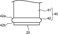
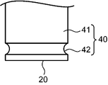
- FIG. 3 is a cross-sectional view taken along line III-III in FIG. 2. It is a top view of an application container. It is a figure which shows the modification of a back finger hook part and a pair of finger hook part. It is a figure which shows the modification of a back finger hook part and a pair of finger hook part.
- the present application device 1 includes an application container 10 and an application unit 90. 3 and 4, the application unit 90 is not shown.
- the application container 10 has a bottom wall 20, a body part 30, and a mouth part 80.
- the bottom wall 20 has a shape that curves so as to protrude inward (upward in FIG. 3).
- the trunk portion 30 has a shape that rises from the outer edge of the bottom wall 20.
- the trunk portion 30 has a shape extending along a direction orthogonal to the bottom wall 20.
- the trunk portion 30 includes a base portion 40, a reduced diameter portion 50, an interposition portion 60, and a back side neck portion 70.
- the base 40 is connected to the bottom wall 20.
- the base 40 has a substantially cylindrical shape. Details of the base 40 will be described later.
- the reduced diameter portion 50 gradually decreases in diameter as it goes from the base portion 40 to the mouth portion 80. Specifically, the diameter-reduced portion 50 is reduced in diameter on the same side (left side in FIGS. 1 and 3) as the side on which the mouth portion 80 is opened. The diameter of the portion 50 is reduced so as to approach the portion on the opposite side (the right side in FIGS. 1 and 3) to the side where the mouth portion 80 is open.
- the same side as the side where the mouth part 80 is opened in the trunk part 30 is referred to as the ventral side
- the opposite side of the trunk part 30 from the side where the mouth part 80 is opened is referred to as the back side.
- the inner surface of the first ventral boundary 31 between the base 40 and the reduced diameter portion 50 on the ventral side has a shape that curves so as to protrude outward.
- the interposition part 60 is interposed between the reduced diameter part 50 and the mouth part 80.
- the part on the ventral side of the interposition part 60 has a shape that curves so as to be convex inward.
- a portion on the ventral side of the interposition part 60 is connected to the mouth part 80.
- the inner surface of the second ventral boundary 32 between the reduced diameter portion 50 and the interposition portion 60 on the ventral side has a shape that curves so as to be convex inward.
- the back side neck portion 70 connects the interposition portion 60 and the mouth portion 80 at a position opposite to the side where the bottom wall 20 is located with respect to the center axis A in a direction orthogonal to the center axis A of the mouth portion 80. .
- the dorsal neck 70 connects the interposition part 60 and the mouth part 80 on the dorsal side.
- the mouth 80 is connected to the end of the body 30 opposite to the bottom wall 20 (upper side in FIG. 1).
- the mouth 80 is open in a direction intersecting the direction orthogonal to the bottom wall 20.
- a groove portion 82 is formed in the inner peripheral surface of the mouth portion 80 so as to be convex outward in the radial direction of the mouth portion 80.
- the groove 82 may be omitted.
- a cap can be attached to the mouth portion 80.
- the application unit 90 can be detachably connected to the mouth 80.
- the application unit 90 can apply the chemical solution in the application container 10.
- the base 40 includes a base main body 41 having a cylindrical outer peripheral surface, and a finger hooking portion 42 for a user to hold a finger.
- the finger hanging portion 42 is formed in a portion of the base main body 41 in the vicinity of the bottom wall 20.
- the finger hanging portion 42 has a shape that protrudes outward from the outer peripheral surface of the base body 41 in the radial direction of the base body 41.
- the finger hooks 42 are continuously connected along the circumferential direction of the base body 41.
- the outer shape of the finger hanging portion 42 is slightly more than the outer shapes of the base main body 41, the reduced diameter portion 50, the interposition portion 60, the back side neck portion 70, the mouth portion 80, and the application portion 90. It is set large.
- the finger hanging part 42 connects the bottom wall 20 and the mouth part 80 with the upper projecting surface 42a formed on the side close to the mouth part 80 in the direction connecting the bottom wall 20 and the mouth part 80 (vertical direction in FIG. 1). And a lower projecting surface 42b formed on the side closer to the bottom wall 20 in the direction.
- the upper overhanging surface 42 a has a shape that gradually protrudes outward as it approaches the bottom wall 20. Specifically, the upper overhanging surface 42 a has a shape that curves so as to protrude in the direction from the mouth 80 toward the bottom wall 20.
- the underhanging surface 42 b is smoothly connected to the outer surface 20 a of the bottom wall 20.
- the lower projecting surface 42 b and the outer surface 20 a of the bottom wall 20 have a shape that curves so as to be convex inward (upward in FIG. 3) as a whole. Yes.
- the lower overhanging surface 42 b can simultaneously contact a flat mounting surface such as a desk over the entire area outside the outer edge of the bottom wall 20 in the radial direction of the base body 41.
- the boundary between the upper projecting surface 42a and the lower projecting surface 42b has a shape that curves so as to protrude outward.
- the user grips a portion of the base 40 near the bottom wall 20, that is, the finger-hanging portion 42 with three fingers, the thumb, the index finger, and the middle finger. Specifically, the user places an index finger on a portion (hereinafter, referred to as “rear finger hanging portion 44”) on the opposite side (right side in FIG. 1) of the finger hanging portion 42 to the side where the mouth portion 80 is open. , A portion on both sides of the direction (the left-right direction in FIGS. 2 and 4) orthogonal to the direction connecting the side where the mouth 80 is open and the opposite side of the finger-holding portion 42 (hereinafter referred to as “a pair of side finger-hanging portions”). 46 ”) with the thumb and middle finger.
- the applicator 1 is configured such that the applicator 90 through the mouth 80 is in an upward position where the applicator 90 through the mouth 80 is positioned above the bottom wall 20 and the applicator 90 through the mouth 80 is in a downward posture at a position below the bottom wall 20. Change the posture. Thereby, the chemical
- the inner surface of the first ventral boundary 31 is curved so as to be convex outward
- the inner surface of the second ventral boundary 32 is curved so as to be convex inward. Therefore, the ripple of the chemical solution at the boundary 31.32 when the applicator 1 is changed from the upward posture to the downward posture is suppressed.
- the interposition part 60 exists between the reduced diameter part 50 and the mouth part 80, and a long distance from the second ventral boundary 32 to the back neck part 70 is ensured.
- the chemical solution that has passed through the second ventral boundary 32 when the posture is changed to the downward posture is rectified by the interposition part 60. Therefore, the impact force generated when the chemical solution collides with the inner surface of the back neck 70 is reduced. Therefore, the user can be prevented from dropping the applicator device 1 when the applicator device 1 is changed from the upward posture to the downward posture while the finger grip portion 42 is held by the three fingers of the thumb, the index finger, and the middle finger.
- the index finger can be hung on the back finger hanging portion 44 and the thumb and middle finger can be hung on the pair of side finger hanging portions 46, the user can change the application container 10 from the upward posture to the downward posture. Dropping the application container 10 is more reliably suppressed.
- the groove portion 82 is formed on the inner peripheral surface of the mouth portion 80, the wave portion of the chemical solution is further reduced by the groove portion 82. Further, the disturbance of the chemical solution flowing out from the mouth 80 is also suppressed.
- the back lower overhanging surface on the side close to the bottom wall 20 in the direction connecting the bottom wall 20 and the mouth 80 in the back finger hanging portion 44 And, the entire region of the lower overhanging surface 42b including the side lower overhanging surface on the side close to the bottom wall 20 in the direction connecting the bottom wall 20 and the mouth 80 of the pair of side finger hanging portions 46 is more than the outer edge of the bottom wall 20. Since the placement surface is simultaneously contacted on the outside, the application container 10 is overturned when the coating container 10 is placed on the placement surface as compared with the case where only the outer surface 20a of the bottom wall 20 is in contact with the placement surface. It is suppressed.
- the lower overhanging surface 42 b of the finger hanging portion 42 may be separated from the outer surface 20 a of the bottom wall 20 toward the mouth portion 80. That is, the underhanging surface 42b and the outer surface 20a of the bottom wall 20 do not need to be flush with each other.
- the finger hook portion 42 may have a shape that is recessed from the outer peripheral surface of the base main body 41 so as to protrude inward in the radial direction of the base main body 41.
- portions of the finger hanging portion 42 other than the rear finger hanging portion 44 and the pair of finger hanging portions 46 may be omitted.
- the groove part 82 provided in the inner peripheral surface of the mouth part 80 may be plural.
- outer surface 20a and the lower projecting surface 42b of the bottom wall 20 may be formed flat.
Landscapes
- Health & Medical Sciences (AREA)
- Engineering & Computer Science (AREA)
- Animal Behavior & Ethology (AREA)
- Veterinary Medicine (AREA)
- Biomedical Technology (AREA)
- Heart & Thoracic Surgery (AREA)
- Hematology (AREA)
- Life Sciences & Earth Sciences (AREA)
- Anesthesiology (AREA)
- General Health & Medical Sciences (AREA)
- Public Health (AREA)
- Mechanical Engineering (AREA)
- Containers And Packaging Bodies Having A Special Means To Remove Contents (AREA)
- Details Of Rigid Or Semi-Rigid Containers (AREA)
- Media Introduction/Drainage Providing Device (AREA)
- Closures For Containers (AREA)
- Containers Having Bodies Formed In One Piece (AREA)
- Coating Apparatus (AREA)
- Medical Preparation Storing Or Oral Administration Devices (AREA)
Abstract
Priority Applications (6)
| Application Number | Priority Date | Filing Date | Title |
|---|---|---|---|
| CN201780020292.7A CN108883259B (zh) | 2016-03-30 | 2017-03-17 | 涂敷容器及涂敷器具 |
| SG11201808027UA SG11201808027UA (en) | 2016-03-30 | 2017-03-17 | Application Container and Application Tool |
| US16/084,760 US11298516B2 (en) | 2016-03-30 | 2017-03-17 | Application container and application tool |
| MYPI2018703464A MY185378A (en) | 2016-03-30 | 2017-03-17 | Coating container and coating tool |
| PH1/2018/502062A PH12018502062B1 (en) | 2016-03-30 | 2017-03-17 | Coating container and coating tool |
| AU2017241032A AU2017241032B2 (en) | 2016-03-30 | 2017-03-17 | Application Container and Application Tool |
Applications Claiming Priority (2)
| Application Number | Priority Date | Filing Date | Title |
|---|---|---|---|
| JP2016068755A JP6734681B2 (ja) | 2016-03-30 | 2016-03-30 | 塗布容器及び塗布器具 |
| JP2016-068755 | 2016-03-30 |
Publications (1)
| Publication Number | Publication Date |
|---|---|
| WO2017169901A1 true WO2017169901A1 (fr) | 2017-10-05 |
Family
ID=59964472
Family Applications (1)
| Application Number | Title | Priority Date | Filing Date |
|---|---|---|---|
| PCT/JP2017/010919 Ceased WO2017169901A1 (fr) | 2016-03-30 | 2017-03-17 | Récipient de revêtement et outil de revêtement |
Country Status (9)
| Country | Link |
|---|---|
| US (1) | US11298516B2 (fr) |
| JP (1) | JP6734681B2 (fr) |
| CN (1) | CN108883259B (fr) |
| AU (1) | AU2017241032B2 (fr) |
| MY (1) | MY185378A (fr) |
| PH (1) | PH12018502062B1 (fr) |
| SG (1) | SG11201808027UA (fr) |
| TW (1) | TWI733782B (fr) |
| WO (1) | WO2017169901A1 (fr) |
Families Citing this family (3)
| Publication number | Priority date | Publication date | Assignee | Title |
|---|---|---|---|---|
| JP7021861B2 (ja) * | 2017-03-23 | 2022-02-17 | 小林製薬株式会社 | 薬液供給器具 |
| JP7021860B2 (ja) * | 2017-03-23 | 2022-02-17 | 小林製薬株式会社 | 薬液供給器具 |
| US12207722B2 (en) * | 2023-01-18 | 2025-01-28 | Mitsubishi Pencil Company, Limited | Applicator |
Citations (5)
| Publication number | Priority date | Publication date | Assignee | Title |
|---|---|---|---|---|
| JPS6225642U (fr) * | 1985-07-29 | 1987-02-17 | ||
| JPH0642628U (ja) * | 1992-11-10 | 1994-06-07 | 喜重郎 山本 | 流動体用容器 |
| JP3076986U (ja) * | 2000-10-13 | 2001-04-27 | 義明 河内 | 粘性液容器 |
| JP2006232348A (ja) * | 2005-02-25 | 2006-09-07 | Lion Corp | 容器 |
| JP2014221655A (ja) * | 2013-05-14 | 2014-11-27 | 小林製薬株式会社 | 塗布容器 |
Family Cites Families (20)
| Publication number | Priority date | Publication date | Assignee | Title |
|---|---|---|---|---|
| US4533069A (en) * | 1983-10-31 | 1985-08-06 | The Procter & Gamble Company | Pump-type dispenser |
| US5260062A (en) * | 1988-12-29 | 1993-11-09 | Colgate-Palmolive Company | Anti-plaque and anti-tartar dentifrices in plastic pump dispensers |
| JPH09192236A (ja) * | 1996-01-19 | 1997-07-29 | Yoshino Kogyosho Co Ltd | 掻き具付き塗布容器 |
| AU5638298A (en) | 1997-09-09 | 1999-03-25 | Johnson & Johnson Consumer Companies, Inc. | Dispensing container |
| JP4177738B2 (ja) * | 2003-09-18 | 2008-11-05 | 株式会社トキワ | 塗布具 |
| CA2836948C (fr) * | 2004-08-09 | 2015-10-27 | Tyco Healthcare Group Lp | Appareil medical d'application sur la peau |
| JP2007152138A (ja) * | 2007-02-09 | 2007-06-21 | Sanfurointo:Kk | 使い捨てラバースポンジを使用する消炎湿布剤 |
| JP5890094B2 (ja) * | 2010-12-24 | 2016-03-22 | 株式会社吉野工業所 | ボトル |
| JP6005344B2 (ja) | 2011-07-05 | 2016-10-12 | 科研製薬株式会社 | 爪白癬薬用塗布具 |
| JP6029001B2 (ja) * | 2012-10-31 | 2016-11-24 | 株式会社吉野工業所 | ノズルキャップ付き容器 |
| BR112015011470B1 (pt) * | 2012-11-21 | 2021-01-19 | R.P. Scherer Technologies, Llc | recipiente descartável projetado para armazenar e dispensar uma substância líquida |
| JP6154174B2 (ja) | 2013-04-04 | 2017-06-28 | 伸晃化学株式会社 | 塗布容器 |
| CN103434736B (zh) * | 2013-08-09 | 2016-04-06 | 浙江硕华医用塑料有限公司 | 一种液体包装瓶 |
| WO2016064594A1 (fr) * | 2014-10-24 | 2016-04-28 | 3M Innovative Properties Company | Applicateur de liquide comprenant un corps d'une seule pièce |
| CN204363232U (zh) * | 2014-12-11 | 2015-06-03 | 上虞春思丽塑业有限公司 | 一种新型护肤涂抹瓶 |
| US9731870B2 (en) * | 2015-01-22 | 2017-08-15 | Gateway Plastics, Inc. | Retort closure for a container |
| US10034530B2 (en) * | 2015-08-18 | 2018-07-31 | L'oreal | Photo-activatable formulation applicator |
| KR102490190B1 (ko) * | 2015-08-18 | 2023-01-18 | 로레알 | 연결형 광-활성 가능 제제 어플리케이터 |
| US20170065800A1 (en) * | 2015-09-03 | 2017-03-09 | Heinz Weber | Roll-on dispenser for medicaments |
| US20200009590A1 (en) * | 2018-07-09 | 2020-01-09 | Jacek Pinski | Fluid applicator |
-
2016
- 2016-03-30 JP JP2016068755A patent/JP6734681B2/ja active Active
-
2017
- 2017-03-17 PH PH1/2018/502062A patent/PH12018502062B1/en unknown
- 2017-03-17 SG SG11201808027UA patent/SG11201808027UA/en unknown
- 2017-03-17 CN CN201780020292.7A patent/CN108883259B/zh active Active
- 2017-03-17 US US16/084,760 patent/US11298516B2/en active Active
- 2017-03-17 AU AU2017241032A patent/AU2017241032B2/en not_active Ceased
- 2017-03-17 WO PCT/JP2017/010919 patent/WO2017169901A1/fr not_active Ceased
- 2017-03-17 MY MYPI2018703464A patent/MY185378A/en unknown
- 2017-03-23 TW TW106109776A patent/TWI733782B/zh not_active IP Right Cessation
Patent Citations (5)
| Publication number | Priority date | Publication date | Assignee | Title |
|---|---|---|---|---|
| JPS6225642U (fr) * | 1985-07-29 | 1987-02-17 | ||
| JPH0642628U (ja) * | 1992-11-10 | 1994-06-07 | 喜重郎 山本 | 流動体用容器 |
| JP3076986U (ja) * | 2000-10-13 | 2001-04-27 | 義明 河内 | 粘性液容器 |
| JP2006232348A (ja) * | 2005-02-25 | 2006-09-07 | Lion Corp | 容器 |
| JP2014221655A (ja) * | 2013-05-14 | 2014-11-27 | 小林製薬株式会社 | 塗布容器 |
Also Published As
| Publication number | Publication date |
|---|---|
| MY185378A (en) | 2021-05-12 |
| PH12018502062B1 (en) | 2022-08-12 |
| CN108883259A (zh) | 2018-11-23 |
| JP6734681B2 (ja) | 2020-08-05 |
| SG11201808027UA (en) | 2018-10-30 |
| PH12018502062A1 (en) | 2019-06-24 |
| AU2017241032A1 (en) | 2018-10-11 |
| US20190076633A1 (en) | 2019-03-14 |
| CN108883259B (zh) | 2021-02-26 |
| US11298516B2 (en) | 2022-04-12 |
| TW201801764A (zh) | 2018-01-16 |
| JP2017176481A (ja) | 2017-10-05 |
| TWI733782B (zh) | 2021-07-21 |
| AU2017241032B2 (en) | 2021-06-17 |
Similar Documents
| Publication | Publication Date | Title |
|---|---|---|
| US9597924B2 (en) | Container retaining device | |
| USD814236S1 (en) | Cap | |
| US20160081463A1 (en) | Spreadable material container holding device | |
| WO2017169901A1 (fr) | Récipient de revêtement et outil de revêtement | |
| USD771802S1 (en) | Eye drop applicator | |
| US20180079555A1 (en) | Bucket handle retainer | |
| JP2018019806A (ja) | セイフティフック | |
| JP3058345U (ja) | 握持用凹所を備えた瓶 | |
| JP5053057B2 (ja) | 二つのグリップを設けたボトル状容器 | |
| KR101610238B1 (ko) | 일회용 장갑 착용기 | |
| JP2018039543A (ja) | ボトル容器 | |
| US20110198364A1 (en) | Container | |
| HK1261504A1 (en) | Coating container and coating tool | |
| HK1261504B (en) | Coating container and coating tool | |
| JP3200354U (ja) | 薬用瓶の蓋 | |
| JP5798152B2 (ja) | キャップオープナー | |
| JP6234814B2 (ja) | 目薬容器 | |
| JP3189825U (ja) | 薬用瓶の蓋 | |
| JP3171319U (ja) | 塗布容器 | |
| JP6442650B2 (ja) | 袋開封具 | |
| JP6439945B2 (ja) | 手摺 | |
| JP7249747B2 (ja) | 浴槽 | |
| JP7080136B2 (ja) | 浴槽 | |
| CN205963920U (zh) | 一种浴室用毛巾架 | |
| JP2014148340A5 (fr) |
Legal Events
| Date | Code | Title | Description |
|---|---|---|---|
| WWE | Wipo information: entry into national phase |
Ref document number: 11201808027U Country of ref document: SG |
|
| NENP | Non-entry into the national phase |
Ref country code: DE |
|
| ENP | Entry into the national phase |
Ref document number: 2017241032 Country of ref document: AU Date of ref document: 20170317 Kind code of ref document: A |
|
| 121 | Ep: the epo has been informed by wipo that ep was designated in this application |
Ref document number: 17774442 Country of ref document: EP Kind code of ref document: A1 |
|
| 122 | Ep: pct application non-entry in european phase |
Ref document number: 17774442 Country of ref document: EP Kind code of ref document: A1 |