WO2017170129A1 - Procédé de fabrication d'un aimant permanent - Google Patents
Procédé de fabrication d'un aimant permanent Download PDFInfo
- Publication number
- WO2017170129A1 WO2017170129A1 PCT/JP2017/011742 JP2017011742W WO2017170129A1 WO 2017170129 A1 WO2017170129 A1 WO 2017170129A1 JP 2017011742 W JP2017011742 W JP 2017011742W WO 2017170129 A1 WO2017170129 A1 WO 2017170129A1
- Authority
- WO
- WIPO (PCT)
- Prior art keywords
- heating
- magnetic
- permanent magnet
- molded body
- powder
- Prior art date
- Legal status (The legal status is an assumption and is not a legal conclusion. Google has not performed a legal analysis and makes no representation as to the accuracy of the status listed.)
- Ceased
Links
Images

Classifications
-
- B—PERFORMING OPERATIONS; TRANSPORTING
- B22—CASTING; POWDER METALLURGY
- B22F—WORKING METALLIC POWDER; MANUFACTURE OF ARTICLES FROM METALLIC POWDER; MAKING METALLIC POWDER; APPARATUS OR DEVICES SPECIALLY ADAPTED FOR METALLIC POWDER
- B22F3/00—Manufacture of workpieces or articles from metallic powder characterised by the manner of compacting or sintering; Apparatus specially adapted therefor ; Presses and furnaces
-
- H—ELECTRICITY
- H01—ELECTRIC ELEMENTS
- H01F—MAGNETS; INDUCTANCES; TRANSFORMERS; SELECTION OF MATERIALS FOR THEIR MAGNETIC PROPERTIES
- H01F1/00—Magnets or magnetic bodies characterised by the magnetic materials therefor; Selection of materials for their magnetic properties
- H01F1/01—Magnets or magnetic bodies characterised by the magnetic materials therefor; Selection of materials for their magnetic properties of inorganic materials
- H01F1/03—Magnets or magnetic bodies characterised by the magnetic materials therefor; Selection of materials for their magnetic properties of inorganic materials characterised by their coercivity
- H01F1/032—Magnets or magnetic bodies characterised by the magnetic materials therefor; Selection of materials for their magnetic properties of inorganic materials characterised by their coercivity of hard-magnetic materials
- H01F1/04—Magnets or magnetic bodies characterised by the magnetic materials therefor; Selection of materials for their magnetic properties of inorganic materials characterised by their coercivity of hard-magnetic materials metals or alloys
- H01F1/06—Magnets or magnetic bodies characterised by the magnetic materials therefor; Selection of materials for their magnetic properties of inorganic materials characterised by their coercivity of hard-magnetic materials metals or alloys in the form of particles, e.g. powder
- H01F1/08—Magnets or magnetic bodies characterised by the magnetic materials therefor; Selection of materials for their magnetic properties of inorganic materials characterised by their coercivity of hard-magnetic materials metals or alloys in the form of particles, e.g. powder pressed, sintered, or bound together
-
- H—ELECTRICITY
- H01—ELECTRIC ELEMENTS
- H01F—MAGNETS; INDUCTANCES; TRANSFORMERS; SELECTION OF MATERIALS FOR THEIR MAGNETIC PROPERTIES
- H01F41/00—Apparatus or processes specially adapted for manufacturing or assembling magnets, inductances or transformers; Apparatus or processes specially adapted for manufacturing materials characterised by their magnetic properties
- H01F41/02—Apparatus or processes specially adapted for manufacturing or assembling magnets, inductances or transformers; Apparatus or processes specially adapted for manufacturing materials characterised by their magnetic properties for manufacturing cores, coils, or magnets
-
- B—PERFORMING OPERATIONS; TRANSPORTING
- B22—CASTING; POWDER METALLURGY
- B22F—WORKING METALLIC POWDER; MANUFACTURE OF ARTICLES FROM METALLIC POWDER; MAKING METALLIC POWDER; APPARATUS OR DEVICES SPECIALLY ADAPTED FOR METALLIC POWDER
- B22F1/00—Metallic powder; Treatment of metallic powder, e.g. to facilitate working or to improve properties
-
- C—CHEMISTRY; METALLURGY
- C22—METALLURGY; FERROUS OR NON-FERROUS ALLOYS; TREATMENT OF ALLOYS OR NON-FERROUS METALS
- C22C—ALLOYS
- C22C12/00—Alloys based on antimony or bismuth
-
- C—CHEMISTRY; METALLURGY
- C22—METALLURGY; FERROUS OR NON-FERROUS ALLOYS; TREATMENT OF ALLOYS OR NON-FERROUS METALS
- C22C—ALLOYS
- C22C19/00—Alloys based on nickel or cobalt
- C22C19/07—Alloys based on nickel or cobalt based on cobalt
-
- C—CHEMISTRY; METALLURGY
- C22—METALLURGY; FERROUS OR NON-FERROUS ALLOYS; TREATMENT OF ALLOYS OR NON-FERROUS METALS
- C22C—ALLOYS
- C22C38/00—Ferrous alloys, e.g. steel alloys
Definitions
- the present invention relates to a method for manufacturing a permanent magnet.
- rare earth magnets neodymium (Nd—Fe—B) magnets are known as the most powerful permanent magnets.
- Such permanent magnets using rare earth elements are used in various fields such as audio / video equipment, rotating equipment, communication equipment, measuring equipment, automobile parts, etc.
- rare earth elements are expensive, permanent magnets that do not use rare earth elements are desired.
- MnBi is known as a magnetic material that does not use rare earth elements. MnBi exhibits a strong magnetic anisotropy and has the property that the magnetic anisotropy increases with increasing temperature. In particular, it is known to have a very high coercive force at a high temperature of 200 ° C. or higher.
- Patent Document 1 As a conventional method for producing a MnBi magnet, there is known a method for producing a high-purity MnBi magnet by sintering a compact obtained by mixing Mn powder and Bi powder in a magnetic field (Patent Document 1). However, the manufacturing method as described in Patent Document 1 cannot obtain a MnBi magnet having sufficiently high magnetic properties. Another method for producing MnBi magnets is to make Mn-Bi alloy produced by arc melting or high frequency melting amorphous by liquid quenching method, crystallized by heat treatment, and filled with MnBi powder anisotropicized by grinding. In addition, there is a method of manufacturing a MnBi magnet by applying pressure in a magnetic field.
- An object of the present invention is to provide a manufacturing method capable of solving the above-described problems in the prior art and manufacturing a permanent magnet having excellent magnetic properties.
- a method for producing a permanent magnet according to the present invention includes a temporary molding step of pressing a magnetic powder containing MnBi in a magnetic field to obtain a temporary molded body, infrared heating and microwave heating of the temporary molded body A heating step of heating to a predetermined temperature by at least one method selected from high-frequency induction heating, and a molding step of pressing the temporary molded body heated to the predetermined temperature to obtain a molded body And
- the magnetic powder containing MnBi is pressed in a magnetic field in the temporary molding step to produce a temporary molded body, thereby improving the adhesion between the magnetic powders.
- heat conduction improves, it can be heated up quickly to a desired temperature in a heating process.
- the area where the magnetic powder comes into contact with the atmosphere can be reduced by preparing the temporary molded body, it is possible to suppress a decrease in magnetic characteristics due to oxidation.
- the temporary molded body is heated by at least one heating method selected from infrared heating, microwave heating, and high frequency induction heating in the heating step, the temporary molded body can be heated uniformly in a short time, and magnetic characteristics High permanent magnets can be obtained.
- the magnetic powder containing MnBi preferably contains one or more kinds of magnetic powder selected from Sm—Fe—N, Nd—Fe—B, and Sm—Co.
- Sm—Fe—N, Nd—Fe—B, and Sm—Co based magnetic materials produce powders with high magnetic properties. By including these magnetic powders, permanent magnets with high magnetic properties are produced. be able to.
- the temporary molded body contains a metal binder.
- the metal binder heated to the melting point or higher melts, the filling rate of the magnetic powder is improved, and a permanent magnet having high magnetic properties can be produced.
- the magnetic powder containing MnBi includes an LTP phase, a QHTP phase, an HTP phase, and the like, and is preferably an LTP phase having a large magnetic anisotropy.
- the magnetic powder may contain a magnetic material other than MnBi.
- a permanent magnet having high magnetic properties can be obtained by mixing magnetic materials having high magnetic properties such as rare earth alloys such as Sm—Fe—N, Nd—Fe—B, and Sm—Co. One of these magnetic materials may be used, or two or more of them may be included.
- the magnetic powder used in the present invention is preferably an anisotropic magnet powder. Anisotropic magnet powder can align the magnetization direction by applying a magnetic field, and can produce a permanent magnet with strong magnetic force.
- the particle size of the magnetic powder can be applied in a wide range, but the average particle size is preferably 0.5 ⁇ m or more and 200 ⁇ m or less.
- the average particle size is 0.5 ⁇ m or more, oxidation is suppressed and productivity is improved.
- the average particle size is 200 ⁇ m or less, the number of contacts between the particles increases, and the heating time can be shortened, so that productivity is improved.
- the temporary molded body contains a metal binder.
- a metal binder By adding a low melting point metal binder, a permanent magnet having high density and high magnetic properties can be obtained.
- the metal binder is not particularly limited, but one or more selected from copper, cobalt, tin, phosphorus, zinc, silver, nickel, iron, aluminum, molybdenum, chromium, titanium, manganese, gallium, bismuth and tungsten. Metals or their alloys can be used.
- the metal binder is preferably a low melting point metal at 150 ° C to 300 ° C. A diffusion phase is formed at the interface between the magnetic powder of the permanent magnet and the metal binder. It is preferable that the metal binder has a low melting point and is molded at a low temperature because surface diffusion of the metal binder to the magnetic powder can be suppressed and high magnetic properties can be obtained.
- the mixing ratio of the magnetic powder and the metal binder is preferably 1 to 15 wt% of the metal binder with respect to 85 to 99 wt% of the magnetic powder.
- the amount of magnetic powder By setting the amount of magnetic powder to 85 wt% or more and the amount of metal binder to 15 wt% or less, high magnetic properties can be obtained.
- a permanent magnet having high strength can be obtained by setting the amount of magnetic powder to 99 wt% or less and the amount of metal binder to 1% or more.
- Additives other than metal binders may be used as necessary.
- the kind of additive is not particularly limited, a surfactant, a coupling agent, a lubricant, a release agent, a flame retardant, a stabilizer, an inorganic filler, a pigment, and the like can be used.
- This additive provides fluidity to fill the mold, slipperiness to align the magnetization direction by applying a magnetic field, releasability when taking out from the mold, water repellency, density improvement or strength improvement of the molded body.
- a plurality of types of additives may be used in combination.
- the magnetic powder or a mixture of magnetic powder and a metal binder is filled in a mold, a magnetic field is applied, a temporary molding pressure is applied, and a temporary molded body is obtained.
- the temperature can be quickly raised to a desired temperature, and not only the deterioration of magnetic properties due to oxidation can be suppressed, but also a permanent magnet having a high density can be produced.
- a decrease in magnetic properties due to oxidation in the heating process can be suppressed.
- the magnetic field orientation direction may be a direction parallel to or perpendicular to the pressing direction.
- Longitudinal magnetic field shaping with the magnetic field parallel to the pressing direction is effective when a cylindrical shaped body is oriented in the axial direction, and transverse magnetic field shaping with the magnetic field perpendicular to the pressing direction. Is effective when orienting a cube or a rectangular parallelepiped, or when orienting a ring magnet axially (uniaxial direction).
- the molding pressure in the temporary molding step is preferably 50 MPa or more, more preferably 100 MPa or more, further preferably 300 MPa or more, or the mold temperature is preferably 150 ° C. or less, more preferably 100 ° C. or less, more preferably 60 ° C. or less, Particularly preferably, by setting the temperature to 23 ° C. or less, the relative density of the temporary molded body can be increased, and the temporary molded body can be heated more uniformly and quickly in the heating step. Furthermore, it is possible to suppress damage to the temporary molded body in the heating process and the molding process and to suppress a decrease in orientation during pressurization in the molding process. In consideration of the durability of the mold, the molding pressure in the temporary molding process is preferably 1000 MPa or less.
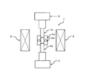
- FIG. 1 shows an embodiment of a forming apparatus in a magnetic field in the method for producing a permanent magnet according to the present embodiment.
- the forming apparatus 1 in a magnetic field has an electromagnet 2 and an upper punch 4a at the upper and lower parts in the drawing. It has a structure having a pressure device 3 having a lower punch 4b and a die 4c having a heating device 4d. It is preferable to reduce the residual magnetic flux density in the temporary molded body by subjecting the temporary molded body to AC demagnetization. During AC demagnetization, it is preferable to raise the temperature of the mold to a predetermined temperature because the residual magnetization becomes smaller.
- the temporary molded body is heated using at least one heating method selected from infrared heating, microwave heating, and high frequency induction heating. Since the mixture can be heated uniformly in a short time, a permanent magnet with high magnetic properties can be obtained.
- infrared heating it is preferable to use infrared rays having a wavelength peak of 0.70 to 3.0 ⁇ m.
- the wavelength peak is shorter than 0.70 ⁇ m, it becomes close to visible light.
- the heating rate is increased, and by shortening the heating time of the mixture, the oxidation of the magnetic powder is suppressed and the deterioration of the magnetic properties can be reduced.
- microwave heating is used as the heating method, the microwave is preferably 0.5 to 50 GHz or less. Generation
- the frequency is preferably 1 to 30 MHz.
- the magnetic powder and the metal binder are selectively and rapidly self-heated to 150 ° C. to 350 ° C., preferably 250 ° C. to 300 ° C., several tens of seconds to several minutes, preferably 1 to 3 minutes. Raise the temperature.
- a high-density permanent magnet can be obtained by uniformly raising the temperature of the entire mixture.
- the temperature can be raised to a predetermined temperature in a short time, the processing time can be shortened and oxidation of the magnetic powder can be suppressed.
- auxiliary heating means such as atmospheric convection heating in some cases, and by using such a heating method, heating with more uniform heating efficiency can be performed. Can do.
- FIG. 2 shows an embodiment of a heating device in the method of manufacturing a permanent magnet according to the present embodiment.
- the heating device 5 includes a metal furnace wall 7a including a heat insulating material or a heat insulating layer.
- a circulating atmosphere outlet 6a and a circulating atmosphere inlet 6b are provided on the upper side in the figure
- a heated product inlet 7b is provided on the right side in the figure
- a heated article discharge port 7c is provided on the left side in the figure.
- the coil 11a and the coil 11b are arranged on the upper and lower surfaces of the temporary molded body 9 to form a structure. By passing an alternating current having a desired frequency through the coils 11a and 11b, the temporary molded body is induction-heated.
- the temporary molded body in the mold cavity may be directly irradiated without using the heating device as shown in FIG.
- the mold and the temporary molded body may be heated at the same time while the temporary molded body is filled in the mold.
- pressurization may be performed while heating in the mold cavity.
- the temporary molded body conveyed on the belt conveyor is heated by at least one method selected from infrared heating, microwave heating, and high-frequency induction heating, and evenly by the heated circulating atmosphere ejected from the circulating atmosphere ejection outlet It will be heated. Since the heating time is as short as about 0.5 to 3 minutes, oxidation of the magnetic powder is suppressed and a permanent magnet having excellent magnetic properties can be obtained.
- the molding process of the present invention is a process in which a temporary molded body heated to a predetermined temperature in the heating process is filled in a mold and pressed to obtain a permanent magnet.
- a high density permanent magnet can be obtained by pressurizing at a high molding pressure of 10 MPa or more.
- a high-density permanent magnet can be obtained by pressing at a molding pressure of preferably 50 MPa or more, more preferably 100 MPa or more, and even more preferably 500 MPa or more. In consideration of the durability of the mold, it is preferable to pressurize at a pressure of 1500 MPa or less. In the molding step, heating is preferable because the density of the permanent magnet is increased and a permanent magnet having high magnetic properties can be obtained.
- the molding temperature is preferably lower than the decomposition temperature 355 ° C. of MnBi, more preferably 250 ° C. to 300 ° C.
- the molding temperature is preferably equal to or higher than the melting point of the metal binder.
- the temporary forming step, heating step, and forming step are preferably performed in an inert gas atmosphere to prevent oxidation of the magnetic powder.
- MnBi anisotropic magnet powder A specified amount of Mn having a purity of 99.9% and Bi having a purity of 99.9% were respectively weighed with an electronic balance, and an ingot was produced by arc melting. The produced ingot was melted using high frequency melting in an Ar atmosphere, and a MnBi ribbon was produced by a liquid quenching method. The obtained ribbon was heated in an Ar atmosphere at 300 ° C. for 12 hours. Then, it grind
- Nd 2 Fe 14 B anisotropic magnet powder An Nd—Fe—B alloy having an atomic fraction of 13% Nd, 12% Co, 1% Ga, 6% B, and the balance Fe is held in hydrogen gas at 700 to 900 ° C. Decomposed into hydride, Fe 2 B, and Fe. Next, the hydrogen pressure was lowered in this temperature region to dissociate hydrogen from the Nd hydride, thereby obtaining a fine magnetic powder of Nd 2 Fe 14 B crystal. The obtained magnetic powder was further mechanically pulverized to obtain anisotropic magnet powder having an average particle size of 150 ⁇ m.
- the metal binder used in the examples and comparative examples was obtained as follows.
- Bi powder and Sn powder Bi powder (purity: 3N, particle size: 30 ⁇ m) and Sn powder (purity: 3N, particle size: 60 ⁇ m) were both made of high-purity chemicals.
- Bi (Bi-Sn alloy powder)
- Sn (product made from high purity chemical, purity: 3N, particle size: 2 to 3 mm)
- the ingot obtained by melting was mechanically pulverized to obtain a 130 ⁇ m alloy powder.
- MnBi and Sm—Fe—N, Nd—Fe—B, and Sm—Co anisotropic magnet powders and metal binders were weighed using an electronic balance at the weight ratios shown in Table 1, respectively, in an Ar atmosphere. Dispersion mixing was performed for 1 hour using a V-type mixer to prepare a mixture.
- the temporary molded body obtained by the above method was heated using the heating apparatus shown in FIG. 2 under the heating conditions shown in Table 3, and the temporary molded body was filled in a mold.
- a 10 mm square cubic permanent magnet sample was prepared by applying the mold temperature, applied magnetic field and molding pressure shown in Table 2. The holding time of the molding pressure was 1 minute.
- (BH) max and Br of the magnetic powder were measured with a vibrating sample magnetometer (VSM) after orientation of the magnetic powder was performed in a magnetic field of 10 kOe, and the magnetic powder was fixed to paraffin.
- a value calculated as the sum of products of (BH) max and volume ratio of each magnetic powder is defined as a theoretical maximum (BH) max.
- (BH) max is 50% or less of the theoretical maximum (BH) max.
- the (BH) max of the sample manufactured in this example was 55% or more of the theoretical maximum (BH) max, it was judged that good magnetic properties were obtained.
- the measured density was calculated by measuring the weight and volume of the obtained sample.
- the calculated density of the mixed powder was calculated from the specific gravity described in Tables 5 and 6 and the weight ratio in Table 1, and the relative density was calculated by dividing the measured density by the calculated density.
- the heat conduction of the magnetic powder is improved and the heating process is uniformly and quickly heated, so that deterioration of magnetic properties due to oxidation can be suppressed.
- Permanent magnets with high magnetic properties were produced.
- the mixture was heated by at least one heating method selected from infrared heating, microwave heating, and high frequency induction heating, so that the temperature of the mixture could be increased uniformly in a short time.
- the magnetic powder could be heated uniformly in a short time, and a permanent magnet excellent in density and magnetic properties could be obtained.
- Example 1 As can be seen from Example 1 and Examples 12 to 14, within the range shown in Table 2, the higher the molding pressure in the molding process, the higher the relative density and the higher the magnetic properties.
- Example 24 to 28 even when the heating method was changed to high frequency induction heating with respect to Example 1, a sample having magnetic characteristics equivalent to those obtained when infrared heating was performed could be obtained. In particular, a sample having relatively high magnetic properties could be obtained in the frequency range of 2 to 10 MHz.
- Example 29 and 30 even when the heating method is changed to a combination of infrared heating and high frequency induction heating, and microwave heating and high frequency induction heating as compared to Example 1, a sample having high magnetic properties can be obtained. did it.
- a sample having a higher (BH) max could be obtained by adding Sm 2 Fe 17 N 3 , Nd 2 Fe 14 B, or Sm 2 Co 17 to MnBi.
- the method for producing a permanent magnet of the present invention is used as a method for producing a permanent magnet for an element of an electric / electronic device.
Landscapes
- Engineering & Computer Science (AREA)
- Manufacturing & Machinery (AREA)
- Power Engineering (AREA)
- Mechanical Engineering (AREA)
- Manufacturing Cores, Coils, And Magnets (AREA)
- Hard Magnetic Materials (AREA)
- Powder Metallurgy (AREA)
Abstract
La présente invention concerne un procédé de fabrication d'un aimant permanent, ledit procédé étant caractérisé en ce qu'il comprend les étapes suivantes : le préformage permettant d'obtenir une préforme par pressurisation d'une poudre magnétique contenant du MnBi dans un champ magnétique ; le chauffage de la préforme à l'aide d'au moins un procédé choisi parmi le chauffage infrarouge, le chauffage par micro-ondes et le chauffage par induction haute fréquence ; le moulage permettant d'obtenir un comprimé par pressurisation de la préforme chauffée. Selon la présente invention, il est possible d'augmenter l'adhérence entre des particules de poudre magnétique par fabrication de la préforme effectuée dans l'étape de préformage par pressurisation de la poudre magnétique contenant du MnBi dans un champ magnétique. La conduction thermique est ainsi améliorée, et il est ainsi possible d'élever rapidement la température à la température souhaitée dans l'étape de chauffage. Par conséquent, il est possible d'obtenir un aimant permanent ayant des caractéristiques magnétiques élevées.
Applications Claiming Priority (2)
| Application Number | Priority Date | Filing Date | Title |
|---|---|---|---|
| JP2016-063493 | 2016-03-28 | ||
| JP2016063493 | 2016-03-28 |
Publications (1)
| Publication Number | Publication Date |
|---|---|
| WO2017170129A1 true WO2017170129A1 (fr) | 2017-10-05 |
Family
ID=59964413
Family Applications (1)
| Application Number | Title | Priority Date | Filing Date |
|---|---|---|---|
| PCT/JP2017/011742 Ceased WO2017170129A1 (fr) | 2016-03-28 | 2017-03-23 | Procédé de fabrication d'un aimant permanent |
Country Status (1)
| Country | Link |
|---|---|
| WO (1) | WO2017170129A1 (fr) |
Cited By (1)
| Publication number | Priority date | Publication date | Assignee | Title |
|---|---|---|---|---|
| CN113539659A (zh) * | 2021-07-16 | 2021-10-22 | 东莞市嘉豪磁性制品有限公司 | 永磁材料的加工工艺 |
Citations (6)
| Publication number | Priority date | Publication date | Assignee | Title |
|---|---|---|---|---|
| JPS56166349A (en) * | 1980-05-22 | 1981-12-21 | Mitsubishi Metal Corp | Manufacture of manganese-bismuth magnet |
| JPH10335124A (ja) * | 1997-05-28 | 1998-12-18 | Daido Steel Co Ltd | 磁性材料粉末およびその製造方法 |
| JP2008255436A (ja) * | 2007-04-06 | 2008-10-23 | Nec Tokin Corp | 永久磁石およびその製造方法 |
| JP2008258463A (ja) * | 2007-04-06 | 2008-10-23 | Nec Tokin Corp | 永久磁石材料とそれを用いた永久磁石およびその製造方法 |
| JP2015063725A (ja) * | 2013-09-25 | 2015-04-09 | 国立大学法人東北大学 | 永久磁石の製造方法 |
| JP2016032116A (ja) * | 2014-07-29 | 2016-03-07 | エルジー エレクトロニクス インコーポレイティド | Mn−Bi系磁性体及びその製造方法、並びにMn−Bi系焼結磁石及びその製造方法 |
-
2017
- 2017-03-23 WO PCT/JP2017/011742 patent/WO2017170129A1/fr not_active Ceased
Patent Citations (6)
| Publication number | Priority date | Publication date | Assignee | Title |
|---|---|---|---|---|
| JPS56166349A (en) * | 1980-05-22 | 1981-12-21 | Mitsubishi Metal Corp | Manufacture of manganese-bismuth magnet |
| JPH10335124A (ja) * | 1997-05-28 | 1998-12-18 | Daido Steel Co Ltd | 磁性材料粉末およびその製造方法 |
| JP2008255436A (ja) * | 2007-04-06 | 2008-10-23 | Nec Tokin Corp | 永久磁石およびその製造方法 |
| JP2008258463A (ja) * | 2007-04-06 | 2008-10-23 | Nec Tokin Corp | 永久磁石材料とそれを用いた永久磁石およびその製造方法 |
| JP2015063725A (ja) * | 2013-09-25 | 2015-04-09 | 国立大学法人東北大学 | 永久磁石の製造方法 |
| JP2016032116A (ja) * | 2014-07-29 | 2016-03-07 | エルジー エレクトロニクス インコーポレイティド | Mn−Bi系磁性体及びその製造方法、並びにMn−Bi系焼結磁石及びその製造方法 |
Non-Patent Citations (2)
| Title |
|---|
| N V RAMA RAO ET AL.: "Anisotropic fully dense MnBi permanent magnet with high energy product and high coercivity at elevated temperatures", JOURNAL OF PHYSICS D: APPLIED PHYSICS, vol. 46, no. 6, 17 January 2013 (2013-01-17), pages 1 - 4, XP020237292, Retrieved from the Internet <URL:doi:10.1088/0022-3727/46/6/062001> * |
| Y. B. YANG ET AL.: "Preparation and magnetic properties of MnBi", JOURNAL OF APPLIED PHYSICS, vol. 111, no. 7, 2012, pages 07E312-1 - 07E312-3, XP012159366, Retrieved from the Internet <URL:doi:10.1063/1.3672086> * |
Cited By (1)
| Publication number | Priority date | Publication date | Assignee | Title |
|---|---|---|---|---|
| CN113539659A (zh) * | 2021-07-16 | 2021-10-22 | 东莞市嘉豪磁性制品有限公司 | 永磁材料的加工工艺 |
Similar Documents
| Publication | Publication Date | Title |
|---|---|---|
| CN101030467B (zh) | 功能梯度稀土永磁体 | |
| CN107871582B (zh) | R-Fe-B烧结磁体 | |
| CN102918611B (zh) | 稀土类永磁体的制造方法和稀土类永磁体 | |
| KR101855530B1 (ko) | 희토류 영구 자석 및 그의 제조 방법 | |
| CN102640238B (zh) | 稀土类各向异性磁铁及其制造方法 | |
| CN1898757B (zh) | 稀土永磁材料的制备方法 | |
| JP6488976B2 (ja) | R−t−b系焼結磁石 | |
| CN100520992C (zh) | 稀土永磁体 | |
| EP3182423B1 (fr) | Aimant néodyme-fer-bore et son procédé de préparation | |
| JP5815655B2 (ja) | R−t−b−m−c系焼結磁石の製造方法、及びその製造装置 | |
| CN107077965A (zh) | R‑t‑b系烧结磁体的制造方法 | |
| KR102219024B1 (ko) | 희토류 영구 자석의 제조방법 | |
| EP2975619A1 (fr) | PROCÉDÉ DE PRODUCTION D'AIMANT FRITTÉ RFeB ET AIMANT FRITTÉ RFeB PRODUIT AINSI | |
| CN108154988B (zh) | R-t-b系永久磁铁 | |
| US11915861B2 (en) | Method for manufacturing rare earth permanent magnet | |
| EP0633582B1 (fr) | Poudre magnetique de terres rares et procede pour sa fabrication | |
| CN106103776B (zh) | 含稀土的合金铸片、其制造方法和烧结磁体 | |
| JP2017069337A (ja) | R−t−b系磁石の製造方法 | |
| JP6691666B2 (ja) | R−t−b系磁石の製造方法 | |
| CN103495733B (zh) | 一种晶界富钕相被替换的烧结钕铁硼永磁材料的制备方法 | |
| JP2019062153A (ja) | R−t−b系焼結磁石の製造方法 | |
| JP2009076631A (ja) | 希土類系メタルボンド磁石の製造方法 | |
| CN107424822A (zh) | 制造具有优异磁特性的稀土永久磁体的方法 | |
| JP6596061B2 (ja) | 希土類永久磁石材料及びその製造方法 | |
| JP6620570B2 (ja) | 金属ボンディッド磁石の製造方法 |
Legal Events
| Date | Code | Title | Description |
|---|---|---|---|
| NENP | Non-entry into the national phase |
Ref country code: DE |
|
| 121 | Ep: the epo has been informed by wipo that ep was designated in this application |
Ref document number: 17774667 Country of ref document: EP Kind code of ref document: A1 |
|
| 122 | Ep: pct application non-entry in european phase |
Ref document number: 17774667 Country of ref document: EP Kind code of ref document: A1 |
|
| NENP | Non-entry into the national phase |
Ref country code: JP |