WO2017170648A1 - Circuit de commande pour outil électrique ayant une fonction de transmission de données de réglage, outil électrique, dispositif de commande et système d'outil électrique - Google Patents
Circuit de commande pour outil électrique ayant une fonction de transmission de données de réglage, outil électrique, dispositif de commande et système d'outil électrique Download PDFInfo
- Publication number
- WO2017170648A1 WO2017170648A1 PCT/JP2017/012825 JP2017012825W WO2017170648A1 WO 2017170648 A1 WO2017170648 A1 WO 2017170648A1 JP 2017012825 W JP2017012825 W JP 2017012825W WO 2017170648 A1 WO2017170648 A1 WO 2017170648A1
- Authority
- WO
- WIPO (PCT)
- Prior art keywords
- control circuit
- setting data
- power tool
- transmission
- information recording
- Prior art date
- Legal status (The legal status is an assumption and is not a legal conclusion. Google has not performed a legal analysis and makes no representation as to the accuracy of the status listed.)
- Ceased
Links
Images


Classifications
-
- B—PERFORMING OPERATIONS; TRANSPORTING
- B25—HAND TOOLS; PORTABLE POWER-DRIVEN TOOLS; MANIPULATORS
- B25B—TOOLS OR BENCH DEVICES NOT OTHERWISE PROVIDED FOR, FOR FASTENING, CONNECTING, DISENGAGING, OR HOLDING
- B25B23/00—Details of, or accessories for, spanners, wrenches, screwdrivers
- B25B23/14—Arrangement of torque limiters or torque indicators in wrenches or screwdrivers
-
- B—PERFORMING OPERATIONS; TRANSPORTING
- B25—HAND TOOLS; PORTABLE POWER-DRIVEN TOOLS; MANIPULATORS
- B25B—TOOLS OR BENCH DEVICES NOT OTHERWISE PROVIDED FOR, FOR FASTENING, CONNECTING, DISENGAGING, OR HOLDING
- B25B21/00—Portable power-driven screw or nut setting or loosening tools; Attachments for drilling apparatus serving the same purpose
-
- B—PERFORMING OPERATIONS; TRANSPORTING
- B25—HAND TOOLS; PORTABLE POWER-DRIVEN TOOLS; MANIPULATORS
- B25B—TOOLS OR BENCH DEVICES NOT OTHERWISE PROVIDED FOR, FOR FASTENING, CONNECTING, DISENGAGING, OR HOLDING
- B25B23/00—Details of, or accessories for, spanners, wrenches, screwdrivers
- B25B23/14—Arrangement of torque limiters or torque indicators in wrenches or screwdrivers
- B25B23/147—Arrangement of torque limiters or torque indicators in wrenches or screwdrivers specially adapted for electrically operated wrenches or screwdrivers
-
- B—PERFORMING OPERATIONS; TRANSPORTING
- B25—HAND TOOLS; PORTABLE POWER-DRIVEN TOOLS; MANIPULATORS
- B25F—COMBINATION OR MULTI-PURPOSE TOOLS NOT OTHERWISE PROVIDED FOR; DETAILS OR COMPONENTS OF PORTABLE POWER-DRIVEN TOOLS NOT PARTICULARLY RELATED TO THE OPERATIONS PERFORMED AND NOT OTHERWISE PROVIDED FOR
- B25F5/00—Details or components of portable power-driven tools not particularly related to the operations performed and not otherwise provided for
-
- G—PHYSICS
- G05—CONTROLLING; REGULATING
- G05B—CONTROL OR REGULATING SYSTEMS IN GENERAL; FUNCTIONAL ELEMENTS OF SUCH SYSTEMS; MONITORING OR TESTING ARRANGEMENTS FOR SUCH SYSTEMS OR ELEMENTS
- G05B19/00—Program-control systems
- G05B19/02—Program-control systems electric
- G05B19/18—Numerical control [NC], i.e. automatically operating machines, in particular machine tools, e.g. in a manufacturing environment, so as to execute positioning, movement or co-ordinated operations by means of program data in numerical form
- G05B19/4093—Numerical control [NC], i.e. automatically operating machines, in particular machine tools, e.g. in a manufacturing environment, so as to execute positioning, movement or co-ordinated operations by means of program data in numerical form characterised by part programming, e.g. entry of geometrical information as taken from a technical drawing, combining this with machining and material information to obtain control information, named part program, for the NC machine
- G05B19/40937—Numerical control [NC], i.e. automatically operating machines, in particular machine tools, e.g. in a manufacturing environment, so as to execute positioning, movement or co-ordinated operations by means of program data in numerical form characterised by part programming, e.g. entry of geometrical information as taken from a technical drawing, combining this with machining and material information to obtain control information, named part program, for the NC machine concerning programming of machining or material parameters, pocket machining
- G05B19/40938—Tool management
-
- G—PHYSICS
- G05—CONTROLLING; REGULATING
- G05B—CONTROL OR REGULATING SYSTEMS IN GENERAL; FUNCTIONAL ELEMENTS OF SUCH SYSTEMS; MONITORING OR TESTING ARRANGEMENTS FOR SUCH SYSTEMS OR ELEMENTS
- G05B19/00—Program-control systems
- G05B19/02—Program-control systems electric
- G05B19/418—Total factory control, i.e. centrally controlling a plurality of machines, e.g. direct or distributed numerical control [DNC], flexible manufacturing systems [FMS], integrated manufacturing systems [IMS] or computer integrated manufacturing [CIM]
-
- G—PHYSICS
- G05—CONTROLLING; REGULATING
- G05B—CONTROL OR REGULATING SYSTEMS IN GENERAL; FUNCTIONAL ELEMENTS OF SUCH SYSTEMS; MONITORING OR TESTING ARRANGEMENTS FOR SUCH SYSTEMS OR ELEMENTS
- G05B19/00—Program-control systems
- G05B19/02—Program-control systems electric
- G05B19/42—Recording and playback systems, i.e. in which the program is recorded from a cycle of operations, e.g. the cycle of operations being manually controlled, after which this record is played back on the same machine
-
- Y—GENERAL TAGGING OF NEW TECHNOLOGICAL DEVELOPMENTS; GENERAL TAGGING OF CROSS-SECTIONAL TECHNOLOGIES SPANNING OVER SEVERAL SECTIONS OF THE IPC; TECHNICAL SUBJECTS COVERED BY FORMER USPC CROSS-REFERENCE ART COLLECTIONS [XRACs] AND DIGESTS
- Y02—TECHNOLOGIES OR APPLICATIONS FOR MITIGATION OR ADAPTATION AGAINST CLIMATE CHANGE
- Y02P—CLIMATE CHANGE MITIGATION TECHNOLOGIES IN THE PRODUCTION OR PROCESSING OF GOODS
- Y02P90/00—Enabling technologies with a potential contribution to greenhouse gas [GHG] emissions mitigation
- Y02P90/02—Total factory control, e.g. smart factories, flexible manufacturing systems [FMS] or integrated manufacturing systems [IMS]
Definitions
- the present invention relates to a control circuit for controlling an electric tool main body including an electric motor, an electric tool and a control device including the control circuit, and an electric tool system including a plurality of control circuits.
- the present invention relates to a control circuit, a power tool, a control device, and a power tool system having a function of transmitting setting data of a power tool body.
- the power tool is set to the original power tool. It is necessary to perform a set of new electric tool with reference to the setting data that has been recorded on or in advance somewhere to refer directly to the configuration data are.
- the number of setting items is gradually increasing as the power tools become more functional, and the setting items are further increased in power tools that control multiple power tool bodies with a single control device. Become. It is complicated to input the setting data of such a huge number of setting items one by one, and input errors are likely to occur.
- the present invention provides a control circuit for a power tool that can quickly set setting data set for a power tool with another power tool, a power tool and a control device including the control circuit, and
- An object of the present invention is to provide a power tool system including a plurality of control circuits connected to each other in communication.
- control circuit Since the control circuit has a function of transmitting the setting data of the power tool main body to other control circuits, it is not necessary for the operator to input the setting data one by one in the control circuit on the receiving side. Further, if the control circuit directly transmits to the control circuit for controlling another power tool body, it is not necessary to use another device such as a remote controller for inputting the setting data.
- the setting data can be set more quickly and easily. In addition, it is possible to prevent an artificial input error of the setting data. Even when setting via a remote control, etc., a control circuit for transmitting the setting data currently set in the control circuit to the remote control, etc., and controlling the other power tool body with the remote control etc.
- the “other control circuit” in the present application includes not only a control circuit for controlling the power tool body but also a device for setting and managing the power tool, such as a computer or a remote controller. .
- Transmission data selection means for selecting setting data to be transmitted by the communication means from the setting data recorded in the information recording means,
- the communication unit can transmit only the setting data selected by the transmission data selection unit.
- the amount of data to be transmitted can be reduced by selecting the setting data to be transmitted. It is also possible to set only some of the setting items in the control circuit on the receiving side.
- the communication unit may further include a reception function for receiving setting data transmitted from another control circuit.
- the setting data recorded in the information recording means can be easily matched with the setting data in other control circuits.
- the present invention also provides A power tool body; The above-described control circuit built in the power tool body; An electric tool provided with
- the present invention is a control device having the above-described control circuit, and is capable of communication connection with a power tool body that is separate from the control device, and the communication-connected power tool body is controlled by the control circuit.
- a control device adapted to do so.
- a plurality of power tool bodies can be communicably connected, and a plurality of power tool bodies connected by communication are controlled.
- the information recording means of the control circuit records each setting data of the plurality of power tool bodies connected by communication, and the communication means can transmit each setting data of the plurality of power tool bodies to other control circuits. It can be.
- the setting data is required for each power tool main body, so the amount increases in proportion to the number of power tool main bodies.
- the said control apparatus since it is possible to transmit each setting data with respect to a several electric tool main body to another control circuit, many setting data can be set to another control circuit quickly and reliably. It becomes possible.
- the present invention also provides A control device as described above; An electric power tool body connected to the control device by communication; An electric tool comprising:
- the present invention provides A first control circuit for controlling the first power tool main body, the first information recording means for recording the setting data of the first power tool main body, and the setting data recorded in the first information recording means
- a first control circuit comprising a first communication means having a transmission function for transmitting
- a second control circuit for controlling the second power tool main body, the second information recording means for recording setting data of the second power tool main body, and the first information recording for the first control circuit
- Second communication means having a transmission request function for transmitting a transmission request signal for requesting transmission of setting data recorded in the means, and a receiving function for receiving setting data transmitted from the first control circuit
- a second control circuit comprising:
- the first communication means further has a reception function of receiving the transmission request signal,
- the first control circuit transmits the setting data recorded in the first information recording means to the second control circuit when receiving the transmission request signal, and the second control circuit transmits the transmission data
- an electric tool system configured to receive the received setting data and record the received setting data in the second information recording means.
- the second control circuit further comprises reception data selection means for selecting setting data to be recorded in the second information recording means from the received setting data, Only the setting data selected by the received data selection means from the received setting data can be recorded in the second information recording means.
- reception data selection means only necessary setting data can be recorded in the information recording means, and only necessary setting items can be set to the same setting as the control circuit on the transmission side.
- the transmission request signal includes transmission data designation information for designating setting data for requesting transmission to the first control circuit;
- the first control circuit selects setting data to be transmitted based on the transmission data designation information, and the first communication means transmits only the selected setting data. 2 can be transmitted to the control circuit.
- Such a configuration makes it possible to reduce the amount of data to be communicated.
- FIG. 1 is an external view of an electric driver according to a first embodiment of the present invention. It is a functional block diagram of the electric driver of FIG. It is a 1st flowchart which shows the operation
- FIG. 6 is a second flowchart showing an operation at the time of transmission / reception of setting data in the electric driver of FIG. 1. It is an external view of the electric driver which concerns on the 2nd Embodiment of this invention.
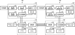
- an electric driver (electric tool) 100 includes an electric motor 112 built therein and a bit holder 114 that is rotationally driven by the electric motor 112.
- a driver main body (electric tool main body) 110 and a motor drive circuit 120 for rotationally driving the bit holder 114 are provided.
- the bit holder 114 is removably attached with a driver bit 116 appropriately selected according to the target screw.
- the electric driver main body 110 is provided with an input interface 130 having a display unit 132 and an input button 134, and a power cord 118.
- the electric driver further includes a control circuit 140 for controlling the electric driver main body 110 in the electric driver main body 110.
- the motor drive circuit 120 of the electric driver main body 110 includes an electric motor 112 for rotating the driver bit 116, a motor control unit 122 for driving the electric motor 112, a hall sensor 124 for detecting the rotation of the electric motor 112, and A central control unit 126 for controlling the motor control unit 122 and the hall sensor 124 is provided.
- an AC / DC conversion unit 128 that converts an alternating current supplied from the power cord 118 into a direct current for the motor control unit 122
- an AC / DC conversion unit 129 that converts the alternating current to a direct current for the central control unit 126 are provided. .
- the control circuit 140 for controlling the electric driver main body 110 corresponds to various setting items such as the rotation speed and rotation time of the electric motor 112, the screw tightening torque, and the criteria for determining normal screw tightening in the electric driver main body 110.
- the memory (information recording means) 142 for recording each setting data, the communication unit (communication means) 144 for performing wireless communication with other electric drivers, the memory 142 and the communication unit 144 are controlled, and the electric motor
- a central control unit 146 that controls the motor drive circuit 120 of the driver main body 110 based on setting data recorded in the memory 142.
- the central control unit 146 is connected to the input interface 130, and changes setting data, transmits / receives setting data, and the like based on an input from the input interface 130.
- the control circuit 140 further has a buzzer 148 so as to notify the operator of the completion or error of a predetermined operation by sound.
- Another electric driver 100 ′ connected to the electric driver 100 for communication is the same as the electric driver 100, and corresponding components are denoted by similar reference numerals.
- These electric drivers 100 and 100 ′ constitute an electric driver system (electric tool system) that is connected to each other by communication units 144 and 144 ′.
- the electric driver 100 on the transmission side is turned on to start control (S100), and the electric driver 100 is shifted to the transmission mode by operating the input interface 130 (S112).
- the transmission mode is entered, it is temporarily impossible to change the setting data or drive the electric motor 112.
- the model of the receiving-side electric driver 100 ′ to be a transmission partner is selected (S 114). Since the communication protocol that can be received may differ depending on the model, the model of the receiving-side electric driver 100 ′ is selected in advance, and data communication is performed using a communication protocol that matches the receiving-side electric driver 100 ′. Keep it. Note that the number of electric driver models will increase each time a new electric driver is developed. In such a case, the selectable electric driver model set in the control circuit 140 is updated as needed.
- the setting data is read from the memory (first information recording means) 142 of the control circuit (first control circuit) 140 of the transmission-side electric driver main body (first electric tool main body) 110 (S116).
- the transmission-side control circuit 140 has a function (transmission data selection means) for selecting setting data to be transmitted from the read setting data in response to an input from the input interface 130, and only a part of the setting data is selected. In the case of transmission, the setting data to be transmitted is selected here (S118).
- the receiving-side electric driver 100 ′ is a different model from the transmitting-side electric driver 100
- setting data that cannot be set in the receiving-side electric driver 100 ′ may be included in the transmitting-side setting data.
- the transmission-side control circuit 140 encodes the setting data so as to correspond to the model of the receiving-side electric driver 100 ′ that is the transmission partner (S120), and the setting data is transmitted to the communication unit. (First communication means) It transmits by 144 (S122).
- the electric driver 100 ′ on the reception side before the transmission of the setting data from the control circuit 140 on the transmission side is started (S122), the power is turned on and the control is started (S150), and the input interface 130 ′ is operated. For example, the electric driver 100 ′ is shifted to the reception mode (S152). When the mode is shifted to the reception mode, it is temporarily impossible to change the setting data or drive the electric motor 112 '.
- the reception-side driver receives the control circuit (second electric tool main body) built in the electric driver main body (second electric tool main body). (2 control circuit)
- the setting data transmitted by the communication unit (second communication means) 144 ′ of 140 ′ is received (S154).
- the receiving-side control circuit 140 ' returns the received setting data from the communication unit 144' to the transmitting-side control circuit 140 (S158).
- the transmission-side control circuit 140 receives the setting data returned from the reception-side control circuit 140 '(S126).
- the control circuit 140 on the transmission side compares the transmitted setting data with the returned setting data to determine whether the setting data has been properly transmitted and received (S128). S130). That is, if there is no difference between the transmitted setting data and the returned setting data, the receiving-side control circuit 140 'determines that the setting data has been properly received. As a result of this determination, when it is determined that communication of appropriate setting data has been performed, the control circuit 140 on the transmission side transmits an OK signal (S132) and uses a buzzer 148 to generate a sound indicating that.
- the receiving-side control circuit 140 receives the OK signal or NG signal transmitted from the transmitting-side control circuit 140 after the return of the setting data is completed (S160) (S162).
- the OK signal is received, a sound indicating that is sounded by the buzzer 148 '(S164), and the received setting data is decoded (S166).
- the receiving-side control circuit 140 ′ has a function (received data selecting means) for selecting setting data to be written in the memory (second information recording means) 142 ′ from the setting data received by the input from the input interface 130 ′. In the case where only a part of the received setting data is written in the memory 142 ′, the setting data to be written is selected here (S168).
- the selected setting data is written into the memory 142 ′ (S 170), and when the writing is completed, a sound indicating that is made by the buzzer 148 ′ (S 174). On the other hand, if an NG signal is received, a sound indicating that is sounded by the buzzer 148 '(S172).
- the setting data written in the memory 142 ′ becomes valid, and the electric driver main body can be driven and controlled by the same settings as those in the control circuit 140 on the transmission side.
- both the transmission-side electric driver and the reception-side electric driver are turned on to start control (S200, S250), and the reception-side control circuit 140 ′ is shifted to the reception mode (S252). .
- the communication unit 144 ′ of the reception-side control circuit 140 ′ has a function of transmitting a transmission request signal for requesting the transmission-side control circuit 140 to transmit setting data (transmission request function). Yes.
- the transmission request signal is transmitted together with the device information of the electric driver 100 'on the receiving side (S253).
- the transmission-side control circuit 140 receives the transmission request signal and device information from the reception-side control circuit 140 '(S211), the transmission-side control circuit 140 automatically shifts to the transmission mode (S212).
- the model of the electric driver 100 'on the receiving side is determined based on the received device information (S214).
- transmission data designation information that designates setting data for requesting transmission to the transmission-side control circuit 140 can be included in the transmission request signal.
- the transmission-side control circuit 140 selects the designated transmission data from the setting data recorded in the memory 142 based on the transmission data designation information Then, only the selected transmission data is transmitted to the receiving-side control circuit 140 ′ by the communication unit 144. Steps S216 to S240 in the control circuit 140 on the transmission side shown in FIG. 4 and steps S254 to S276 in the control circuit 140 ′ on the reception side shown in FIG.
- the electric driver 100 on the transmission side is searched.
- a plurality of electric drivers 100 are searched, one electric driver 100 is selected from the electric drivers 100 and the electric driver 100 is selected. It is also possible to transmit a transmission request signal only for.
- the electric driver 200 includes an electric driver main body 210 and a control device 250 that is separate from the electric driver main body 210.
- the control device 250 includes an input interface 230 having a display unit 232 and an input button 234, and a control circuit 140 (FIG. 2) for controlling the electric driver main body 210 is built therein.
- the configuration and function of the control circuit 140 in the electric driver 200 are the same as those in the electric driver 100 according to the first embodiment.
- the control device 250 and the electric driver main body 210 are communicatively connected by a cable 252. In FIG.
- only one electric driver main body 210 is connected to the control device 250, but the control device 250 can communicate with a plurality of electric driver main bodies 210, and a plurality of electric driver main bodies connected by communication It is also possible to control 210 simultaneously. In that case, each setting data for the plurality of electric driver main bodies 210 is recorded in the memory 142 in the control circuit 140 in the control device 250. The control device 250 can collectively transmit the setting data for the plurality of electric driver main bodies 210 to other control devices. Further, for the electric driver 100 having the control circuit 140 built in the electric driver main body 110 as shown in FIG. 1, setting data for one electric driver main body 210 among the plurality of electric driver main bodies 210 is selected. Thus, it is possible to transmit only the selected setting data.
- the control circuit according to the present invention has a function of transmitting the setting data of the power tool main body to the control circuit in another power tool.
- the setting data can be transmitted directly from the control circuit, it is not necessary to use another device such as a remote controller for inputting the setting data. Therefore, in the control circuit, it is possible to quickly and easily set the power tool, and it is also possible to prevent an artificial input error of the setting data.
- the electric tool according to the present invention has been described using the electric drivers 100 and 200 as an example, but other electric tools such as an electric drill may be used.
- the communication between the control circuits 140 and 140 ′ is performed wirelessly.
- the communication units 144 and 144 ′ of the control circuits 140 and 140 ′ are connected to each other with a cable to set data or the like. May be transmitted / received.
- the communication between the control circuits 140 and 140 ′ is not necessarily a one-to-one communication.
- the setting data may be simultaneously transmitted from one control circuit 140 to a plurality of control circuits.
- the setting data can be transmitted from the control circuit 140 to a computer or a remote controller for managing and setting the setting data of the power tool.
- the communication unit 144 of the control circuit 140 can receive not only setting data transmitted from another control circuit 140 but also setting data transmitted from other control circuits including other devices such as a conventional remote controller. Also good.
Landscapes
- Engineering & Computer Science (AREA)
- Physics & Mathematics (AREA)
- Mechanical Engineering (AREA)
- General Physics & Mathematics (AREA)
- Manufacturing & Machinery (AREA)
- Automation & Control Theory (AREA)
- Quality & Reliability (AREA)
- General Engineering & Computer Science (AREA)
- Geometry (AREA)
- Human Computer Interaction (AREA)
- Portable Power Tools In General (AREA)
- Control Of Electric Motors In General (AREA)
- Arrangements For Transmission Of Measured Signals (AREA)
- Details Of Spanners, Wrenches, And Screw Drivers And Accessories (AREA)
Abstract
Priority Applications (4)
| Application Number | Priority Date | Filing Date | Title |
|---|---|---|---|
| JP2018508126A JP6576543B2 (ja) | 2016-03-29 | 2017-03-29 | 設定データ送信機能を有する電動工具の制御回路、電動工具、制御装置、および電動工具システム |
| CN201780021659.7A CN108883527B (zh) | 2016-03-29 | 2017-03-29 | 具有设定数据发送功能的电动工具的控制电路、电动工具、控制装置以及电动工具系统 |
| DE112017001750.5T DE112017001750B4 (de) | 2016-03-29 | 2017-03-29 | Steuerschaltung eines Elektroantriebswerkzeugs mit Einstelldatenübertragungsfunktion, Elektroantriebswerkzeug, Steuereinheit und Elektroantriebswerkzeugsystem |
| KR1020187028443A KR102180654B1 (ko) | 2016-03-29 | 2017-03-29 | 설정 데이터 송신 기능을 갖는 전동 공구의 제어 회로, 전동 공구, 제어 장치, 및 전동 공구 시스템 |
Applications Claiming Priority (2)
| Application Number | Priority Date | Filing Date | Title |
|---|---|---|---|
| JP2016-064922 | 2016-03-29 | ||
| JP2016064922 | 2016-03-29 |
Publications (1)
| Publication Number | Publication Date |
|---|---|
| WO2017170648A1 true WO2017170648A1 (fr) | 2017-10-05 |
Family
ID=59965890
Family Applications (1)
| Application Number | Title | Priority Date | Filing Date |
|---|---|---|---|
| PCT/JP2017/012825 Ceased WO2017170648A1 (fr) | 2016-03-29 | 2017-03-29 | Circuit de commande pour outil électrique ayant une fonction de transmission de données de réglage, outil électrique, dispositif de commande et système d'outil électrique |
Country Status (6)
| Country | Link |
|---|---|
| JP (1) | JP6576543B2 (fr) |
| KR (1) | KR102180654B1 (fr) |
| CN (1) | CN108883527B (fr) |
| DE (1) | DE112017001750B4 (fr) |
| TW (1) | TWI622466B (fr) |
| WO (1) | WO2017170648A1 (fr) |
Cited By (4)
| Publication number | Priority date | Publication date | Assignee | Title |
|---|---|---|---|---|
| WO2019124009A1 (fr) | 2017-12-18 | 2019-06-27 | 日東工器株式会社 | Outil, et circuit de commande et procédé de commande pour outil |
| TWI690396B (zh) * | 2017-12-18 | 2020-04-11 | 日商日東工器股份有限公司 | 電動工具以及電動工具的控制電路及控制方法 |
| WO2021060015A1 (fr) * | 2019-09-27 | 2021-04-01 | 日東工器株式会社 | Circuit de commande destiné à un outil électrique, dispositif de commande et outil électrique |
| JPWO2022070762A1 (fr) * | 2020-09-30 | 2022-04-07 |
Families Citing this family (4)
| Publication number | Priority date | Publication date | Assignee | Title |
|---|---|---|---|---|
| US10747205B2 (en) | 2018-05-18 | 2020-08-18 | Ingersoll-Rand Industrial U.S., Inc. | Electronic tool and method for copying a plurality of settings from a mechanical tool to another mechanical tool |
| TWI676348B (zh) * | 2018-05-25 | 2019-11-01 | 車王電子股份有限公司 | 電動工具 |
| CN113400237A (zh) * | 2021-07-19 | 2021-09-17 | 南昌博格技术有限公司 | 一种可防错的电动螺丝刀、控制器和计算机拧紧系统 |
| JP7810611B2 (ja) * | 2022-06-10 | 2026-02-03 | パナソニックホールディングス株式会社 | 電動工具及び電動工具システム |
Citations (6)
| Publication number | Priority date | Publication date | Assignee | Title |
|---|---|---|---|---|
| JPH07308865A (ja) * | 1994-05-13 | 1995-11-28 | Nissan Motor Co Ltd | インパクト式ねじ締め装置 |
| JP2008213086A (ja) * | 2007-03-02 | 2008-09-18 | Matsushita Electric Works Ltd | 電動工具制御システム |
| JP2012240165A (ja) * | 2011-05-20 | 2012-12-10 | Hitachi Koki Co Ltd | 電動工具 |
| JP2014021538A (ja) * | 2012-07-12 | 2014-02-03 | Hitachi Koki Co Ltd | 動力工具の作業状況管理システム |
| WO2015061370A1 (fr) * | 2013-10-21 | 2015-04-30 | Milwaukee Electric Tool Corporation | Adaptateur pour dispositifs d'outil électrique |
| JP2016013588A (ja) * | 2014-07-01 | 2016-01-28 | パナソニックIpマネジメント株式会社 | 電動工具システム |
Family Cites Families (19)
| Publication number | Priority date | Publication date | Assignee | Title |
|---|---|---|---|---|
| US20030105599A1 (en) * | 2001-11-30 | 2003-06-05 | Fisher Craig Brett | System for ensuring proper completion of tasks |
| JP4329369B2 (ja) * | 2003-03-20 | 2009-09-09 | パナソニック電工株式会社 | 電動工具の使用支援方法及びその装置 |
| EP1559511A3 (fr) * | 2004-01-30 | 2010-05-05 | BLACK & DECKER INC. | Système et méthode pour communiquer des données concernant un outil à courant continu sans fil par le biais de sa station de rechargement |
| TWI235900B (en) * | 2004-03-24 | 2005-07-11 | Charming Systems Corp | System and method for managing equipments |
| TWM322861U (en) * | 2007-01-09 | 2007-12-01 | Eclatorq Technology Co Ltd | Digital torsional wrench |
| US20110182278A1 (en) * | 2008-10-03 | 2011-07-28 | Leonard Tsai | Eui based remote database for dynamic device control |
| JP5537055B2 (ja) * | 2009-03-24 | 2014-07-02 | 株式会社マキタ | 電動工具 |
| JP5431006B2 (ja) | 2009-04-16 | 2014-03-05 | Tone株式会社 | ワイヤレス・データ送受信システム |
| TWM378080U (en) * | 2009-09-21 | 2010-04-11 | Legend Lifestyle Products Corp | Torque sensing and displaying device for tool |
| TWM381484U (en) * | 2009-11-13 | 2010-06-01 | Legend Lifestyle Products Corp | Torque wrench having wireless transmission function |
| TWM392713U (en) * | 2010-07-12 | 2010-11-21 | Legend Lifestyle Products Corp | Wireless torque wrench with angle correction feature |
| TWM394880U (en) * | 2010-07-19 | 2010-12-21 | Legend Lifestyle Products Corp | Multi-functional torque sensor device |
| TWM395554U (en) * | 2010-08-27 | 2011-01-01 | Legend Lifestyle Products Corp | Torque wrench |
| US20140069672A1 (en) * | 2011-05-20 | 2014-03-13 | Hitachi Koki Co., Ltd. | Power Tool |
| DE102012221997A1 (de) | 2012-05-25 | 2013-11-28 | Robert Bosch Gmbh | Elektrowerkzeug |
| DE102012223007A1 (de) * | 2012-12-13 | 2014-06-18 | Hilti Aktiengesellschaft | Handgeführtes oder halbstationäres Werkzeuggerät und Verfahren zum Betreiben eines derartigen Werkzeuggeräts |
| US9466198B2 (en) * | 2013-02-22 | 2016-10-11 | Milwaukee Electric Tool Corporation | Wireless tracking of power tools and related devices |
| TW201533552A (zh) * | 2014-02-27 | 2015-09-01 | Hope Ind Corp | 資料記錄之監控整合系統 |
| JP2015221494A (ja) * | 2015-09-08 | 2015-12-10 | 日東工器株式会社 | 螺合部材締め付け工具及びカウント装置 |
-
2017
- 2017-03-29 WO PCT/JP2017/012825 patent/WO2017170648A1/fr not_active Ceased
- 2017-03-29 KR KR1020187028443A patent/KR102180654B1/ko active Active
- 2017-03-29 DE DE112017001750.5T patent/DE112017001750B4/de active Active
- 2017-03-29 JP JP2018508126A patent/JP6576543B2/ja active Active
- 2017-03-29 CN CN201780021659.7A patent/CN108883527B/zh active Active
- 2017-03-29 TW TW106110568A patent/TWI622466B/zh active
Patent Citations (6)
| Publication number | Priority date | Publication date | Assignee | Title |
|---|---|---|---|---|
| JPH07308865A (ja) * | 1994-05-13 | 1995-11-28 | Nissan Motor Co Ltd | インパクト式ねじ締め装置 |
| JP2008213086A (ja) * | 2007-03-02 | 2008-09-18 | Matsushita Electric Works Ltd | 電動工具制御システム |
| JP2012240165A (ja) * | 2011-05-20 | 2012-12-10 | Hitachi Koki Co Ltd | 電動工具 |
| JP2014021538A (ja) * | 2012-07-12 | 2014-02-03 | Hitachi Koki Co Ltd | 動力工具の作業状況管理システム |
| WO2015061370A1 (fr) * | 2013-10-21 | 2015-04-30 | Milwaukee Electric Tool Corporation | Adaptateur pour dispositifs d'outil électrique |
| JP2016013588A (ja) * | 2014-07-01 | 2016-01-28 | パナソニックIpマネジメント株式会社 | 電動工具システム |
Cited By (9)
| Publication number | Priority date | Publication date | Assignee | Title |
|---|---|---|---|---|
| WO2019124009A1 (fr) | 2017-12-18 | 2019-06-27 | 日東工器株式会社 | Outil, et circuit de commande et procédé de commande pour outil |
| TWI690396B (zh) * | 2017-12-18 | 2020-04-11 | 日商日東工器股份有限公司 | 電動工具以及電動工具的控制電路及控制方法 |
| KR20200089710A (ko) | 2017-12-18 | 2020-07-27 | 니토 코키 가부시키가이샤 | 공구 그리고 공구의 제어 회로 및 제어 방법 |
| US11701766B2 (en) | 2017-12-18 | 2023-07-18 | Nitto Kohki Co., Ltd. | Tool, and control circuit and control method therefor |
| WO2021060015A1 (fr) * | 2019-09-27 | 2021-04-01 | 日東工器株式会社 | Circuit de commande destiné à un outil électrique, dispositif de commande et outil électrique |
| JPWO2021060015A1 (fr) * | 2019-09-27 | 2021-04-01 | ||
| JP7196329B2 (ja) | 2019-09-27 | 2022-12-26 | 日東工器株式会社 | 電動工具の制御回路、制御装置、および電動工具 |
| JPWO2022070762A1 (fr) * | 2020-09-30 | 2022-04-07 | ||
| JP7517445B2 (ja) | 2020-09-30 | 2024-07-17 | 工機ホールディングス株式会社 | 作業機システム |
Also Published As
| Publication number | Publication date |
|---|---|
| DE112017001750B4 (de) | 2022-11-03 |
| JP6576543B2 (ja) | 2019-09-18 |
| TWI622466B (zh) | 2018-05-01 |
| TW201808552A (zh) | 2018-03-16 |
| KR20180123069A (ko) | 2018-11-14 |
| JPWO2017170648A1 (ja) | 2018-06-28 |
| CN108883527B (zh) | 2021-09-03 |
| KR102180654B1 (ko) | 2020-11-19 |
| CN108883527A (zh) | 2018-11-23 |
| DE112017001750T5 (de) | 2019-01-03 |
Similar Documents
| Publication | Publication Date | Title |
|---|---|---|
| JP6576543B2 (ja) | 設定データ送信機能を有する電動工具の制御回路、電動工具、制御装置、および電動工具システム | |
| CN204833259U (zh) | 电动工具及电动工具系统 | |
| CN105826966A (zh) | 将无线充电装置与人机界面(hmi)集成 | |
| JP7021075B2 (ja) | パワーレンチと外部操作部とを備えた工具システム | |
| US10559967B2 (en) | Switchable interface for power tools | |
| US10096188B2 (en) | Fixed location based trainable transceiver for the control of remote devices systems and methods | |
| CN103886247A (zh) | 具有中央授权管理单元和工具装置的系统 | |
| CN102821902A (zh) | 用于将无线控制器绑定到焊接电源的方法和系统 | |
| JPWO2017043535A1 (ja) | 螺合部材締め付け工具及びカウント装置 | |
| JP2019042860A (ja) | 工具システム、画像処理方法、及びプログラム | |
| CN108472801A (zh) | 具有档位切换单元的手持式工具机 | |
| US12070845B2 (en) | Electronic power tool and electric power tool system | |
| CN114342206A (zh) | 适配器 | |
| CN207309878U (zh) | 一种可自动识别钻头的电动装置、钻头及电动工具 | |
| CN108698138B (zh) | 一种可自动识别钻头的电动装置、钻头及电动工具 | |
| CN109746914B (zh) | 构建机器人的方法、机器人控制设备、系统及存储介质 | |
| CN108768693B (zh) | 多网络端口中共享端口的识别方法、存储介质及服务器 | |
| US20240123590A1 (en) | Adaptable Motor Control of Modular Power Tool | |
| TW201817553A (zh) | 電動工具及其操控方法 | |
| US12307883B2 (en) | Electric tool system, management system, management method, and non-transitory storage medium | |
| JP2009126323A (ja) | 車両用故障診断装置 | |
| JP4760738B2 (ja) | 電動工具制御システム | |
| CN107520818A (zh) | 用于辅助便携式工具机的操作者的方法 | |
| JP7196329B2 (ja) | 電動工具の制御回路、制御装置、および電動工具 | |
| JP2021058946A (ja) | 電動工具の制御回路、電動工具、及び電動工具システム |
Legal Events
| Date | Code | Title | Description |
|---|---|---|---|
| ENP | Entry into the national phase |
Ref document number: 2018508126 Country of ref document: JP Kind code of ref document: A |
|
| ENP | Entry into the national phase |
Ref document number: 20187028443 Country of ref document: KR Kind code of ref document: A |
|
| 121 | Ep: the epo has been informed by wipo that ep was designated in this application |
Ref document number: 17775185 Country of ref document: EP Kind code of ref document: A1 |
|
| 122 | Ep: pct application non-entry in european phase |
Ref document number: 17775185 Country of ref document: EP Kind code of ref document: A1 |