WO2017170850A1 - 5-ブロモメチル-1-ベンゾチオフェンの製造方法 - Google Patents
5-ブロモメチル-1-ベンゾチオフェンの製造方法 Download PDFInfo
- Publication number
- WO2017170850A1 WO2017170850A1 PCT/JP2017/013206 JP2017013206W WO2017170850A1 WO 2017170850 A1 WO2017170850 A1 WO 2017170850A1 JP 2017013206 W JP2017013206 W JP 2017013206W WO 2017170850 A1 WO2017170850 A1 WO 2017170850A1
- Authority
- WO
- WIPO (PCT)
- Prior art keywords
- compound
- reaction
- benzothiophene
- solvent
- brominating agent
- Prior art date
- Legal status (The legal status is an assumption and is not a legal conclusion. Google has not performed a legal analysis and makes no representation as to the accuracy of the status listed.)
- Ceased
Links
- HOVPXJOSTYXDCM-UHFFFAOYSA-N OC(Cc1ccc2[s]ccc2c1)=O Chemical compound OC(Cc1ccc2[s]ccc2c1)=O HOVPXJOSTYXDCM-UHFFFAOYSA-N 0.000 description 1
- HQNACSFBDBYLJP-UHFFFAOYSA-N OC1CN(CCCOCCc2ccc3[s]ccc3c2)C1 Chemical compound OC1CN(CCCOCCc2ccc3[s]ccc3c2)C1 HQNACSFBDBYLJP-UHFFFAOYSA-N 0.000 description 1
Images
Classifications
-
- C—CHEMISTRY; METALLURGY
- C07—ORGANIC CHEMISTRY
- C07D—HETEROCYCLIC COMPOUNDS
- C07D333/00—Heterocyclic compounds containing five-membered rings having one sulfur atom as the only ring hetero atom
- C07D333/50—Heterocyclic compounds containing five-membered rings having one sulfur atom as the only ring hetero atom condensed with carbocyclic rings or ring systems
- C07D333/52—Benzo[b]thiophenes; Hydrogenated benzo[b]thiophenes
- C07D333/54—Benzo[b]thiophenes; Hydrogenated benzo[b]thiophenes with only hydrogen atoms, hydrocarbon or substituted hydrocarbon radicals, directly attached to carbon atoms of the hetero ring
-
- B—PERFORMING OPERATIONS; TRANSPORTING
- B01—PHYSICAL OR CHEMICAL PROCESSES OR APPARATUS IN GENERAL
- B01J—CHEMICAL OR PHYSICAL PROCESSES, e.g. CATALYSIS OR COLLOID CHEMISTRY; THEIR RELEVANT APPARATUS
- B01J19/00—Chemical, physical or physico-chemical processes in general; Their relevant apparatus
- B01J19/08—Processes employing the direct application of electric or wave energy, or particle radiation; Apparatus therefor
- B01J19/12—Processes employing the direct application of electric or wave energy, or particle radiation; Apparatus therefor employing electromagnetic waves
- B01J19/122—Incoherent waves
- B01J19/123—Ultraviolet light
-
- B—PERFORMING OPERATIONS; TRANSPORTING
- B01—PHYSICAL OR CHEMICAL PROCESSES OR APPARATUS IN GENERAL
- B01J—CHEMICAL OR PHYSICAL PROCESSES, e.g. CATALYSIS OR COLLOID CHEMISTRY; THEIR RELEVANT APPARATUS
- B01J19/00—Chemical, physical or physico-chemical processes in general; Their relevant apparatus
- B01J19/08—Processes employing the direct application of electric or wave energy, or particle radiation; Apparatus therefor
- B01J19/12—Processes employing the direct application of electric or wave energy, or particle radiation; Apparatus therefor employing electromagnetic waves
- B01J19/122—Incoherent waves
- B01J19/127—Sunlight; Visible light
-
- B—PERFORMING OPERATIONS; TRANSPORTING
- B01—PHYSICAL OR CHEMICAL PROCESSES OR APPARATUS IN GENERAL
- B01J—CHEMICAL OR PHYSICAL PROCESSES, e.g. CATALYSIS OR COLLOID CHEMISTRY; THEIR RELEVANT APPARATUS
- B01J2219/00—Chemical, physical or physico-chemical processes in general; Their relevant apparatus
- B01J2219/08—Processes employing the direct application of electric or wave energy, or particle radiation; Apparatus therefor
- B01J2219/0873—Materials to be treated
- B01J2219/0877—Liquid
-
- B—PERFORMING OPERATIONS; TRANSPORTING
- B01—PHYSICAL OR CHEMICAL PROCESSES OR APPARATUS IN GENERAL
- B01J—CHEMICAL OR PHYSICAL PROCESSES, e.g. CATALYSIS OR COLLOID CHEMISTRY; THEIR RELEVANT APPARATUS
- B01J2219/00—Chemical, physical or physico-chemical processes in general; Their relevant apparatus
- B01J2219/08—Processes employing the direct application of electric or wave energy, or particle radiation; Apparatus therefor
- B01J2219/12—Processes employing electromagnetic waves
- B01J2219/1203—Incoherent waves
Definitions
- the present invention relates to a method for producing 5-bromomethyl-1-benzothiophene, which is useful as a pharmaceutical production intermediate.
- 1- (3- (2- (1-benzothiophen-5-yl) ethoxy) propyl) azetidin-3-ol is a useful compound as a therapeutic agent for diseases of the central and peripheral nerves.
- This compound is produced, for example, from 1-benzothiophene-5-acetic acid (Patent Document 1).
- 1-benzothiophene-5-acetic acid is produced from, for example, 5-bromomethyl-1-benzothiophene (hereinafter sometimes referred to as “compound A”) (Non-patent Document 1).
- Compound A is a useful compound as a pharmaceutical intermediate.
- methods for brominating 5-methyl-1-benzothiophene hereinafter sometimes referred to as “Compound B” are known (Patent Documents 2 to 4).
- the present inventors conducted extensive research, and as a result, in the bromination step of Compound B, the conventional batch-type reaction was converted to a flow-type reaction, thereby producing Compound A by a simple operation.
- the present invention has been completed by finding out what can be done.
- the present invention provides the following.
- [1] A step of introducing 5-methyl-1-benzothiophene, a brominating agent and a solvent into the reaction apparatus, (2) a step of irradiating light in a wavelength region of 200 to 780 nm into the reaction apparatus, and (3) a process for recovering 5-bromomethyl-1-benzothiophene from the reaction apparatus, wherein the reaction apparatus is a flow-type photochemical reaction apparatus, The manufacturing method whose solvent is 1 type, or 2 or more types chosen from ester and halogenated hydrocarbons.
- brominating agents selected from bromine, N-bromocaprolactam, N-bromosuccinimide, 1,3-dibromo-5,5-dimethylhydantoin, bromine-pyridine complex and copper (II) bromide
- the brominating agent is one or two selected from N-bromosuccinimide and 1,3-dibromo-5,5-dimethylhydantoin.
- the brominating agent is 1,3-dibromo-5,5-dimethylhydantoin.
- the production method of the present invention is a method for producing compound A from compound B by a simple operation.
- the production method of the present invention has the following advantages. (1) Do not use carbon tetrachloride. (2) Therefore, it is safe for the human body. (3) The by-product 5-dibromomethyl-1-benzothiophene is hardly formed. (3) Therefore, a complicated purification process is not required. (5) The yield is high. (6) The purity of compound A is high.
- the production method of the present invention is useful as an industrial production method for Compound A.
- Halogenated hydrocarbons mean, for example, methylene chloride, chloroform, dichloroethane, trichloroethylene or tetrachloroethylene.
- Esters mean, for example, methyl acetate, ethyl acetate, propyl acetate, butyl acetate or isoamyl acetate.
- Compound A can be produced by reacting Compound B with a brominating agent under light irradiation. This reaction is performed using a flow type photochemical reaction apparatus.
- the manufacturing method of the present invention includes the following three steps.
- Step 1 Step of introducing compound B, brominating agent and solvent into the reactor
- This step is a step of introducing compound B, brominating agent and solvent into the reactor.
- Step 1A a step of mixing in the reaction apparatus while separately introducing the mixture containing the compound B and the solvent and the mixture containing the brominating agent and the solvent into the reaction apparatus
- Step 1B A step of preparing a mixture containing Compound B, a brominating agent and a solvent, and then introducing the mixture into a reactor, Is mentioned.
- Step 1B may be mentioned.
- the mixture containing Compound B and the solvent is preferably a solution containing Compound B and the solvent.
- the mixture containing the brominating agent and the solvent is preferably a solution containing the brominating agent and the solvent.
- the mixture containing Compound B, a brominating agent and a solvent is preferably a solution containing Compound B, a brominating agent and a solvent.
- the mixture obtained in (a) and (b) is preferably the solution obtained in (a) and (b).
- the mixture obtained in (c) is preferably the solution obtained in (c).
- the step (c) is preferably performed immediately before the step (d).
- the solvent used in this reaction is not particularly limited as long as it does not affect the reaction, but preferred solvents include one or more selected from esters and halogenated hydrocarbons.
- One or more selected from esters is more preferable, and one or two selected from methyl acetate and ethyl acetate is more preferable.
- the amount of the solvent to be used is not particularly limited, but may be 1 to 200 times (v / w) with respect to Compound B, and preferably 1 to 5 times (v / w).
- Compound B is preferably dissolved.
- brominating agent used in this reaction examples include bromine, N-bromocaprolactam, N-bromosuccinimide (hereinafter sometimes referred to as “NBS”), 1,3-dibromo-5,5-dimethylhydantoin ( Hereinafter, it may be referred to as “DBH”.), N-bromoacetamide, N-bromophthalimide, N-bromomaleimide, N-bromobenzenesulfonamide, bromine-pyridine complex, and copper (II) bromide Or two or more types may be mentioned, one or two selected from N-bromosuccinimide and 1,3-dibromo-5,5-dimethylhydantoin are preferable, and 1,3-dibromo-5,5-dimethylhydantoin is more preferable .
- the amount of brominating agent used varies depending on the type of brominating agent.
- the amount of NBS used may be 0.7 to 1.3 equivalents relative to Compound B, preferably 0.8 to 1.2 equivalents, and 0.9 to 1 2 equivalents are more preferred, and 1.0 to 1.2 equivalents are even more preferred.
- DBH when used, it may be 0.35 to 0.65 equivalent, preferably 0.40 to 0.60 equivalent, more preferably 0.45 to 0.60 equivalent to Compound B. 0.50 to 0.60 equivalent is more preferable.
- preferred solvents are the same as described above.
- the amount of the solvent used is not particularly limited, but may be 5 to 200 times (v / w) with respect to the brominating agent, and preferably 10 to 50 times (v / w).
- the brominating agent is preferably dissolved. It is preferable to adjust the concentration of the brominating agent so that the amount of the brominating agent used is the above value relative to Compound B.
- Step 2 Step of irradiating light in wavelength region of 200 to 780 nm into the reaction device
- This step is a step of reacting a compound B introduced into the reaction device with a brominating agent under light irradiation.
- the mixture containing compound B and the brominating agent is irradiated with light.
- a light source is preferably used for light irradiation. Examples of the light source include a xenon lamp, sunlight, an ultrahigh pressure mercury lamp, a high pressure mercury lamp, a low pressure mercury lamp, a metal halide lamp, and an LED (light emitting diode), and a high pressure mercury lamp, a metal halide lamp, and an LED are preferable.
- the light to be irradiated may be light having a wavelength region of 200 to 780 nm, preferably light having a wavelength region of 250 to 500 nm, and more preferably light having a wavelength region of 300 to 450 nm.
- the reaction temperature may be 5 to 70 ° C, preferably 20 to 60 ° C.
- the reaction time may be 0.5 to 30 minutes, preferably 0.7 to 15 minutes, and more preferably 1 to 5 minutes. Since the reaction is performed using a flow type photochemical reaction apparatus, the reaction time is the time for passing through the reaction apparatus. It is preferable to adjust the introduction rate so that the reaction time becomes the above value.
- the reaction time can be determined, for example, from the space volume in which the reaction is carried out and the introduction speed.
- Step 3 Step of recovering compound A from the reactor.
- This step is a step of recovering compound A produced by the reaction from the reactor.
- Compound A can be isolated from the mixture containing Compound A according to a conventional method such as concentration, distillation, extraction, crystallization and / or column chromatography. When the following reaction is further performed using Compound A, Compound A can be isolated, but may be used as it is in the next step without isolation.
- the production method of the present invention is performed using a flow type photochemical reaction apparatus.
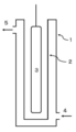
- One embodiment of the flow type photochemical reaction apparatus used in the present invention is shown in FIG.
- the flow type photochemical reaction device used in the present invention includes, for example, an outer cylinder, an inner cylinder, and a light source.
- the outer cylinder is preferably cylindrical and includes an introduction part and a recovery part.
- the inner cylinder is preferably a transparent cylindrical shape so that light can be transmitted, and includes a light source inside thereof.
- the gap defined by the outer cylinder and the inner cylinder is closed, and the reaction takes place in the closed gap.
- a mixture containing Compound B and a brominating agent is introduced into the reaction device from the introduction part of the outer cylinder, the reaction is performed by irradiating light, and the mixture containing Compound A is recovered from the recovery part.
- a material having high light reflection efficiency for example, aluminum
- the size of the outer cylinder and the inner cylinder is not particularly limited. The reaction temperature, reaction time, introduction rate and the like may be set.
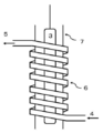
- the flow type photochemical reaction apparatus used in the present invention includes, for example, a reaction tube, a cylinder, and a light source.
- the reaction tube is a tube wound around a cylinder, and is preferably transparent so that light can be transmitted.
- One of the reaction tubes is an introduction part, and the other is a recovery part.
- the cylinder is preferably a transparent cylindrical shape so that light can be transmitted, and includes a light source inside thereof.
- a mixture containing Compound B and a brominating agent is introduced into a reaction tube and reacted by irradiating light to recover the mixture containing Compound A.
- the size of the reaction tube and the cylinder is not particularly limited. The reaction temperature, reaction time, introduction rate and the like may be set.
- a microreactor can be mentioned.
- HPLC measurement conditions are as follows. Detector: UV absorption photometer Measurement wavelength: 230nm Column: Symmetry C18 5 ⁇ m, inner diameter 4.6 x length 150mm Column temperature: 40 ° C Mobile phase: 50% acetonitrile buffer solution (0.05 mol / L phosphate buffer solution (pH 7.0)) Flow rate: 1mL / min
- NMR spectra were measured using tetramethylsilane as an internal standard and using JNM-AL400 type (manufactured by JEOL), and all ⁇ values were shown in ppm.
- Test example 1 Compound A was prepared from Compound B using a batch reaction. The reaction mixture was analyzed by HPLC, and the peak area ratio of each compound was determined. The results are shown below.
- Comparative Examples 1 to 3 are batch reactions that use 2,2′-azobis (2-methylpropionitrile) as a radical generator and do not use light.
- Comparative Example 4 is a batch reaction using a high-pressure mercury lamp.
- Test example 2 Compound A was prepared from Compound B using a flow reaction. The reaction mixture was analyzed by HPLC, and the peak area ratio of each compound was determined. The results are shown below.
- Example 1 is a reaction using ethyl acetate as a reaction solvent and NBS as a brominating agent.
- Examples 2 to 7 are reactions using ethyl acetate or methyl acetate as a reaction solvent and DBH as a brominating agent.
- Comparative Example 5 is a reaction using THF as a reaction solvent and DBH as a brominating agent. These are all flow-type photochemical reactions using a high-pressure mercury lamp.
- Test example 3 Compound A was prepared from Compound B using a flow reaction. The reaction mixture was analyzed by HPLC, and the peak area ratio of each compound was determined. The results are shown below.
- Examples 8 to 10 are flow photochemical reactions using LEDs as light sources. In all cases, the peak area ratio of Compound A was 79% or more, and there were few by-products. The flow-type photochemical reaction was excellent as an industrial production method of Compound A.
- Example 1 A solution of 1.1 g of 5-methyl-1-benzothiophene (Compound B) in 3.3 mL of ethyl acetate was prepared (Solution I). Separately, a solution of NBS 0.66 g in ethyl acetate 25 mL was prepared (Solution II). The flow rates of Solution I and Solution II were adjusted so that NBS was 1.1 equivalents relative to Compound B, and each solution was sent by a syringe pump to an in-line mixer to which an FEP tube having an inner diameter of 0.5 mm was connected. After mixing with the in-line mixer, the FEP tube was irradiated with a high-pressure mercury lamp (UMI-102 manufactured by Ushio).
- UMI-102 high-pressure mercury lamp
- the average residence time passing through the section irradiated with the high-pressure mercury lamp was 2 minutes. Further, a high-pressure mercury lamp around which the in-line mixer and the reaction tube were wound was immersed in a water bath, and the water temperature was kept at 30 ° C. When the HPLC measurement of the obtained reaction liquid was performed, the peak area ratio of the compound A was 90%. Table 2 shows the peak area ratios of Compound B, Compound C, and Compound D.
- Example 2 A solution of 2.00 g of 5-methyl-1-benzothiophene (Compound B) in 6 mL of ethyl acetate was prepared (Solution I). Separately, 90 mL of ethyl acetate in 3.18 g of DBH was prepared (solution II). The flow rates of Solution I and Solution II were adjusted so that DBH was 0.55 equivalent to Compound B, and each solution was sent by a syringe pump to an in-line mixer to which an FEP tube having an inner diameter of 0.5 mm was connected. After mixing with the in-line mixer, the FEP tube was irradiated with a high-pressure mercury lamp (UMI-102 manufactured by Ushio).
- UMI-102 high-pressure mercury lamp
- the average residence time passing through the section irradiated with the high-pressure mercury lamp was 1 minute. Further, a high-pressure mercury lamp around which the in-line mixer and the reaction tube were wound was immersed in a water bath, and the water temperature was maintained at 10 ° C. When the HPLC measurement of the obtained reaction liquid was performed, the peak area ratio of the compound A was 80%. Table 2 shows the peak area ratios of Compound B, Compound C, and Compound D.
- Example 3 The reaction was carried out in the same manner as in Example 2 except that the average residence time was 2 minutes and the water temperature of the water bath was maintained at 30 ° C. When the HPLC measurement of the obtained reaction liquid was performed, the peak area ratio of the compound A was 88%. Table 2 shows the peak area ratios of Compound B, Compound C, and Compound D.
- Example 4 The reaction was carried out in the same manner as in Example 2 except that the water temperature of the water bath was kept at 40 ° C. When the HPLC measurement of the obtained reaction liquid was performed, the peak area ratio of the compound A was 86%. Table 2 shows the peak area ratios of Compound B, Compound C, and Compound D.
- Example 5 A solution of 3.00 g of 5-methyl-1-benzothiophene (Compound B) in 4.5 mL of methyl acetate was prepared (Solution I). Separately, a 14 mL solution of DBH 1.06 g in methyl acetate was prepared (Solution II). The flow rates of Solution I and Solution II were adjusted so that DBH was 0.55 equivalent to Compound B, and each was sent to an in-line mixer connected with a FEP tube having an inner diameter of 0.5 mm by a syringe pump. After mixing with the in-line mixer, the FEP tube was irradiated with a high-pressure mercury lamp (UMI-102 manufactured by Ushio).
- UMI-102 high-pressure mercury lamp
- the average residence time passing through the section irradiated with the high-pressure mercury lamp was 2 minutes. Further, a high-pressure mercury lamp around which the in-line mixer and the reaction tube were wound was immersed in a water bath, and the water temperature was kept at 30 ° C. When the HPLC measurement of the obtained reaction liquid was performed, the peak area ratio of the compound A was 85%. Table 2 shows the peak area ratios of Compound B, Compound C, and Compound D.
- Example 6 The reaction was carried out in the same manner as in Example 5 except that the average residence time was 1 minute and the water temperature of the water bath was kept at 40 ° C. When the HPLC measurement of the obtained reaction liquid was performed, the peak area ratio of the compound A was 85%. Table 2 shows the peak area ratios of Compound B, Compound C, and Compound D.
- Example 7 A solution of 0.50 g of 5-methyl-1-benzothiophene (Compound B) in 1.5 mL of methylene chloride was prepared (Solution I). Separately, a 15 mL solution of 0.53 g DBH in methylene chloride was prepared (Solution II). The flow rates of Solution I and Solution II were adjusted so that DBH was 0.55 equivalent to Compound B, and each was sent to an in-line mixer connected with a FEP tube having an inner diameter of 0.5 mm by a syringe pump. After mixing with the in-line mixer, the FEP tube was irradiated with a high-pressure mercury lamp (UMI-102 manufactured by Ushio).
- UMI-102 high-pressure mercury lamp
- the average residence time passing through the section irradiated with the high-pressure mercury lamp was 1 minute. Further, a high-pressure mercury lamp around which the in-line mixer and the reaction tube were wound was immersed in a water bath, and the water temperature was kept at 30 ° C. When the HPLC measurement of the obtained reaction liquid was performed, the peak area ratio of the compound A was 81%. Table 2 shows the peak area ratios of Compound B, Compound C, and Compound D.
- Example 8 A solution of 0.40 g of 5-methyl-1-benzothiophene and 0.42 g of DBH in 13 mL of ethyl acetate was prepared. The obtained solution was sent by a syringe pump to a quartz channel plate having a rectangular channel having a depth of 1.0 mm and a width of 1.0 mm. The quartz channel plate was irradiated with light having a wavelength of 300 nm at room temperature using an LED lamp (Nikkiso 300 nm LED 3 ⁇ 3 array). The average residence time passing through the section irradiated with the LED lamp was 1 minute. When the HPLC measurement of the obtained reaction liquid was performed, the peak area ratio of the compound A was 79%. Table 3 shows the peak area ratios of Compound B, Compound C, and Compound D.
- Example 9 The reaction was carried out in the same manner as in Example 8 except that an LED lamp (MZeroLED manufactured by Integration Technology) was used as a light source and the light with a wavelength of 365 nm was irradiated.
- an LED lamp MZeroLED manufactured by Integration Technology
- the peak area ratio of the compound A was 84%.
- Table 3 shows the peak area ratios of Compound B, Compound C, and Compound D.
- Example 10 A reaction was carried out in the same manner as in Example 8 except that an LED lamp (233A manufactured by Matsuo Sangyo) was used as the light source and the light having a wavelength of 405 nm was irradiated. When the HPLC measurement of the obtained reaction liquid was performed, the peak area ratio of the compound A was 86%. Table 3 shows the peak area ratios of Compound B, Compound C, and Compound D.
- Comparative Example 3 9 mg of 2,2′-azobis (2-methylpropionitrile) was added to a mixture of 200 mg of 5-methyl-1-benzothiophene and 410 ml of NBS 410 mg in ethyl acetate, and the mixture was stirred for 30 minutes under reflux. When the HPLC measurement of the obtained reaction liquid was performed, the peak area ratio of the compound A was 78%. Table 1 shows the peak area ratios of Compound B, Compound C, and Compound D.
- Comparative Example 4 A mixture of 100 mg of 5-methyl-1-benzothiophene and 200 mL of NBS in ethyl acetate was stirred at 40 to 45 ° C. for 60 minutes while being irradiated with a high-pressure mercury lamp (UMI-102 manufactured by Ushio). When the HPLC measurement of the obtained reaction liquid was performed, the peak area ratio of the compound A was 71%. Table 1 shows the peak area ratios of Compound B, Compound C, and Compound D.
- Comparative Example 5 A 6 mL THF solution of 600 mg 5-methyl-1-benzothiophene and 640 mg DBH was prepared. The obtained solution was sent to a FEP tube having an inner diameter of 0.5 mm with a syringe pump, and irradiated with a high-pressure mercury lamp (UMI-102, manufactured by Ushio). The average residence time passing through the section irradiated with the high-pressure mercury lamp was 1 minute.
- a high-pressure mercury lamp wrapped with a reaction tube was immersed in a water bath, and the water temperature was maintained at 15 to 20 ° C. When the HPLC measurement of the obtained reaction liquid was performed, the peak area ratio of the compound A was 2%. Table 2 shows the peak area ratios of Compound B, Compound C, and Compound D.
- the production method of the present invention is useful as an industrial production method of 5-bromomethyl-1-benzothiophene, which is useful as an intermediate for the production of a medicine.
Landscapes
- Chemical & Material Sciences (AREA)
- Organic Chemistry (AREA)
- Physics & Mathematics (AREA)
- Electromagnetism (AREA)
- Health & Medical Sciences (AREA)
- General Health & Medical Sciences (AREA)
- Toxicology (AREA)
- Chemical Kinetics & Catalysis (AREA)
- Organic Low-Molecular-Weight Compounds And Preparation Thereof (AREA)
- Pharmaceuticals Containing Other Organic And Inorganic Compounds (AREA)
Abstract
Description
化合物Aは、医薬の中間体として、有用な化合物である。
一方、化合物Aの製造方法として、5-メチル-1-ベンゾチオフェン(以下、「化合物B」と称することがある。)を臭素化する方法が知られている(特許文献2~4)。
本発明の課題は、化合物Aの人体に影響がなく、簡便な化合物Aの工業的製造方法を提供することである。
本発明は、以下を提供する。
[3] 臭素化剤が、N-ブロモスクシンイミドおよび1,3-ジブロモ-5,5-ジメチルヒダントインから選ばれる一種または二種である、[1]に記載の、製造方法。
[4] 臭素化剤が、1,3-ジブロモ-5,5-ジメチルヒダントインである、[1]に記載の、製造方法。
[6] 溶媒が、酢酸メチルおよび酢酸エチルから選ばれる一種または二種である、[1]~[4]のいずれか一に記載の、製造方法。
[7] 反応温度が、5~70℃である、[1]~[6]のいずれか一に記載の、製造方法。
本発明の製造方法は、化合物Aの工業的製造方法として有用である。
2 内筒
3 光源
4 導入部
5 回収部
6 反応管
7 筒
本明細書中に使用される%は、特に断りのない限り、質量%を意味する。
エステル類とは、たとえば、酢酸メチル、酢酸エチル、酢酸プロピル、酢酸ブチルまたは酢酸イソアミルなどを意味する。

この反応は、フロー式光化学反応装置を用いて行われる。本発明の製造方法は、次の3つの工程を含む。
この工程は、化合物B、臭素化剤および溶媒を反応装置に導入する工程である。
この工程としては、たとえば、
(工程1A)化合物Bおよび溶媒を含む混合物ならびに臭素化剤および溶媒を含む混合物を反応装置に別々に導入しながら、反応装置内で混合する工程、
(工程1B)化合物B、臭素化剤および溶媒を含む混合物を調製した後、反応装置に導入する工程、
が挙げられる。
好ましい工程としては、(工程1B)が挙げられる。
より好ましい工程としては、
(a)化合物Bおよび溶媒を含む混合物を調製する工程、
(b)臭素化剤および溶媒を含む混合物を調製する工程、
(c)(a)および(b)で得られた混合物を混合する工程、
(d)(c)で得られた混合物を反応装置に導入する工程、
を含む工程が挙げられる。
化合物Bおよび溶媒を含む混合物は、化合物Bおよび溶媒を含む溶液であることが好ましい。
臭素化剤および溶媒を含む混合物は、臭素化剤および溶媒を含む溶液であることが好ましい。
化合物B、臭素化剤および溶媒を含む混合物は、化合物B、臭素化剤および溶媒を含む溶液であることが好ましい。
(a)および(b)で得られた混合物は、(a)および(b)で得られた溶液であることが好ましい。
(c)で得られた混合物は、(c)で得られた溶液であることが好ましい。
(c)の工程は、(d)の工程の直前で行うことが好ましい。
化合物Bは、溶解していることが好ましい。
臭素化剤の使用量は、臭素化剤の種類によって異なる。
たとえば、NBSを用いる場合、NBSの使用量は、化合物Bに対して、0.7~1.3等量であればよく、0.8~1.2等量が好ましく、0.9~1.2等量がより好ましく、1.0~1.2等量がさらに好ましい。
たとえば、DBHを用いる場合、化合物Bに対して、0.35~0.65等量であればよく、0.40~0.60等量が好ましく、0.45~0.60等量がより好ましく、0.50~0.60等量がさらに好ましい。
溶媒の使用量は、特に限定されないが、臭素化剤に対して、5~200倍量(v/w)であればよく、10~50倍量(v/w)が好ましい。
臭素化剤は、溶解していることが好ましい。
臭素化剤の使用量が、化合物Bに対して、上記の値になるように、臭素化剤の濃度を調整することが好ましい。
この工程は、光の照射下、反応装置に導入される化合物Bに臭素化剤を反応させる工程である。
化合物Bおよび臭素化剤を含む混合物に、光を照射する。光の照射には、光源を使用することが好ましい。
光源としては、キセノンランプ、太陽光、超高圧水銀ランプ、高圧水銀ランプ、低圧水銀ランプ、メタルハライドランプおよびLED(発光ダイオード)などが挙げられ、高圧水銀ランプ、メタルハライドランプおよびLEDが好ましい。
照射する光は、波長領域200~780nmの光であればよく、波長領域250~500nmの光が好ましく、波長領域300~450nmの光がより好ましい。
反応温度は、5~70℃であればよく、20~60℃が好ましい。
反応時間は、0.5~30分であればよく、0.7~15分が好ましく、1~5分がより好ましい。フロー式光化学反応装置を用いて行われるため、反応時間とは、反応装置内を通過する時間である。反応時間が上記の値になるように、導入速度を調整することが好ましい。
反応時間は、たとえば、反応が行われる空間容積と導入速度から求めることができる。
この工程は、反応によって生成した化合物Aを反応装置から回収する工程である。
化合物Aは、濃縮、留去、抽出、晶出および/またはカラムクロマトグラフィーなどの常法に従って、化合物Aを含む混合物から単離することができる。
化合物Aを用いて、さらに次の反応を行う場合、化合物Aは、単離することもできるが、単離せずに、そのまま次の工程に用いてもよい。
本発明に使用されるフロー式光化学反応装置の一態様を図1に示す。
本発明に使用されるフロー式光化学反応装置は、たとえば、外筒、内筒および光源を含む。
外筒は、円筒形であることが好ましく、導入部および回収部を含む。
内筒は、光が透過できるように、透明な円筒形であることが好ましく、その内側に光源を含む。
外筒および内筒によって区画された間隙は、閉鎖され、この閉鎖された間隙で反応が行われる。
化合物Bおよび臭素化剤を含む混合物を外筒の導入部から反応装置に導入し、光を照射して反応を行い、化合物Aを含む混合物を回収部から回収する。光源から照射された光を効率よく反応に寄与させるため、外筒の材質に光反射効率の高いもの(たとえば、アルミニウム)を選択してもよい。また、外筒の外側に光反射材を設けてもよい。
外筒および内筒の大きさは、特に制限されない。反応温度、反応時間および導入速度などを考慮して設定すればよい。
本発明に使用されるフロー式光化学反応装置は、たとえば、反応管、筒および光源を含む。
反応管は、筒に巻き付けられたチューブであり、光が透過できるように、透明であることが好ましい。反応管の一方が導入部であり、他方が回収部である。
筒は、光が透過できるように、透明な円筒形であることが好ましく、その内側に光源を含む。
化合物Bおよび臭素化剤を含む混合物を反応管に導入し、光を照射して反応を行い、化合物Aを含む混合物を回収する。
反応管および筒の大きさは、特に制限されない。反応温度、反応時間および導入速度などを考慮して設定すればよい。
Ac:アセチル
AcOEt:酢酸エチル
AcOMe:酢酸メチル
DBH:1,3-ジブロモ-5,5-ジメチルヒダントイン
eq:等量
Et:エチル
FEP:テトラフルオロエチレン・ヘキサフルオロプロピレン共重合体
HPLC:高速液体クロマトグラフィー
LED:発光ダイオード
Me:メチル
NBS:N-ブロモスクシンイミド
THF:テトラヒドロフラン
検出器:紫外吸光光度計
測定波長:230nm
カラム:Symmetry C18 5μm、内径4.6×長さ150mm
カラム温度:40℃
移動相:50%アセトニトリル緩衝溶液(0.05mol/Lリン酸緩衝溶液(pH7.0))
流量:1mL/分
バッチ式反応を用いて化合物Bから化合物Aを製造した。反応混合物をHPLCで分析し、各化合物のピーク面積比を求めた。結果を以下に示す。
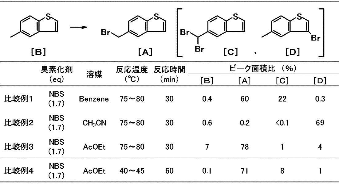
比較例4は、高圧水銀ランプを使用したバッチ式反応である。
反応溶媒としてアセトニトリルを用いた場合(比較例2)、多量の化合物Dが生成した。
反応溶媒として酢酸エチルを用いた場合(比較例3)、化合物Aのピーク面積比は78%であり、副生物が少なかった。
反応溶媒として酢酸エチルを用いて、高圧水銀ランプを使用したバッチ式反応の場合(比較例4)、ラジカル発生剤を必要とせず、反応温度を低下させることが可能になった。また、化合物Aのピーク面積比は71%であり、副生物が少なかった。
これまで、化合物Aを製造する方法において、反応溶媒として四塩化炭素が用いられてきたが、エステル類を用いても反応が進行することが見出された。さらに、高圧水銀ランプを使用した場合、ラジカル発生剤が必要でないこと、反応温度を低下させることができること、副生物が少ないことが見出された。
フロー式反応を用いて化合物Bから化合物Aを製造した。反応混合物をHPLCで分析し、各化合物のピーク面積比を求めた。結果を以下に示す。
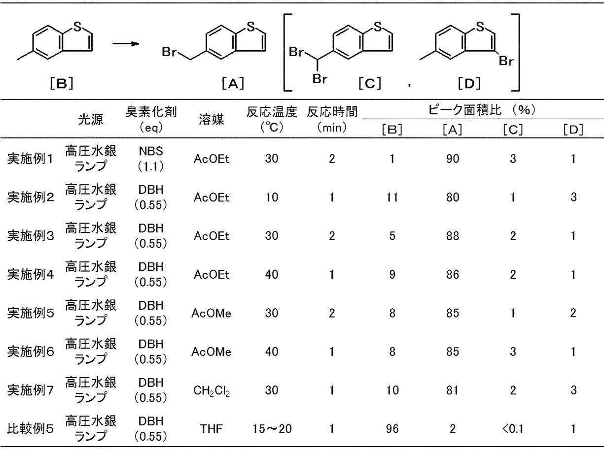
実施例2~7は、反応溶媒として酢酸エチルまたは酢酸メチルを、臭素化剤としてDBHを用いた反応である。
比較例5は、反応溶媒としてTHFを、臭素化剤としてDBHを用いた反応である。
これらは、いずれも高圧水銀ランプを用いたフロー式光化学反応である。
一方、実施例1~7の反応では、化合物Aのピーク面積比は80%以上であり、副生物が少なかった。また、バッチ式反応(比較例1~4)に比べ、反応温度を低下させることができ、反応時間を大幅に短縮させることが可能になった。
フロー式光化学反応は、化合物Aの工業的製造方法として優れていた。
フロー式反応を用いて化合物Bから化合物Aを製造した。反応混合物をHPLCで分析し、各化合物のピーク面積比を求めた。結果を以下に示す。

いずれも、化合物Aのピーク面積比は79%以上であり、副生物が少なかった。
フロー式光化学反応は、化合物Aの工業的製造方法として優れていた。

5-メチル-1-ベンゾチオフェン(化合物B)1.1gの酢酸エチル3.3mL溶液を調製した(溶液I)。別途、NBS0.66gの酢酸エチル25mL溶液を調製した(溶液II)。溶液Iおよび溶液IIを、NBSが化合物Bに対して1.1等量となるように流量を調整し、それぞれシリンジポンプにて、内径0.5mmのFEP製チューブが接続したインラインミキサーに送液した。インラインミキサーで混合した後、FEP製チューブに高圧水銀ランプ(ウシオ電機製UM―102)を照射した。なお、高圧水銀ランプに照射されている区間を通過する平均滞留時間を2分間とした。また、これらインラインミキサーおよび反応管を巻き付けた高圧水銀ランプをウォーターバスに浸漬させ、水温を30℃に保持させた。得られた反応液のHPLC測定を行ったところ、化合物Aのピーク面積比は90%であった。化合物B、化合物Cおよび化合物Dのピーク面積比を、表2に示す。

5-メチル-1-ベンゾチオフェン(化合物B)2.00gの酢酸エチル6mL溶液を調製した(溶液I)。別途、DBH3.18gの酢酸エチル90mL溶液を調製した(溶液II)。溶液Iおよび溶液IIを、DBHが化合物Bに対して0.55等量となるように流量を調整し、それぞれシリンジポンプにて、内径0.5mmのFEP製チューブが接続したインラインミキサーに送液した。インラインミキサーで混合した後、FEP製チューブに高圧水銀ランプ(ウシオ電機製UM―102)を照射した。なお、高圧水銀ランプに照射されている区間を通過する平均滞留時間を1分間とした。また、これらインラインミキサーおよび反応管を巻き付けた高圧水銀ランプをウォーターバスに浸漬させ、水温を10℃に保持させた。得られた反応液のHPLC測定を行ったところ、化合物Aのピーク面積比は80%であった。化合物B、化合物Cおよび化合物Dのピーク面積比を、表2に示す。
平均滞留時間を2分間とし、ウォーターバスの水温を30℃に保持させた以外は、実施例2と同様にして、反応を行った。
得られた反応液のHPLC測定を行ったところ、化合物Aのピーク面積比は88%であった。化合物B、化合物Cおよび化合物Dのピーク面積比を、表2に示す。
ウォーターバスの水温を40℃に保持させた以外は、実施例2と同様にして、反応を行った。
得られた反応液のHPLC測定を行ったところ、化合物Aのピーク面積比は86%であった。化合物B、化合物Cおよび化合物Dのピーク面積比を、表2に示す。
5-メチル-1-ベンゾチオフェン(化合物B)3.00gの酢酸メチル4.5mL溶液を調製した(溶液I)。別途、DBH1.06gの酢酸メチル14mL溶液を調製した(溶液II)。溶液Iおよび溶液IIを、DBHが化合物Bに対して0.55等量となるように流量を調整し、それぞれシリンジポンプにて内径0.5mmのFEP製チューブが接続したインラインミキサーに送液した。インラインミキサーで混合した後、FEP製チューブに高圧水銀ランプ(ウシオ電機製UM―102)を照射した。なお、高圧水銀ランプに照射されている区間を通過する平均滞留時間を2分間とした。また、これらインラインミキサーおよび反応管を巻き付けた高圧水銀ランプをウォーターバスに浸漬させ、水温を30℃に保持させた。得られた反応液のHPLC測定を行ったところ、化合物Aのピーク面積比は85%であった。化合物B、化合物Cおよび化合物Dのピーク面積比を、表2に示す。
平均滞留時間を1分間とし、ウォーターバスの水温を40℃に保持させた以外は、実施例5と同様にして、反応を行った。
得られた反応液のHPLC測定を行ったところ、化合物Aのピーク面積比は85%であった。化合物B、化合物Cおよび化合物Dのピーク面積比を、表2に示す。
5-メチル-1-ベンゾチオフェン(化合物B)0.50gの塩化メチレン1.5mL溶液を調製した(溶液I)。別途、DBH0.53gの塩化メチレン15mL溶液を調製した(溶液II)。溶液Iおよび溶液IIを、DBHが化合物Bに対して0.55等量となるように流量を調整し、それぞれシリンジポンプにて内径0.5mmのFEP製チューブが接続したインラインミキサーに送液した。インラインミキサーで混合した後、FEP製チューブに高圧水銀ランプ(ウシオ電機製UM―102)を照射した。なお、高圧水銀ランプに照射されている区間を通過する平均滞留時間を1分間とした。また、これらインラインミキサーおよび反応管を巻き付けた高圧水銀ランプをウォーターバスに浸漬させ、水温を30℃に保持させた。得られた反応液のHPLC測定を行ったところ、化合物Aのピーク面積比は81%であった。化合物B、化合物Cおよび化合物Dのピーク面積比を、表2に示す。
5-メチル-1-ベンゾチオフェン0.40gおよびDBH0.42gの酢酸エチル13mL溶液を調製した。得られた溶液をシリンジポンプにて、深さ1.0mm、幅1.0mmの矩形流路を形成した石英流路プレートに送液した。石英流路プレートに、室温で、LEDランプ(日機装製300nmLED3x3アレイ)を用いて波長300nmの光を照射した。なお、LEDランプに照射されている区間を通過する平均滞留時間を1分間とした。得られた反応液のHPLC測定を行ったところ、化合物Aのピーク面積比は79%であった。化合物B、化合物Cおよび化合物Dのピーク面積比を、表3に示す。
光源としてLEDランプ(IntegrationTechnology製MZeroLED)を用いて波長365nmの光を照射した以外は、実施例8と同様にして、反応を行った。
得られた反応液のHPLC測定を行ったところ、化合物Aのピーク面積比は84%であった。化合物B、化合物Cおよび化合物Dのピーク面積比を、表3に示す。
光源としてLEDランプ(松尾産業製233A)を用いて波長405nmの光を照射した以外は、実施例8と同様にして、反応を行った。
得られた反応液のHPLC測定を行ったところ、化合物Aのピーク面積比は86%であった。化合物B、化合物Cおよび化合物Dのピーク面積比を、表3に示す。
NBS2.04gおよび2,2’-アゾビス(2-メチルプロピオニトリル)22mgのベンゼン15mL混合物に、80℃で5-メチル-1-ベンゾチオフェン1.00gおよび2,2’-アゾビス(2-メチルプロピオニトリル)22mgのベンゼン9mL溶液を30分間かけて滴下し、同温度下で30分間撹拌した。得られた反応液のHPLC測定を行ったところ、化合物Aのピーク面積比は、60%であった。化合物B、化合物Cおよび化合物Dのピーク面積比を、表1に示す。
NBS410mgおよび2,2’-アゾビス(2-メチルプロピオニトリル)4mgのアセトニトリル3mL混合物に、80℃で5-メチル-1-ベンゾチオフェン200mgおよび2,2’-アゾビス(2-メチルプロピオニトリル)4mgのアセトニトリル3.6mL溶液を30分間かけて滴下し、同温度で30分間撹拌した。得られた反応液のHPLC測定を行ったところ、化合物Aのピーク面積比は、0.2%であった。化合物B、化合物Cおよび化合物Dのピーク面積比を、表1に示す。
5-メチル-1-ベンゾチオフェン200mgおよびNBS410mgの酢酸エチル10mL混合物に、2,2’-アゾビス(2-メチルプロピオニトリル)9mgを加え、還流下で30分間撹拌した。得られた反応液のHPLC測定を行ったところ、化合物Aのピーク面積比は、78%であった。化合物B、化合物Cおよび化合物Dのピーク面積比を、表1に示す。
5-メチル-1-ベンゾチオフェン100mgおよびNBS200mgの酢酸エチル10mL混合物に、40~45℃で高圧水銀ランプ(ウシオ電機製UM―102)を照射しながら60分間撹拌した。得られた反応液のHPLC測定を行ったところ、化合物Aのピーク面積比は71%であった。化合物B、化合物Cおよび化合物Dのピーク面積比を、表1に示す。
5-メチル-1-ベンゾチオフェン600mgおよびDBH640mgのTHF6mL溶液を調製した。得られた溶液をシリンジポンプにて、内径0.5mmのFEP製チューブに送液し、高圧水銀ランプ(ウシオ電機製UM―102)を照射した。なお、高圧水銀ランプに照射されている区間を通過する平均滞留時間を1分間とした。また、反応管を巻き付けた高圧水銀ランプをウォーターバスに浸漬させ、水温を15~20℃に保持させた。得られた反応液のHPLC測定を行ったところ、化合物Aのピーク面積比は2%であった。化合物B、化合物Cおよび化合物Dのピーク面積比を、表2に示す。
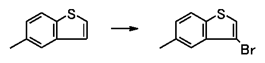
国際公開2012/073888号パンフレットに記載の方法を用いて、3-ブロモ-5-メチル-1-ベンゾチオフェンを得た。
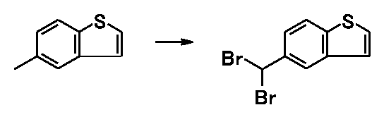
比較例1と同様な方法で得られた化合物Aと化合物Cの混合物を、シリカゲルカラムクロマトグラフィーで精製分離し、赤褐色固体の5-ジブロモメチル-1-ベンゾチオフェンを得た。
1H-NMR(CDCl3)δ値:7.45-7.52(2H,m),7.58(1H,d,J=8.3Hz),7.87(1H,d,J=8.5Hz),8.01(1H,d,J=5.6Hz),8.32(1H,s)

実施例6と同様な方法で、5-メチル-1-ベンゾチオフェン10.0gから化合物Aを製造した。得られた反応液を減圧下で溶媒を留去し、トルエンおよび水を加えた。有機層を分取し、飽和炭酸水素ナトリウム水溶液で洗浄した。有機層を分取し、減圧下で溶媒を留去した。得られた残留物に、水25mL、トルエン25mL、炭酸カリウム5.59g、シアンカリウム5.27gおよびテトラブチルアンモニウムブロミド650mgを加え、60℃で90分間撹拌した。反応混合物を室温まで冷却し、有機層を分取し、水で洗浄した。有機層を分取し、減圧下で溶媒を留去し、(1-ベンゾチオフェン-5-イル)アセトニトリルを得た。

製造例1で得られた(1-ベンゾチオフェン-5-イル)アセトニトリルに水15mL、プロピレングリコール10mLおよび水酸化ナトリウム6.48gを加え、90℃で3時間撹拌した。反応混合物を室温まで冷却し、水を加え、水層を分取した。得られた水層をトルエンで洗浄し、活性炭素0.5gを加え、50℃で10分間撹拌した。不溶物を濾去し、残渣を水で洗浄した。濾液と洗液を併せ、エタノール40mL、酢酸エチル6mL、水15mLおよび塩酸14mLを加えた。混合物を50℃まで加温した後、5℃まで冷却した。得られた混合物に、水を加え、固形物を濾取し、淡黄白色固体の(1-ベンゾチオフェン-5-イル)酢酸9.34gを得た。
1H-NMR(CDCl3)δ値:3.77(2H,s),7.24-7.32(1H,m),7.30(1H,d,J=5.5Hz),7.44(1H,d,J=5.5Hz),7.72-7.75(1H,m),7.84(1H,d,J=8.3Hz)

特開2012-046499号公報および国際公開2006/104088号パンフレットに記載の方法に従って、1-ベンゾチオフェン-5-酢酸を用いて、1-(3-(2-(1-ベンゾチオフェン-5-イル)エトキシ)プロピル)アゼチジン-3-オールを得た。
Claims (7)
- (1)5-メチル-1-ベンゾチオフェン、臭素化剤および溶媒を反応装置に導入する工程、
(2)反応装置の中へ、波長領域200~780nmの光を照射する工程、ならびに、
(3)5-ブロモメチル-1-ベンゾチオフェンを反応装置から回収する工程、
を含む、5-ブロモメチル-1-ベンゾチオフェンの製造方法であって、
反応装置が、フロー式光化学反応装置であり、
溶媒が、エステル類およびハロゲン化炭化水素類から選ばれる一種または二種以上である、製造方法。 - 臭素化剤が、臭素、N-ブロモカプロラクタム、N-ブロモスクシンイミド、1,3-ジブロモ-5,5-ジメチルヒダントイン、臭素-ピリジン錯体および臭化銅(II)から選ばれる一種または二種以上である、請求項1に記載の、製造方法。
- 臭素化剤が、N-ブロモスクシンイミドおよび1,3-ジブロモ-5,5-ジメチルヒダントインから選ばれる一種または二種である、請求項1に記載の、製造方法。
- 臭素化剤が、1,3-ジブロモ-5,5-ジメチルヒダントインである、請求項1に記載の、製造方法。
- 溶媒が、エステル類から選ばれる一種または二種以上である、請求項1~4のいずれか一項に記載の、製造方法。
- 溶媒が、酢酸メチルおよび酢酸エチルから選ばれる一種または二種である、請求項1~4のいずれか一項に記載の、製造方法。
- 反応温度が、5~70℃である、請求項1~6のいずれか一項に記載の、製造方法。
Priority Applications (9)
| Application Number | Priority Date | Filing Date | Title |
|---|---|---|---|
| CA3018486A CA3018486C (en) | 2016-03-31 | 2017-03-30 | Method for producing 5-(bromomethyl)-1-benzothiophene |
| AU2017239816A AU2017239816B9 (en) | 2016-03-31 | 2017-03-30 | Method for producing 5-(bromomethyl)-1-benzothiophene |
| EP17775384.5A EP3444243B1 (en) | 2016-03-31 | 2017-03-30 | Method for producing 5-(bromomethyl)-1-benzothiophene |
| JP2018509430A JP6804520B2 (ja) | 2016-03-31 | 2017-03-30 | 5−ブロモメチル−1−ベンゾチオフェンの製造方法 |
| CN201780021457.2A CN109526218B (zh) | 2016-03-31 | 2017-03-30 | 5-溴甲基-1-苯并噻吩的制备方法 |
| US16/089,633 US11236062B2 (en) | 2016-03-31 | 2017-03-30 | Method for producing 5-(bromomethyl)-1-benzothiophene |
| BR112018069438-0A BR112018069438B1 (pt) | 2016-03-31 | 2017-03-30 | Método para produzir 5- (bromometil) -1-benzotiofeno |
| KR1020187027309A KR102372969B1 (ko) | 2016-03-31 | 2017-03-30 | 5-브로모메틸-1-벤조티오펜의 제조방법 |
| RU2018138147A RU2733381C2 (ru) | 2016-03-31 | 2017-03-30 | Способ получения 5-(бромметил)-1-бензотиофена |
Applications Claiming Priority (2)
| Application Number | Priority Date | Filing Date | Title |
|---|---|---|---|
| JP2016-071574 | 2016-03-31 | ||
| JP2016071574 | 2016-03-31 |
Publications (1)
| Publication Number | Publication Date |
|---|---|
| WO2017170850A1 true WO2017170850A1 (ja) | 2017-10-05 |
Family
ID=59965861
Family Applications (1)
| Application Number | Title | Priority Date | Filing Date |
|---|---|---|---|
| PCT/JP2017/013206 Ceased WO2017170850A1 (ja) | 2016-03-31 | 2017-03-30 | 5-ブロモメチル-1-ベンゾチオフェンの製造方法 |
Country Status (10)
| Country | Link |
|---|---|
| US (1) | US11236062B2 (ja) |
| EP (1) | EP3444243B1 (ja) |
| JP (1) | JP6804520B2 (ja) |
| KR (1) | KR102372969B1 (ja) |
| CN (1) | CN109526218B (ja) |
| AU (1) | AU2017239816B9 (ja) |
| BR (1) | BR112018069438B1 (ja) |
| CA (1) | CA3018486C (ja) |
| RU (1) | RU2733381C2 (ja) |
| WO (1) | WO2017170850A1 (ja) |
Families Citing this family (4)
| Publication number | Priority date | Publication date | Assignee | Title |
|---|---|---|---|---|
| US11872556B2 (en) * | 2019-03-05 | 2024-01-16 | Dalian University Of Technology | General-purpose fluorescent fluid photochemical microreactor and manufacturing method therefor by 3D printing |
| EP4174049B1 (en) * | 2020-08-31 | 2025-11-26 | UBE Corporation | Method for producing 2-(halogenated methyl)naphthalene and 2-naphthyl acetonitrile |
| CN113480517B (zh) * | 2021-07-30 | 2022-09-09 | 海南海神同洲制药有限公司 | 3-溴甲基-7-氯苯并[b]噻吩的合成方法 |
| CN116903433A (zh) * | 2023-07-12 | 2023-10-20 | 安徽科芯微流化工科技有限公司 | 一种微通道反应制备全氟溴辛烷的方法 |
Citations (7)
| Publication number | Priority date | Publication date | Assignee | Title |
|---|---|---|---|---|
| JP2000515193A (ja) * | 1996-07-24 | 2000-11-14 | エクソン・ケミカル・パテンツ・インク | イソモノオレフィン/パラ―アルキルスチレンコポリマーのハロゲン化方法 |
| JP2001523658A (ja) * | 1997-11-17 | 2001-11-27 | サノフィ−サンテラボ | ブロモメチル−ビフェニル誘導体の製造方法 |
| JP2003523994A (ja) * | 2000-02-24 | 2003-08-12 | スミスクライン ビーチャム パブリック リミテッド カンパニー | 新規cd23インヒビター |
| JP2003532727A (ja) * | 2000-05-11 | 2003-11-05 | スミスクライン ビーチャム パブリック リミテッド カンパニー | Cd23の阻害剤としてのn−スルホニルヒドロキサム酸誘導体 |
| WO2003101983A1 (en) * | 2002-05-31 | 2003-12-11 | Yamanouchi Pharmaceutical Co., Ltd. | Tetrahydropyran derivative |
| JP2013121923A (ja) * | 2011-12-09 | 2013-06-20 | Mitsui Chemicals Agro Inc | 4,4−ジフルオロ−3,4−ジヒドロイソキノリン類の製造法 |
| WO2014125911A1 (ja) * | 2013-02-13 | 2014-08-21 | Jnc株式会社 | ジフルオロメチレンオキシを有する液晶性化合物、液晶組成物および液晶表示素子 |
Family Cites Families (16)
| Publication number | Priority date | Publication date | Assignee | Title |
|---|---|---|---|---|
| US3354066A (en) * | 1963-08-21 | 1967-11-21 | Dow Chemical Co | Allylic bromination process |
| US3567921A (en) * | 1967-02-09 | 1971-03-02 | Phillips Petroleum Co | Apparatus for the continjous photohalogenation of hydrocarbons |
| GB1483349A (en) * | 1974-02-28 | 1977-08-17 | Croda Synthetic Chem Ltd | Halogenation of heterocyclic compounds |
| US4046656A (en) * | 1976-12-06 | 1977-09-06 | The Dow Chemical Company | Photochlorination process for methyl aromatic compounds |
| US4235685A (en) * | 1979-09-04 | 1980-11-25 | Ethyl Corporation | Preparation of 3-thenyl bromide |
| JPS62138489A (ja) * | 1985-12-12 | 1987-06-22 | Tokuyama Soda Co Ltd | 臭素化チオフエンの製造方法 |
| EP0404721A3 (de) * | 1989-06-20 | 1991-12-27 | Ciba-Geigy Ag | Mikrobizide Mittel |
| ES2092737T3 (es) * | 1992-10-29 | 1996-12-01 | Hoechst Ag | Procedimiento para la preparacion de compuestos bromometil-aromaticos. |
| EP1792614A1 (en) * | 2001-02-22 | 2007-06-06 | Teijin Pharma Limited | Benzo[b]thiophene derivatives |
| EP1735302B1 (en) * | 2004-02-27 | 2010-06-16 | Eli Lilly And Company | 4-amino-piperidine derivatives as monoamine uptake inhibitors |
| KR20050092885A (ko) | 2004-03-17 | 2005-09-23 | 현대자동차주식회사 | 로프 후크 일체형 사이드 게이트 고정 장치 |
| JP2006111553A (ja) | 2004-10-13 | 2006-04-27 | Dainippon Sumitomo Pharma Co Ltd | スルホニルオキシインドール誘導体及びそれを含有する医薬組成物 |
| SI2348022T1 (sl) | 2005-03-28 | 2013-05-31 | Toyama Chemical Co., Ltd. | Postopek proizvodnje 1-(3-(2-(1-benzotiofen-5-il)etoksi)propil)azetidin-3-ola ali soli le-tega |
| KR20060104088A (ko) | 2005-03-29 | 2006-10-09 | 삼성전자주식회사 | 표시 장치의 회로 기판 및 이를 포함하는 표시 장치 |
| AU2007332968B2 (en) | 2006-05-22 | 2013-07-11 | Methylgene Inc. | Novel inhibitors of beta-lactamase |
| KR20080073142A (ko) | 2007-02-05 | 2008-08-08 | 삼성전자주식회사 | 다결정 실리콘 박막의 제조방법 |
-
2017
- 2017-03-30 EP EP17775384.5A patent/EP3444243B1/en active Active
- 2017-03-30 US US16/089,633 patent/US11236062B2/en active Active
- 2017-03-30 CA CA3018486A patent/CA3018486C/en active Active
- 2017-03-30 CN CN201780021457.2A patent/CN109526218B/zh active Active
- 2017-03-30 JP JP2018509430A patent/JP6804520B2/ja active Active
- 2017-03-30 WO PCT/JP2017/013206 patent/WO2017170850A1/ja not_active Ceased
- 2017-03-30 BR BR112018069438-0A patent/BR112018069438B1/pt active IP Right Grant
- 2017-03-30 AU AU2017239816A patent/AU2017239816B9/en active Active
- 2017-03-30 KR KR1020187027309A patent/KR102372969B1/ko active Active
- 2017-03-30 RU RU2018138147A patent/RU2733381C2/ru active
Patent Citations (7)
| Publication number | Priority date | Publication date | Assignee | Title |
|---|---|---|---|---|
| JP2000515193A (ja) * | 1996-07-24 | 2000-11-14 | エクソン・ケミカル・パテンツ・インク | イソモノオレフィン/パラ―アルキルスチレンコポリマーのハロゲン化方法 |
| JP2001523658A (ja) * | 1997-11-17 | 2001-11-27 | サノフィ−サンテラボ | ブロモメチル−ビフェニル誘導体の製造方法 |
| JP2003523994A (ja) * | 2000-02-24 | 2003-08-12 | スミスクライン ビーチャム パブリック リミテッド カンパニー | 新規cd23インヒビター |
| JP2003532727A (ja) * | 2000-05-11 | 2003-11-05 | スミスクライン ビーチャム パブリック リミテッド カンパニー | Cd23の阻害剤としてのn−スルホニルヒドロキサム酸誘導体 |
| WO2003101983A1 (en) * | 2002-05-31 | 2003-12-11 | Yamanouchi Pharmaceutical Co., Ltd. | Tetrahydropyran derivative |
| JP2013121923A (ja) * | 2011-12-09 | 2013-06-20 | Mitsui Chemicals Agro Inc | 4,4−ジフルオロ−3,4−ジヒドロイソキノリン類の製造法 |
| WO2014125911A1 (ja) * | 2013-02-13 | 2014-08-21 | Jnc株式会社 | ジフルオロメチレンオキシを有する液晶性化合物、液晶組成物および液晶表示素子 |
Non-Patent Citations (1)
| Title |
|---|
| See also references of EP3444243A4 * |
Also Published As
| Publication number | Publication date |
|---|---|
| JPWO2017170850A1 (ja) | 2019-02-07 |
| EP3444243B1 (en) | 2020-09-02 |
| US20190119242A1 (en) | 2019-04-25 |
| CN109526218A (zh) | 2019-03-26 |
| BR112018069438A2 (pt) | 2019-02-12 |
| CA3018486A1 (en) | 2017-10-05 |
| KR20180131544A (ko) | 2018-12-10 |
| US11236062B2 (en) | 2022-02-01 |
| JP6804520B2 (ja) | 2020-12-23 |
| BR112018069438B1 (pt) | 2022-07-05 |
| RU2018138147A (ru) | 2020-04-30 |
| AU2017239816B2 (en) | 2020-09-17 |
| CN109526218B (zh) | 2021-07-06 |
| EP3444243A4 (en) | 2019-09-11 |
| EP3444243A1 (en) | 2019-02-20 |
| KR102372969B1 (ko) | 2022-03-11 |
| RU2018138147A3 (ja) | 2020-05-27 |
| AU2017239816B9 (en) | 2020-09-24 |
| AU2017239816A1 (en) | 2018-10-04 |
| RU2733381C2 (ru) | 2020-10-01 |
| CA3018486C (en) | 2024-02-20 |
Similar Documents
| Publication | Publication Date | Title |
|---|---|---|
| US12275696B2 (en) | Process for preparing tapinarof | |
| JP6804520B2 (ja) | 5−ブロモメチル−1−ベンゾチオフェンの製造方法 | |
| WO2012010788A1 (fr) | Procede de preparation de derives d'amino-benzoyl-benzofurane | |
| CN1656064A (zh) | 亚磺酰乙酰胺的制备 | |
| JP2023011667A (ja) | スルホンアミド構造のキナーゼ阻害剤の製造方法 | |
| TWI539948B (zh) | 奧美沙坦酯之製造方法 | |
| JP2008201740A (ja) | エダラボンの精製方法及び高純度エダラボン | |
| JP2008511684A (ja) | アナストロゾール中間体についての精製方法 | |
| KR20040034718A (ko) | 3-브로모메틸벤조산의 제조 방법 | |
| JP2012144508A (ja) | トリフェニレン誘導体の製造法 | |
| HK1263035A1 (en) | Method for producing 5-(bromomethyl)-1-benzothiophene | |
| HK1263035B (en) | Method for producing 5-(bromomethyl)-1-benzothiophene | |
| JP5591556B2 (ja) | 新規含フッ素アクリル酸エステル誘導体及びその製造方法 | |
| CN114380783B (zh) | 一种奥洛他定氘标记代谢物的制备方法 | |
| US9815768B2 (en) | Method for producing 2-(halogenomethyl)-3-methylnitrobenzene | |
| JP6275596B2 (ja) | テルミサルタンのアンモニウム塩の製造方法 | |
| RU2565755C2 (ru) | Способ получения фотосенсибилизаторов на основе хлорина е6 | |
| JPH0324077A (ja) | イミダゾール誘導体の製法 | |
| WO2016052353A1 (ja) | ジェミナルジフルオロ化合物の製造方法 | |
| JP2003155282A (ja) | ベンゾフラン−2−カルボン酸類の製造方法 |
Legal Events
| Date | Code | Title | Description |
|---|---|---|---|
| ENP | Entry into the national phase |
Ref document number: 3018486 Country of ref document: CA Ref document number: 20187027309 Country of ref document: KR Kind code of ref document: A |
|
| WWE | Wipo information: entry into national phase |
Ref document number: 2018509430 Country of ref document: JP |
|
| NENP | Non-entry into the national phase |
Ref country code: DE |
|
| ENP | Entry into the national phase |
Ref document number: 2017239816 Country of ref document: AU Date of ref document: 20170330 Kind code of ref document: A |
|
| REG | Reference to national code |
Ref country code: BR Ref legal event code: B01A Ref document number: 112018069438 Country of ref document: BR |
|
| WWE | Wipo information: entry into national phase |
Ref document number: 2017775384 Country of ref document: EP |
|
| ENP | Entry into the national phase |
Ref document number: 2017775384 Country of ref document: EP Effective date: 20181031 |
|
| 121 | Ep: the epo has been informed by wipo that ep was designated in this application |
Ref document number: 17775384 Country of ref document: EP Kind code of ref document: A1 |
|
| ENP | Entry into the national phase |
Ref document number: 112018069438 Country of ref document: BR Kind code of ref document: A2 Effective date: 20180924 |