WO2017170902A1 - 電解コンデンサ及びその製造方法 - Google Patents
電解コンデンサ及びその製造方法 Download PDFInfo
- Publication number
- WO2017170902A1 WO2017170902A1 PCT/JP2017/013331 JP2017013331W WO2017170902A1 WO 2017170902 A1 WO2017170902 A1 WO 2017170902A1 JP 2017013331 W JP2017013331 W JP 2017013331W WO 2017170902 A1 WO2017170902 A1 WO 2017170902A1
- Authority
- WO
- WIPO (PCT)
- Prior art keywords
- cathode
- conductive polymer
- electrolytic capacitor
- polymer layer
- electrolytic
- Prior art date
- Legal status (The legal status is an assumption and is not a legal conclusion. Google has not performed a legal analysis and makes no representation as to the accuracy of the status listed.)
- Ceased
Links
Images


Classifications
-
- H—ELECTRICITY
- H01—ELECTRIC ELEMENTS
- H01G—CAPACITORS; CAPACITORS, RECTIFIERS, DETECTORS, SWITCHING DEVICES, LIGHT-SENSITIVE OR TEMPERATURE-SENSITIVE DEVICES OF THE ELECTROLYTIC TYPE
- H01G9/00—Electrolytic capacitors, rectifiers, detectors, switching devices, light-sensitive or temperature-sensitive devices; Processes of their manufacture
- H01G9/004—Details
- H01G9/04—Electrodes or formation of dielectric layers thereon
- H01G9/042—Electrodes or formation of dielectric layers thereon characterised by the material
- H01G9/0425—Electrodes or formation of dielectric layers thereon characterised by the material specially adapted for cathode
-
- H—ELECTRICITY
- H01—ELECTRIC ELEMENTS
- H01G—CAPACITORS; CAPACITORS, RECTIFIERS, DETECTORS, SWITCHING DEVICES, LIGHT-SENSITIVE OR TEMPERATURE-SENSITIVE DEVICES OF THE ELECTROLYTIC TYPE
- H01G9/00—Electrolytic capacitors, rectifiers, detectors, switching devices, light-sensitive or temperature-sensitive devices; Processes of their manufacture
- H01G9/0029—Processes of manufacture
-
- H—ELECTRICITY
- H01—ELECTRIC ELEMENTS
- H01G—CAPACITORS; CAPACITORS, RECTIFIERS, DETECTORS, SWITCHING DEVICES, LIGHT-SENSITIVE OR TEMPERATURE-SENSITIVE DEVICES OF THE ELECTROLYTIC TYPE
- H01G9/00—Electrolytic capacitors, rectifiers, detectors, switching devices, light-sensitive or temperature-sensitive devices; Processes of their manufacture
- H01G9/004—Details
- H01G9/022—Electrolytes; Absorbents
- H01G9/025—Solid electrolytes
- H01G9/028—Organic semiconducting electrolytes, e.g. TCNQ
-
- H—ELECTRICITY
- H01—ELECTRIC ELEMENTS
- H01G—CAPACITORS; CAPACITORS, RECTIFIERS, DETECTORS, SWITCHING DEVICES, LIGHT-SENSITIVE OR TEMPERATURE-SENSITIVE DEVICES OF THE ELECTROLYTIC TYPE
- H01G9/00—Electrolytic capacitors, rectifiers, detectors, switching devices, light-sensitive or temperature-sensitive devices; Processes of their manufacture
- H01G9/004—Details
- H01G9/022—Electrolytes; Absorbents
- H01G9/035—Liquid electrolytes, e.g. impregnating materials
-
- H—ELECTRICITY
- H01—ELECTRIC ELEMENTS
- H01G—CAPACITORS; CAPACITORS, RECTIFIERS, DETECTORS, SWITCHING DEVICES, LIGHT-SENSITIVE OR TEMPERATURE-SENSITIVE DEVICES OF THE ELECTROLYTIC TYPE
- H01G9/00—Electrolytic capacitors, rectifiers, detectors, switching devices, light-sensitive or temperature-sensitive devices; Processes of their manufacture
- H01G9/004—Details
- H01G9/04—Electrodes or formation of dielectric layers thereon
-
- H—ELECTRICITY
- H01—ELECTRIC ELEMENTS
- H01G—CAPACITORS; CAPACITORS, RECTIFIERS, DETECTORS, SWITCHING DEVICES, LIGHT-SENSITIVE OR TEMPERATURE-SENSITIVE DEVICES OF THE ELECTROLYTIC TYPE
- H01G9/00—Electrolytic capacitors, rectifiers, detectors, switching devices, light-sensitive or temperature-sensitive devices; Processes of their manufacture
- H01G9/004—Details
- H01G9/04—Electrodes or formation of dielectric layers thereon
- H01G9/042—Electrodes or formation of dielectric layers thereon characterised by the material
- H01G9/045—Electrodes or formation of dielectric layers thereon characterised by the material based on aluminium
-
- H—ELECTRICITY
- H01—ELECTRIC ELEMENTS
- H01G—CAPACITORS; CAPACITORS, RECTIFIERS, DETECTORS, SWITCHING DEVICES, LIGHT-SENSITIVE OR TEMPERATURE-SENSITIVE DEVICES OF THE ELECTROLYTIC TYPE
- H01G9/00—Electrolytic capacitors, rectifiers, detectors, switching devices, light-sensitive or temperature-sensitive devices; Processes of their manufacture
- H01G9/004—Details
- H01G9/04—Electrodes or formation of dielectric layers thereon
- H01G9/048—Electrodes or formation of dielectric layers thereon characterised by their structure
- H01G9/052—Sintered electrodes
-
- H—ELECTRICITY
- H01—ELECTRIC ELEMENTS
- H01G—CAPACITORS; CAPACITORS, RECTIFIERS, DETECTORS, SWITCHING DEVICES, LIGHT-SENSITIVE OR TEMPERATURE-SENSITIVE DEVICES OF THE ELECTROLYTIC TYPE
- H01G9/00—Electrolytic capacitors, rectifiers, detectors, switching devices, light-sensitive or temperature-sensitive devices; Processes of their manufacture
- H01G9/145—Liquid electrolytic capacitors
Definitions
- the present invention relates to an electrolytic capacitor including a cathode that exhibits a high capacity, and a method for manufacturing the same.
- An electrolytic capacitor having an ion conductive electrolyte generally includes an anode in which an oxide film as a dielectric layer is provided on the surface of a valve metal foil such as aluminum, tantalum, or niobium, and a valve.
- a current collecting cathode (apparent cathode) composed of a metal foil or the like and a separator holding an ion conductive electrolyte as a true cathode disposed between the anode and the cathode are accommodated in a sealed case.
- a structure having a winding shape, a laminated shape, or the like is widely used.
- This electrolytic capacitor has the advantage that it is small and has a large capacity compared to plastic capacitors, mica capacitors, etc., and the dielectric breakdown voltage of the capacitor can be improved by thickening the oxide film on the anode.
- the oxide film on the anode is made thick, the capacity of the electrolytic capacitor is reduced, and some of the advantages of small size and large capacity are lost. Therefore, various studies have been made for the purpose of improving the capacity without lowering the dielectric breakdown voltage of the electrolytic capacitor. For example, chemical or electrochemical etching treatment is applied to the valve metal foil constituting the anode and the cathode. By controlling the conditions for applying the above, studies have been made to effectively increase the surface area of these valve metal foils and increase the capacity of not only the anode but also the cathode.
- Patent Document 1 Japanese Patent Publication No. 3-37293 discloses that, in an aluminum electrolytic capacitor, when etching is excessive, dissolution of the aluminum foil surface into the etching solution simultaneously proceeds, and on the contrary, an increase in the surface area of the foil is prevented.
- a cathode material for solving the problem that there is a limit in the capacity increase of the cathode by etching the average particle size of the surface of the appropriately roughened aluminum foil formed in an inert atmosphere such as argon or helium is 0.
- a cathode material is disclosed which is coated with a 0.2-5.0 ⁇ m thick titanium vapor deposition film composed of 02-1.0 ⁇ m fine titanium particles.
- the surface of the titanium vapor deposition film is finely roughened, so that the surface area of the cathode material is increased, and as a result, the capacity of the aluminum electrolytic capacitor is increased. Moreover, the cathode material excellent in durability is obtained by the titanium vapor deposition film.
- an object of the present invention is to provide an electrolytic capacitor having a cathode exhibiting a high capacity and a method for manufacturing the same, which can respond to the demand for miniaturization and high capacity by increasing the capacity per unit volume of the electrolytic capacitor. Is to provide.
- the inventors have found that when an electrolytic capacitor is configured using a cathode in which a conductive polymer layer is formed on a conductive substrate, the conductive polymer layer in contact with the ion conductive electrolyte in the capacitor is redoxed. As a result, the inventors discovered that the capacity per unit volume of the capacitor is remarkably increased, thereby completing the invention.
- the present invention first A cathode having a conductive substrate and a conductive polymer layer provided on the surface of the conductive substrate; A substrate made of a valve metal and a dielectric layer made of an oxide of the valve metal provided on the surface of the substrate, and the dielectric layer and the conductive polymer layer of the cathode open a space.
- An anode arranged so as to oppose, An ion conductive electrolyte filling the space;
- An electrolytic capacitor comprising:
- the present invention relates to an electrolytic capacitor, wherein a voltage is applied between the anode and the cathode, whereby the conductive polymer layer of the cathode that is in contact with the ion conductive electrolyte exhibits a redox capacity.
- the cathode having a conductive polymer layer in the electrolytic capacitor of the present invention exhibits a significantly increased capacity due to the development of redox capacity as compared with a cathode not having a conductive polymer layer, and thus the unit of the electrolytic capacitor Significantly increase capacity per volume.
- the cathode conductive polymer layer needs to be in direct contact with the ion conductive electrolyte in order to develop redox capacity, but the anode dielectric layer may be in direct contact with the ion conductive electrolyte. It may be indirectly connected to the ion conductive electrolyte through the conductive material. Moreover, the ion conductive electrolyte may be hold
- the conductive substrate of the cathode has a titanium vapor deposition film, and the conductive polymer layer is provided on the surface of the titanium vapor deposition film.
- the titanium vapor deposition film provides a cathode with excellent durability.
- a conductive polymer derived from a monomer having a known ⁇ -conjugated double bond can be used without any particular limitation.
- the conductive polymer layer is poly (3,4-ethylenedioxythiophene) (hereinafter 3,4-ethylenedioxythiophene is represented as “EDOT”, and poly (3,4-ethylenedioxythiophene is represented as “PEDOT”). It is preferable that PEDOT has a high redox activity and is excellent in heat resistance, and can be preferably used in the present invention.
- the size of the cathode or anode can be reduced, and consequently the capacity per unit volume of the electrolytic capacitor can be improved.
- the thickness of the conductive polymer layer of the cathode is preferably in the range of 200 to 2450 nm. When the thickness of the conductive polymer layer is less than 200 nm, the high-temperature durability tends to decrease, and when the thickness of the conductive polymer layer is greater than 2450 nm, the temperature dependency of the capacity increases. This makes it difficult to contribute to the downsizing of electrolytic capacitors.
- the conductive polymer layer on the negative electrode conductive substrate may be formed by electrolytic polymerization or chemical polymerization, and a dispersion containing conductive polymer particles may be formed on the conductive substrate. Although it may be formed by applying to the surface, it is preferably formed by electrolytic polymerization. By electropolymerization, a conductive polymer layer having excellent mechanical strength can be formed in a short time from a small amount of monomer on the surface of the substrate. Electropolymerization gives a thin, dense and uniform conductive polymer layer, and a suitable conductive polymer layer having a thickness in the range of 200 to 2450 nm can be easily obtained.
- the present invention is also a method for producing the above-described electrolytic capacitor of the present invention, Forming a conductive polymer layer on the surface of the conductive substrate to obtain a cathode for the electrolytic capacitor; Forming a dielectric layer made of the valve metal oxide by oxidizing the surface of the base made of the valve metal to obtain an anode for the electrolytic capacitor; and A method for producing an electrolytic capacitor, comprising: an electrolyte filling step, wherein the conductive polymer layer of the cathode and the dielectric layer of the anode are opposed to each other with a space therebetween, and the space is filled with an ion conductive electrolyte. About. In this method, it is preferable to form the conductive polymer layer in the cathode forming step by electrolytic polymerization.
- the electrolytic capacitor of the present invention by applying a voltage between the anode and the cathode, the conductive polymer layer of the cathode that is in contact with the ion conductive electrolyte develops a redox capacity, and the unit volume of the electrolytic capacitor The per capacities increase significantly. Therefore, the electrolytic capacitor can be reduced in size and increased in capacity.
- the electrolytic capacitor of the present invention includes a cathode having a conductive substrate, a conductive polymer layer provided on the surface of the conductive substrate, a substrate made of a valve metal, and the valve provided on the surface of the substrate.
- An electrolytic capacitor comprising an ion conductive electrolyte, wherein the cathode has a conductive polymer layer in contact with the ion conductive electrolyte by applying a voltage between the anode and the cathode.
- This capacitor can be manufactured by the following cathode forming step, anode forming step, and electrolyte filling step. Hereinafter, each step will be described in detail.
- the cathode in the electrolytic capacitor of the present invention has a conductive substrate and a conductive polymer layer provided on the surface of the conductive substrate.
- Any conductive substrate can be used without particular limitation as long as it can be used as a current collector.
- valve metal foils such as aluminum, tantalum, niobium, titanium and zirconium used for cathodes in conventional electrolytic capacitors, or chemical or electrochemical etching treatments for these valve metal foils.
- Foil having an increased surface area by application can be used as a substrate, and an oxide film may be present on the surface of these foils.
- a conductive material such as carbon, titanium, platinum, gold, silver, cobalt, nickel, iron or the like is vacuum applied to the surface of the valve metal foil or the surface of the oxide film of the valve metal foil having an oxide film.
- a substrate having a structure laminated by means of vapor deposition, sputtering, ion plating, coating or the like can also be suitably used.
- the oxide film on the valve metal foil may be a natural oxide film, or a film formed by a chemical conversion treatment using a chemical conversion solution such as an aqueous solution of ammonium borate, an aqueous solution of ammonium adipate, or an aqueous solution of ammonium phosphate. Also good.
- an alloy such as an aluminum-copper alloy can be used as the conductive substrate.
- a substrate with a titanium film laminated on the surface of an aluminum foil that has been subjected to etching treatment or an aluminum oxide film of an aluminum foil provided with an aluminum oxide film has a highly durable cathode. It is preferable to give.
- a vapor deposition technique is preferable, and the titanium vapor deposition film can contain atoms in the ambient atmosphere in the vapor deposition treatment, and can contain, for example, nitrogen or carbon.
- a titanium vapor deposition film containing carbon is preferable because it gives a polymer film exhibiting stable characteristics in the following electropolymerization.
- a conductive polymer layer is provided on the surface of the substrate.
- the conductive polymer layer may be an electrolytic polymer film, a chemical polymer film, or a dispersion containing at least conductive polymer particles and a dispersion medium.
- the formation of the electrolytic polymer film is performed by introducing the substrate and the counter electrode into a polymerization solution containing at least a monomer, a supporting electrolyte, and a solvent, and applying a voltage between the substrate and the counter electrode.
- a plate or net of platinum, nickel, steel or the like can be used as the counter electrode.
- an anion released from the supporting electrolyte is contained in the conductive polymer layer as a dopant.
- a solvent that can dissolve a desired amount of the monomer and the supporting electrolyte and does not adversely affect the electrolytic polymerization can be used without any particular limitation.
- examples include water, methanol, ethanol, isopropanol, butanol, ethylene glycol, acetonitrile, butyronitrile, acetone, methyl ethyl ketone, tetrahydrofuran, 1,4-dioxane, ⁇ -butyrolactone, methyl acetate, ethyl acetate, methyl benzoate, ethyl benzoate , Ethylene carbonate, propylene carbonate, nitromethane, nitrobenzene, sulfolane, dimethyl sulfolane.
- solvents may be used alone or in combination of two or more. It is preferable to use a solvent containing water in an amount of 80% by mass or more of the whole solvent, in particular, a solvent composed only of water, because a dense and stable electropolymerized film can be obtained.
- a monomer having a ⁇ -conjugated double bond conventionally used for producing a conductive polymer can be used without any particular limitation. Examples of typical monomers are shown below. These monomers may be used alone or as a mixture of two or more.
- thiophene and thiophene derivatives for example, 3-alkylthiophene such as 3-methylthiophene and 3-ethylthiophene, 3,4-dialkylthiophene such as 3,4-dimethylthiophene and 3,4-diethylthiophene, 3-methoxy 3-alkoxythiophene such as thiophene, 3-ethoxythiophene, 3,4-dialkoxythiophene, 3,4-dialkoxythiophene such as 3,4-diethoxythiophene, 3,4-methylenedioxythiophene, EDOT, 3, 3,4-alkylenedioxythiophene such as 4- (1,2-propylenedioxy) thiophene, 3,4-methyleneoxythiathiophene, 3,4-ethyleneoxythiathiophene, 3,4- (1,2- 3,4-alkyleneoxy such as propyleneoxythia) thiophene 3,4-alkylenedithiathiathi
- N-alkylpyrrole such as N-methylpyrrole and N-ethylpyrrole
- 3-alkylpyrrole such as 3-methylpyrrole and 3-ethylpyrrole
- 3-methoxypyrrole 3-ethoxypyrrole
- 3-alkoxypyrrole N-phenylpyrrole, N-naphthylpyrrole, 3,4-dimethylpyrrole, 3,4-diethylpyrrole, 3,4-dialkylpyrrole, 3,4-dimethoxypyrrole, 3,4- Mention may be made of 3,4-dialkoxypyrrole such as diethoxypyrrole.
- aniline and aniline derivatives such as 2,5-dialkylaniline such as 2,5-dimethylaniline and 2-methyl-5-ethylaniline, 2,5-dimethoxyaniline, 2-methoxy-5-ethoxyaniline and the like 2,3,5-trialkoxyaniline such as 2,5-dialkoxyaniline, 2,3,5-trimethoxyaniline, 2,3,5-triethoxyaniline, 2,3,5,6-tetramethoxyaniline 2,3,5,6-tetraalkoxyaniline such as 2,3,5,6-tetraethoxyaniline, and furan and furan derivatives such as 3-alkylfuran such as 3-methylfuran and 3-ethylfuran 3,4-Dimethylfuran such as 3,4-dimethylfuran, 3,4-diethylfuran, 3-methoxyfuran, 3-ethoxyfuran 3-alkoxy furan etc., 3,4-dimethoxy furan, mention may be made of 3,4-dialkoxy furan such as
- the monomer it is preferable to use a monomer selected from the group consisting of thiophene having substituents at the 3-position and 4-position.
- the substituents at the 3-position and 4-position of the thiophene ring may form a ring together with the carbons at the 3-position and 4-position.
- EDOT is preferable because it exhibits high redox activity and provides PEDOT with excellent heat resistance.
- a compound that releases a dopant contained in a conventional conductive polymer can be used without any particular limitation.
- inorganic acids such as boric acid, nitric acid, phosphoric acid, tungstophosphoric acid, molybdophosphoric acid
- organic acids such as acetic acid, oxalic acid, citric acid, ascot acid, tartaric acid, squaric acid, rhodizone acid, croconic acid, salicylic acid Methanesulfonic acid, dodecylsulfonic acid, trifluoromethanesulfonic acid, p-toluenesulfonic acid, dodecylbenzenesulfonic acid, 1,2-dihydroxy-3,5-benzenedisulfonic acid, naphthalenesulfonic acid, naphthalene disulfonic acid, propylnaphthalene
- inorganic acids such as boric acid, nitric acid, phosphoric acid,
- Polycarboxylic acids such as polyacrylic acid, polymethacrylic acid, and polymaleic acid
- polysulfonic acids such as polystyrene sulfonic acid and polyvinyl sulfonic acid, and salts thereof can also be used as the supporting electrolyte.
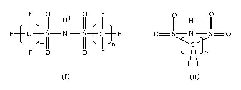
- borodisalicylic acid borodisuccinic acid, borodimalonic acid, borodisuccinic acid, borodiadipic acid, borodimaleic acid, borodiglycolic acid, borodilactic acid, borodihydroxyisobutyric acid, borodimalic acid, boroditartaric acid, borodicitric acid, borodiphthalic acid, borodihydroxybenzoic acid Boron complexes such as borodimandelic acid, borodibenzylic acid, formula (I) or formula (II) (In the formula, m means an integer of 1 to 8, preferably an integer of 1 to 4, particularly preferably 2, and n means an integer of 1 to 8, preferably an integer of 1 to 4, particularly preferably 2. And o means an integer of 2 or 3, and salts thereof can also be used as the supporting electrolyte.
- the salt examples include alkali metal salts such as lithium salt, sodium salt and potassium salt, alkyl ammonium salts such as ammonium salt, ethyl ammonium salt and butyl ammonium salt, dialkyl ammonium salts such as diethyl ammonium salt and dibutyl ammonium salt, and triethyl ammonium salt.
- alkali metal salts such as lithium salt, sodium salt and potassium salt
- alkyl ammonium salts such as ammonium salt, ethyl ammonium salt and butyl ammonium salt
- dialkyl ammonium salts such as diethyl ammonium salt and dibutyl ammonium salt
- triethyl ammonium salt examples include trialkylammonium salts such as tributylammonium salt, and tetraalkylammonium salts such as tetraethylammonium salt and tetrabutylammonium salt.
- These supporting electrolytes may be used alone or in combination of two or more. Depending on the type of the supporting electrolyte, the amount is less than the saturation solubility in the polymerization solution and for electrolytic polymerization.
- the concentration is such that a sufficient current can be obtained, preferably at a concentration of 10 mmol or more per liter of water.
- the electrolytic polymerization in the electrolytic polymerization is performed by any one of a constant potential method, a constant current method, and a potential sweep method.
- a constant potential method depending on the type of monomer, a potential of 1.0 to 1.5 V is suitable for the saturated calomel electrode, and in the case of the constant current method, it depends on the type of monomer.
- a current value of 1 to 10000 ⁇ A / cm 2 is suitable, and in the case of the potential sweep method, depending on the type of monomer, the range of 0 to 1.5 V with respect to the saturated calomel electrode is 5 to 200 mV / It is preferred to sweep at a rate of seconds.
- a conductive polymer layer is preferably formed on the substrate with a thickness of 200 to 2450 nm.
- the polymerization temperature is not strictly limited, but is generally in the range of 10 to 60 ° C.
- the polymerization time is not strictly limited, but is generally in the range of 1 minute to 10 hours.
- the chemical polymerization film is formed by preparing a solution in which both a monomer and an oxidizing agent are dissolved in a solvent, and applying this solution to the surface of the conductive substrate by brush coating, dripping coating, dip coating, spray coating, etc.
- Examples of the solvent include water, methanol, ethanol, isopropanol, butanol, ethylene glycol, acetonitrile, butyronitrile, acetone, methyl ethyl ketone, tetrahydrofuran, 1,4-dioxane, ⁇ -butyrolactone, methyl acetate, ethyl acetate, methyl benzoate, benzoate Ethyl acid, ethylene carbonate, propylene carbonate, nitromethane, nitrobenzene, sulfolane, dimethyl sulfolane can be used. These solvents may be used alone or in combination of two or more.
- a monomer having a ⁇ -conjugated double bond for example, a monomer exemplified for electrolytic polymerization can be used. These monomers may be used alone or as a mixture of two or more.
- a monomer selected from thiophene having substituents at the 3-position and 4-position is preferable, and EDOT is particularly preferable.
- the oxidizing agent include trivalent iron salts such as iron (III) p-toluenesulfonate, iron (III) naphthalenesulfonate, and iron (III) anthraquinonesulfonate, or ammonium peroxodisulfate and sodium peroxodisulfate.
- a persulfate or the like can be used, and a single compound may be used, or two or more compounds may be used.
- the polymerization temperature is not strictly limited, but is generally in the range of 10 to 60 ° C.
- the polymerization time is not strictly limited, but is generally in the range of 1 minute to 10 hours.
- a conductive polymer layer may be formed by applying a dispersion containing at least conductive polymer particles and a dispersion medium to the surface of the conductive substrate by means such as coating, dropping, and drying.
- the dispersion medium in the dispersion include water, methanol, ethanol, isopropanol, butanol, ethylene glycol, acetonitrile, butyronitrile, acetone, methyl ethyl ketone, tetrahydrofuran, 1,4-dioxane, ⁇ -butyrolactone, methyl acetate, ethyl acetate, Methyl benzoate, ethyl benzoate, ethylene carbonate, propylene carbonate, nitromethane, nitrobenzene, sulfolane, dimethylsulfolane can be used, but water is preferably used as a dispersion medium.
- the dispersion is prepared by adding, for example, a monomer, an acid or a salt thereof that releases a dopant, and an oxidizing agent to water, stirring until chemical oxidative polymerization is completed, and then performing ultrafiltration, cation exchange, In addition, after removing the oxidant and the residual monomer by a purification means such as anion exchange, it can be obtained by performing a dispersion treatment such as an ultrasonic dispersion treatment, a high-speed fluid dispersion treatment, a high-pressure dispersion treatment or the like as necessary.
- a dispersion treatment such as an ultrasonic dispersion treatment, a high-speed fluid dispersion treatment, a high-pressure dispersion treatment or the like as necessary.
- a monomer and an acid or a salt thereof that releases a dopant are added to water, and electrolytic oxidation polymerization is performed while stirring, and then the residual monomer is removed by purification means such as ultrafiltration, cation exchange, and anion exchange. After removal, it can be obtained by performing dispersion treatment such as ultrasonic dispersion treatment, high-speed fluid dispersion treatment, and high-pressure dispersion treatment as necessary.
- the liquid obtained by the above-described chemical oxidative polymerization method or electrolytic polymerization method is filtered to separate aggregates, washed thoroughly and then added to water, ultrasonic dispersion treatment, high-speed fluid dispersion treatment, high-pressure dispersion treatment It can be obtained by performing a dispersion process such as.
- the content of the conductive polymer particles in the dispersion is generally in the range of 1.0 to 3.0% by mass, and preferably in the range of 1.5 to 2.0% by mass. .
- the thickness of the conductive polymer layer of the cathode is preferably in the range of 200 to 2450 nm.
- the thickness of the conductive polymer layer is less than 200 nm, the high-temperature durability tends to decrease, and when the thickness of the conductive polymer layer is greater than 2450 nm, the temperature dependency of the capacity increases. This makes it difficult to contribute to the downsizing of electrolytic capacitors.
- the conductive polymer layer of the cathode is preferably formed by electrolytic polymerization.
- electropolymerization By electropolymerization, a conductive polymer layer having excellent mechanical strength can be formed in a short time from a small amount of monomer on the surface of the conductive substrate. Electropolymerization gives a thin, dense and uniform conductive polymer layer, and a suitable conductive polymer layer having a thickness in the range of 200 to 2450 nm can be easily obtained.
- the chemically polymerized film is not suitable for downsizing of the capacitor because the film quality is not uniform and the thickness is about 3 ⁇ m even if it is thin.
- the anode in the electrolytic capacitor of the present invention is composed of a base made of a valve metal such as aluminum, tantalum, niobium, titanium, or zirconium, and a dielectric made of an oxide of the valve metal provided on the surface of the base. And a body layer.
- the substrate for the anode is preferably one in which the surface area is increased by subjecting the valve metal foil to a chemical or electrochemical etching treatment by a known method, and an aluminum foil subjected to the etching treatment is particularly preferred.
- the dielectric layer on the surface of the substrate can be formed by a known method in which the substrate is subjected to a chemical conversion treatment using a chemical conversion solution such as an ammonium borate aqueous solution, an ammonium adipate aqueous solution, or an ammonium phosphate aqueous solution.
- a chemical conversion solution such as an ammonium borate aqueous solution, an ammonium adipate aqueous solution, or an ammonium phosphate aqueous solution.
- Electrolyte filling step In this step, the cathode obtained in the cathode formation step and the anode obtained in the anode formation step are separated from each other by a space between the cathode conductive polymer layer and the anode dielectric layer. After opening and arranging so as to face each other, the space is filled with an ion conductive electrolyte.
- an electrolytic solution used for a conventional electrolytic capacitor for example, phthalic acid in a solvent such as ⁇ -butyrolactone, ⁇ -valerolactone, ethylene glycol, ethylene glycol monomethyl ether, sulfolane, propylene carbonate, acetonitrile, water, etc.
- An electrolytic solution in which a solute such as a salt, salicylate, benzoate, adipate, maleate or borate is dissolved can be used.
- the salt examples include amidinium salt, imidazolinium salt, pyrimidinium salt, phosphonium salt, ammonium salt, amine salt, alkali metal salt and the like.
- the solvent of the electrolytic solution may be a single compound or a mixture of two or more kinds, and the solute may be a single compound or a mixture of two or more kinds.
- These electrolytic solutions may contain a gelling agent.
- a room temperature molten salt (ionic liquid) can be used as the ion conductive electrolyte.
- the capacitor element formed by laminating the strip-shaped cathode and the anode so that the conductive polymer layer of the cathode and the dielectric layer of the anode face each other with a separator interposed therebetween is wound on the capacitor element.
- This step can be carried out by impregnating with an electrolytic solution or an ionic liquid.
- the electrolytic solution or the ionic liquid is applied to a capacitor element formed by laminating the cathode and anode having a desired shape with a separator such that the conductive polymer layer of the cathode and the dielectric layer of the anode face each other.
- This step can be carried out by impregnating.
- Capacitor elements in which a plurality of sets of cathodes and anodes are alternately laminated so that the cathode conductive polymer layer and the anode dielectric layer face each other with the separator interposed therebetween are impregnated with the electrolytic solution or the ionic liquid.
- separators in addition to woven or non-woven fabrics made of cellulosic fibers, such as manila paper, kraft paper, esparto paper, hemp paper, cotton paper and mixed papers thereof, synthetic fiber paper, glass paper, glass paper And a mixed paper of Manila paper and kraft paper can be used.
- the impregnation with the electrolytic solution or the ionic liquid may be performed after the capacitor element is accommodated in an exterior case having an opening.
- the electrolytic solution can be made into a gel by heating after impregnating the capacitor element with the electrolytic solution.
- the ion conductive electrolyte is filled.
- This step may be performed.
- a gel electrolyte in addition to the electrolyte solution or the ionic liquid, a gel electrolyte in which the electrolyte solution is absorbed in polyvinylidene fluoride, polyacrylonitrile or the like, or the above-described salt and polyethylene oxide
- a solid electrolyte composed of a complex with a polymer compound such as polymethacrylate or polyacrylate can also be used.
- a gel-like or solid electrolyte may be laminated on the conductive polymer layer of the cathode, and then the anode may be laminated on the electrolyte so that the dielectric layer is in contact therewith.
- the conductive polymer layer of the cathode needs to be in direct contact with the ion conductive electrolyte, and the conductive polymer layer of the cathode is not in direct contact with the anode and is connected to the anode through the ion conductive electrolyte.
- the dielectric layer of the anode may be in direct contact with the ion conductive electrolyte, or may be indirectly connected to the ion conductive electrolyte through another conductive material. Examples of other suitable conductive materials include a conductive polymer layer.
- the conductive polymer layer can be formed on the surface of the anode dielectric layer by electrolytic polymerization or chemical polymerization after forming the anode in the anode forming step. It can also be formed by applying a dispersion containing at least a dispersion medium to the surface of the dielectric layer of the anode and drying.
- the conductive polymer layer the explanation regarding the formation of the conductive polymer layer of the cathode described above is applicable as it is, and thus further explanation is omitted.
- the conductive layer and the conductive polymer layer of the cathode are arranged so as to face each other with a space therebetween. Thereafter, the space may be filled with an ion conductive electrolyte.
- the cathode conductive polymer layer in contact with the ion conductive electrolyte has a redox capacity.
- the capacity per unit volume of the electrolytic capacitor is significantly increased.
- the anion in the ion conductive electrolyte is incorporated as a dopant into the conductive polymer layer of the cathode.
- An aluminum foil provided with an aluminum oxide film was punched into a projected area of 1 cm 2 to form a titanium vapor deposition film containing carbon on the aluminum oxide film.
- An aluminum foil (substrate, working electrode) provided with this titanium vapor-deposited film and a counter electrode of a SUS mesh having an area of 10 cm 2 are introduced into the above-described polymerization solution for electrolytic polymerization and determined under the condition of 100 ⁇ A / cm 2. Current electropolymerization was carried out for 3 minutes. The working electrode after polymerization was washed with water and then dried at 100 ° C. for 30 minutes to obtain a cathode having a PEDOT layer having a thickness of 105 nm on the titanium deposited film.
- the thickness of the PEDOT layer was constant current electropolymerization under the condition of 100 ⁇ A / cm 2 at different times, and the thickness of the PEDOT layer obtained in each experiment was determined using an atomic force microscope or a step meter. This is a value obtained by converting the charge amount of electrolytic polymerization into the thickness of the PEDOT layer using the derived relational expression after deriving the relational expression between the thickness of the PEDOT layer and the charge amount. In the following electrolytic polymerization experiment, the thickness of the PEDOT layer was determined using the same relational expression.
- Cathode 2 Instead of a constant current electropolymerization under the conditions of 100 .mu.A / cm 2 3 minutes, except that for 6 minutes constant current electropolymerization under the conditions of 100 .mu.A / cm 2, repeat the procedure for manufacturing the cathode 1, the titanium deposited film A cathode having an upper PEDOT layer thickness of 210 nm was obtained.
- Cathode 3 Instead of performing constant current electropolymerization under the condition of 100 ⁇ A / cm 2 for 3 minutes, the production procedure of the cathode 1 was repeated except that constant current electropolymerization was performed for 10 minutes under the condition of 100 ⁇ A / cm 2 , and a titanium deposited film was obtained. A cathode having an upper PEDOT layer thickness of 350 nm was obtained.
- Cathode 4 Instead of performing constant current electropolymerization under the condition of 100 ⁇ A / cm 2 for 3 minutes, the production procedure of the cathode 1 was repeated except that constant current electropolymerization was performed for 20 minutes under the condition of 100 ⁇ A / cm 2 , and a titanium deposited film was obtained. A cathode having an upper PEDOT layer thickness of 700 nm was obtained.
- Cathode 5 Instead of performing constant current electropolymerization under the condition of 100 ⁇ A / cm 2 for 3 minutes, the production procedure of the cathode 1 was repeated except that constant current electropolymerization was performed under the condition of 100 ⁇ A / cm 2 for 30 minutes. A cathode having an upper PEDOT layer thickness of 1050 nm was obtained.
- Cathode 6 Instead of a constant current electropolymerization under the conditions of 100 .mu.A / cm 2 3 minutes, except that with a constant current electropolymerization under the conditions of 100 .mu.A / cm 2 50 minutes, repeat the steps in manufacturing the cathode 1, the titanium deposited film A cathode having an upper PEDOT layer thickness of 1750 nm was obtained.
- Cathode 7 Instead of a constant current electropolymerization under the conditions of 100 .mu.A / cm 2 3 minutes, except that with a constant current electropolymerization under the conditions of 100 .mu.A / cm 2 70 minutes, repeat the steps in manufacturing the cathode 1, the titanium deposited film A cathode having an upper PEDOT layer thickness of 2450 nm was obtained.
- Cathode 8 Instead of performing constant current electropolymerization under the condition of 100 ⁇ A / cm 2 for 3 minutes, the production procedure of the cathode 1 was repeated except that constant current electropolymerization was performed for 100 minutes under the condition of 100 ⁇ A / cm 2 , and a titanium vapor deposition film was obtained. A cathode having an upper PEDOT layer thickness of 3500 nm was obtained.
- Cathode 9 Instead of a constant current electropolymerization under the conditions of 100 .mu.A / cm 2 3 minutes, except that with a constant current electropolymerization under the conditions of 100 .mu.A / cm 2 200 min, repeat steps for manufacturing the cathode 1, the titanium deposited film A cathode having an upper PEDOT layer thickness of 7000 nm was obtained.
- Cathodes 1-9 were introduced into an electrolytic solution in which an amidinium salt of phthalic acid was dissolved in ⁇ -butyrolactone at a concentration of 15% by mass, and the capacity of each cathode at 120 Hz was measured at 30 ° C. and 70 ° C.
- FIG. 1 shows the relationship between the thickness and capacity of the PEDOT layer.
- substrate) provided with the titanium vapor deposition film was 39 micro F / cm ⁇ 2 >.
- the capacitance increases until the thickness of the PEDOT layer reaches 1050 nm in both 30 ° C. and 70 ° C. measurement, and a substantially constant capacitance value is obtained in the range of 1050 nm to 3500 nm. It can be seen that the capacity decreases slightly when the thickness of the PEDOT layer exceeds 3500 nm.
- Each cathode showed a significantly increased capacity value as compared with the substrate, and it was found that even the cathode 1 (PEDOT layer: 105 nm) had a capacity of about 60 times the substrate capacity at 30 ° C.
- An aluminum foil provided with an aluminum oxide film was punched into a projected area of 2 cm 2 to form a titanium vapor-deposited film containing carbon on the aluminum oxide film to obtain a cathode substrate, and then this cathode substrate (working electrode) and 10 cm 2 of The counter electrode of the SUS mesh having an area was introduced into the above-described polymerization solution for electrolytic polymerization, and constant current electrolytic polymerization was performed for 3 minutes under the condition of 100 ⁇ A / cm 2 .
- the working electrode after polymerization was washed with water and then dried at 100 ° C. for 30 minutes to obtain a cathode having a PEDOT layer having a thickness of 105 nm on the titanium deposited film.
- An aluminum oxide film was formed by chemical conversion treatment on the surface of the aluminum foil whose surface area was increased by etching treatment, and then punched to a projected area of 2 cm 2 to obtain an anode (capacity: 370 ⁇ F / cm 2 ).
- a capacitor element in which the anode and the cathode are laminated via a cellulose separator is prepared, and this element is impregnated with an electrolytic solution in which an amidinium salt of phthalic acid is dissolved in ⁇ -butyrolactone at a concentration of 15% by mass. And laminated pack.
- an aging treatment was performed by applying a voltage of 2.9 V for 60 minutes at a temperature of 110 ° C. to obtain a plate-type electrolytic capacitor. For this capacitor, the capacitance and equivalent series resistance were measured under the condition of 120 Hz.
- Example 2 Instead of a constant current electropolymerization under the conditions of 100 .mu.A / cm 2 3 minutes, the constant current electrolytic polymerization under the conditions of 100 .mu.A / cm 2 except that for 6 minutes, The procedure of Example 1 was repeated.
- the thickness of the PEDOT layer on the titanium vapor deposition film at the cathode is 210 nm.
- Example 3 Instead of a constant current electropolymerization under the conditions of 100 .mu.A / cm 2 3 minutes, the constant current electrolytic polymerization under the conditions of 100 .mu.A / cm 2 except that for 10 minutes, The procedure of Example 1 was repeated.
- the thickness of the PEDOT layer on the titanium vapor deposition film at the cathode is 350 nm.
- Example 4 Instead of a constant current electropolymerization under the conditions of 100 .mu.A / cm 2 3 minutes, the constant current electrolytic polymerization under the conditions of 100 .mu.A / cm 2 except that for 20 minutes, The procedure of Example 1 was repeated.
- the thickness of the PEDOT layer on the titanium deposited film at the cathode is 700 nm.
- Example 5 Instead of a constant current electropolymerization under the conditions of 100 .mu.A / cm 2 3 minutes, except that with a constant current electropolymerization under the conditions of 100 .mu.A / cm 2 30 min, The procedure of Example 1 was repeated.
- the thickness of the PEDOT layer on the titanium vapor deposition film at the cathode is 1050 nm.
- Example 6 Instead of a constant current electropolymerization under the conditions of 100 .mu.A / cm 2 3 minutes, the constant current electrolytic polymerization under the conditions of 100 .mu.A / cm 2 except that went 50 minutes, The procedure of Example 1 was repeated.
- the thickness of the PEDOT layer on the titanium vapor deposition film at the cathode is 1750 nm.
- Example 7 Instead of a constant current electropolymerization under the conditions of 100 .mu.A / cm 2 3 minutes, the constant current electrolytic polymerization under the conditions of 100 .mu.A / cm 2 except that went 70 minutes, The procedure of Example 1 was repeated.
- the thickness of the PEDOT layer on the titanium deposited film at the cathode is 2450 nm.
- Example 8 Instead of a constant current electropolymerization under the conditions of 100 .mu.A / cm 2 3 minutes, the constant current electrolytic polymerization under the conditions of 100 .mu.A / cm 2 except that went 100 minutes, The procedure of Example 1 was repeated.
- the thickness of the PEDOT layer on the titanium deposited film at the cathode is 3500 nm.
- Example 9 On the cathode substrate used in Example 1, 200 ⁇ L of an aqueous dispersion (commercial name Vitron P: manufactured by Starck Co., Ltd.) containing particles of a composite of commercially available PEDOT and polystyrene sulfonate ions was cast, and the rotation speed was 3000 rpm. And spin coated for 30 seconds. Subsequently, it dried at 150 degreeC for 30 minute (s), and the cathode whose thickness of the PEDOT layer on a titanium vapor deposition film is about 100 nm was obtained.
- an aqueous dispersion commercial name Vitron P: manufactured by Starck Co., Ltd.
- a capacitor element was prepared by laminating the anode used in Example 1 and the cathode via a cellulose separator, and this element was impregnated with the electrolytic solution used in Example 1 and laminated packed.
- an aging treatment was performed by applying a voltage of 2.9 V for 60 minutes at a temperature of 110 ° C. to obtain a plate-type electrolytic capacitor.
- the capacitance and equivalent series resistance were measured under the condition of 120 Hz.
- Example 10 On the cathode substrate used in Example 1, 200 ⁇ L of an aqueous dispersion (commercial name Vitron P: manufactured by Starck Co., Ltd.) containing particles of a composite of commercially available PEDOT and polystyrene sulfonate ions was cast, and the rotation speed was 3000 rpm. For 30 seconds and then dried at 150 ° C. for 30 minutes. This casting to drying process was further repeated 6 times to obtain a cathode in which the thickness of the PEDOT layer on the titanium deposited film was about 700 nm. The procedure of Example 9 was repeated except that this cathode was used in place of the cathode of Example 9.
- an aqueous dispersion commercial name Vitron P: manufactured by Starck Co., Ltd.
- Example 11 An ethanol solution containing 20% by mass of EDOT was applied onto the cathode substrate used in Example 1, and then dried at room temperature. Next, an ethanol solution containing 20% by mass of iron (III) p-toluenesulfonate as an oxidizing agent was applied, dried at room temperature for 10 minutes, and then subjected to high temperature treatment. This chemical oxidative polymerization process was repeated to obtain a cathode in which the thickness of the PEDOT layer on the titanium vapor deposition film was about 5 ⁇ m. Next, a capacitor element was prepared by laminating the anode used in Example 1 and the cathode via a cellulose separator, and this element was impregnated with the electrolytic solution used in Example 1 and laminated packed. Next, an aging treatment was performed by applying a voltage of 2.9 V for 60 minutes at a temperature of 110 ° C. to obtain a plate-type electrolytic capacitor. For this capacitor, the capacitance and equivalent series resistance were measured under the condition of 120 Hz.
- Example 12 Distilled water (50 mL) is introduced into a glass container, and 0.5 M pyrrole and 0.08 M ammonium borodisalicylate are added in this order at room temperature and stirred, and a polymerization solution for electrolytic polymerization in which all pyrrole is dissolved. Got.
- An aluminum foil provided with an aluminum oxide film was punched into a projected area of 2 cm 2 to form a titanium vapor-deposited film containing carbon on the aluminum oxide film to obtain a cathode substrate, and then this cathode substrate (working electrode) and 10 cm 2 of The counter electrode of the SUS mesh having an area was introduced into the above-described polymerization solution for electrolytic polymerization, and constant current electrolytic polymerization was performed for 10 minutes under the condition of 100 ⁇ A / cm 2 .
- the working electrode after polymerization was washed with water and then dried at 100 ° C. for 30 minutes to obtain a cathode having a polypyrrole layer thickness of 350 nm on the titanium deposited film.
- a capacitor element was prepared by laminating the anode used in Example 1 and the cathode via a cellulose separator, and this element was impregnated with the electrolytic solution used in Example 1 and laminated packed.
- an aging treatment was performed by applying a voltage of 2.9 V for 60 minutes at a temperature of 110 ° C. to obtain a plate-type electrolytic capacitor.
- the capacitance and equivalent series resistance were measured under the condition of 120 Hz.
- Comparative Example 1 A capacitor element was prepared by laminating the cathode substrate used in Example 1 and the anode used in Example 1 via a cellulose-based separator, and this element was impregnated with the electrolytic solution used in Example 1 and laminated packed. . Next, an aging treatment was performed by applying a voltage of 2.9 V for 60 minutes at a temperature of 110 ° C. to obtain a plate-type electrolytic capacitor. The capacity of this capacitor was measured under the condition of 120 Hz.
- Comparative Example 2 The etched aluminum foil was punched out to a projected area of 2 cm 2 to form a cathode.
- a capacitor element was prepared by laminating this cathode and the anode used in Example 1 via a cellulose-based separator, and this element was impregnated with the electrolytic solution used in Example 1 and laminated packed.
- an aging treatment was performed by applying a voltage of 2.9 V for 60 minutes at a temperature of 110 ° C. to obtain a plate-type electrolytic capacitor. For this capacitor, the capacitance and equivalent series resistance were measured under the condition of 120 Hz.
- Comparative Example 3 The etched aluminum foil was punched out to a projected area of 2 cm 2 , and titanium was vacuum-deposited in a nitrogen atmosphere to form a cathode. Next, a capacitor element was prepared by laminating this cathode and the anode used in Example 1 via a cellulose-based separator, and this element was impregnated with the electrolytic solution used in Example 1 and laminated packed. Next, an aging treatment was performed by applying a voltage of 2.9 V for 60 minutes at a temperature of 110 ° C. to obtain a plate-type electrolytic capacitor. The capacity of this capacitor was measured under the condition of 120 Hz.
- Table 1 collectively shows the obtained capacitance value (Cap) and equivalent series resistance (ESR).
- the electrolytic capacitors of Examples 1 to 8 having cathodes having a PEDOT layer obtained by electrolytic polymerization are significantly more in comparison with the conventional electrolytic capacitors of Comparative Examples 2 and 3.
- the capacitance increased, and the capacitance of the capacitor tended to increase as the thickness of the PEDOT layer increased. This result is in good agreement with the result shown in FIG. 1, and it can be seen that the increase in the capacitance of the capacitor is due to the redox capacity of the cathode.
- the equivalent series resistance of the electrolytic capacitors of Examples 1 to 8 is equal to or larger than the equivalent series resistance value of the electrolytic capacitor of the conventional comparative example 2, and the thickness of the PEDOT layer is up to 2450 nm.
- the equivalent series resistance tended to decrease as it increased, the equivalent series resistance increased as the thickness increased further.
- the electrolytic capacitor of Example 12 provided with the cathode which has the polypyrrole layer obtained by electropolymerization has an equivalent capacity
- the electrolytic capacitors of Examples 9 and 10 including the cathode having the PEDOT layer obtained from the dispersion showed an increased capacity compared to the conventional electrolytic capacitors of Comparative Examples 2 and 3, but the equivalent thickness.
- the capacitance was only small.
- the equivalent series resistance of the electrolytic capacitors of Examples 9 and 10 was remarkably increased as compared with the equivalent series resistance of the electrolytic capacitors of Examples 1 and 4.
- the electrolytic capacitor of Example 11 provided with the cathode having the PEDOT layer obtained by chemical polymerization showed the largest capacity, it has a thick cathode and thus is not suitable for manufacturing a small electrolytic capacitor. From these facts, it was judged that it was effective to form a negative electrode conductive polymer layer by electrolytic polymerization.
- a high-temperature load that applies a charge of 2.5 V at 105 ° C. with respect to the electrolytic capacitors of Examples 1 to 5 including a cathode having a PEDOT layer obtained by electrolytic polymerization, which is suitable for manufacturing a small-sized and high-capacity electrolytic capacitor The test was conducted for 140 hours.
- Table 2 shows the ratio of the change in capacity after the load test with respect to the capacity before the load test.
- the rate of change in capacity of the electrolytic capacitor of Example 2 having a cathode having a PEDOT layer of 210 nm is The electrolytic capacitor of Example 3 with a cathode having a PEDOT layer of 350 nm, the electrolytic capacitor of Example 4 with a cathode having a PEDOT layer of 700 nm, and a PEDOT layer of 1050 nm.
- the capacitance change rate of the electrolytic capacitor of Example 5 provided with the cathode having the above was kept at ⁇ 2% or less, and it was found that the electrolytic capacitor had sufficient heat resistance.
- the thickness of the conductive polymer layer is preferably 200 to 2450 nm.
- an electrolytic capacitor having a small size and a large capacity can be obtained.
Landscapes
- Engineering & Computer Science (AREA)
- Power Engineering (AREA)
- Chemical & Material Sciences (AREA)
- Chemical Kinetics & Catalysis (AREA)
- Electrochemistry (AREA)
- Microelectronics & Electronic Packaging (AREA)
- Materials Engineering (AREA)
- Manufacturing & Machinery (AREA)
- Polyoxymethylene Polymers And Polymers With Carbon-To-Carbon Bonds (AREA)
Abstract
Description
導電性基体と、上記導電性基体の表面に設けられた導電性高分子層とを有する陰極と、
弁金属からなる基体と、該基体の表面に設けられた上記弁金属の酸化物からなる誘電体層とを有し、該誘電体層と上記陰極の導電性高分子層とが空間を開けて対向するように配置されている陽極と、
上記空間に充填されているイオン伝導性電解質と、
を備えた電解コンデンサであって、
上記陽極と上記陰極との間に電圧を印加することにより、上記イオン伝導性電解質と接触している上記陰極の導電性高分子層がレドックス容量を発現することを特徴とする電解コンデンサに関する。
導電性基体の表面に導電性高分子層を形成し、上記電解コンデンサのための陰極を得る、陰極形成工程、
弁金属からなる基体の表面を酸化して上記弁金属の酸化物からなる誘電体層を形成し、上記電解コンデンサのための陽極を得る、陽極形成工程、及び、
上記陰極の導電性高分子層と上記陽極の誘電体層とを空間を開けて対向させ、上記空間にイオン伝導性電解質を充填する、電解質充填工程
を含むことを特徴とする電解コンデンサの製造方法に関する。この方法において、上記陰極形成工程における導電性高分子層の形成を電解重合により行うのが好ましい。
本発明の電解コンデンサにおける陰極は、導電性基体と、上記導電性基体の表面に設けられた導電性高分子層とを有する。導電性基体としては、集電体として使用可能なものであれば、特に限定なく使用することができる。例えば、従来の電解コンデンサにおいて陰極のために使用されている、アルミニウム、タンタル、ニオブ、チタン、ジルコニウム等の弁金属の箔、或いは、これらの弁金属箔に化学的或いは電気化学的なエッチング処理を施すことにより表面積を増大させた箔を、基体として使用することができ、これらの箔の表面には酸化皮膜が存在していても良い。また、これらの弁金属箔の表面に、或いは、酸化皮膜を有する弁金属箔の酸化皮膜の表面に、炭素、チタン、白金、金、銀、コバルト、ニッケル、鉄等の導電性材料を、真空蒸着、スパッタリング、イオンプレーティング、塗布等の手段により積層した構造の基体も好適に使用することができる。弁金属箔上の酸化皮膜は、自然酸化皮膜であっても良く、また、ホウ酸アンモニウム水溶液、アジピン酸アンモニウム水溶液、リン酸アンモニウム水溶液等の化成液を使用した化成処理により形成した皮膜であっても良い。さらに、アルミニウム-銅合金などの合金を導電性基体とすることもできる。
本発明の電解コンデンサにおける陽極は、アルミニウム、タンタル、ニオブ、チタン、ジルコニウム等の弁金属からなる基体と、該基体の表面に設けられた上記弁金属の酸化物からなる誘電体層とを有する。陽極のための基体としては、弁金属の箔に公知の方法により化学的或いは電気化学的なエッチング処理を施すことにより表面積を増大させたものが好ましく、エッチング処理を施したアルミニウム箔が特に好ましい。基体の表面の誘電体層は、基体にホウ酸アンモニウム水溶液、アジピン酸アンモニウム水溶液、リン酸アンモニウム水溶液等の化成液を使用した化成処理を施す公知の方法により形成することができる。
この工程では、上記陰極形成工程において得られた陰極と、上記陽極形成工程において得られた陽極とを、陰極の導電性高分子層と陽極の誘電体層とが空間を開けて対向するように配置して組み合わせた後、上記空間にイオン伝導性電解質を充填する。
陰極1
ガラス容器に蒸留水50mLを導入し、40℃に加熱した。この液に、0.021MのEDOTと0.08Mのボロジサリチル酸アンモニウムとをこの順番で添加して撹拌し、全てのEDOTが溶解した電解重合用の重合液を得た。
100μA/cm2の条件で定電流電解重合を3分間行う代わりに、100μA/cm2の条件で定電流電解重合を6分間行った点を除いて、陰極1の製造手順を繰り返し、チタン蒸着膜上のPEDOT層の厚みが210nmである陰極を得た。
100μA/cm2の条件で定電流電解重合を3分間行う代わりに、100μA/cm2の条件で定電流電解重合を10分間行った点を除いて、陰極1の製造手順を繰り返し、チタン蒸着膜上のPEDOT層の厚みが350nmである陰極を得た。
100μA/cm2の条件で定電流電解重合を3分間行う代わりに、100μA/cm2の条件で定電流電解重合を20分間行った点を除いて、陰極1の製造手順を繰り返し、チタン蒸着膜上のPEDOT層の厚みが700nmである陰極を得た。
100μA/cm2の条件で定電流電解重合を3分間行う代わりに、100μA/cm2の条件で定電流電解重合を30分間行った点を除いて、陰極1の製造手順を繰り返し、チタン蒸着膜上のPEDOT層の厚みが1050nmである陰極を得た。
100μA/cm2の条件で定電流電解重合を3分間行う代わりに、100μA/cm2の条件で定電流電解重合を50分間行った点を除いて、陰極1の製造手順を繰り返し、チタン蒸着膜上のPEDOT層の厚みが1750nmである陰極を得た。
100μA/cm2の条件で定電流電解重合を3分間行う代わりに、100μA/cm2の条件で定電流電解重合を70分間行った点を除いて、陰極1の製造手順を繰り返し、チタン蒸着膜上のPEDOT層の厚みが2450nmである陰極を得た。
100μA/cm2の条件で定電流電解重合を3分間行う代わりに、100μA/cm2の条件で定電流電解重合を100分間行った点を除いて、陰極1の製造手順を繰り返し、チタン蒸着膜上のPEDOT層の厚みが3500nmである陰極を得た。
100μA/cm2の条件で定電流電解重合を3分間行う代わりに、100μA/cm2の条件で定電流電解重合を200分間行った点を除いて、陰極1の製造手順を繰り返し、チタン蒸着膜上のPEDOT層の厚みが7000nmである陰極を得た。
実施例1
ガラス容器に蒸留水50mLを導入し、40℃に加熱した。この液に、0.021MのEDOTと0.08Mのボロジサリチル酸アンモニウムとをこの順番で添加して撹拌し、全てのEDOTが溶解した電解重合用の重合液を得た。酸化アルミニウム皮膜を備えたアルミニウム箔を投影面積2cm2に打ち抜き、酸化アルミニウム皮膜上に炭素を含むチタン蒸着膜を形成し、陰極基体を得た、次いでこの陰極基体(作用極)と、10cm2の面積を有するSUSメッシュの対極とを、上述した電解重合用の重合液に導入し、100μA/cm2の条件で定電流電解重合を3分間行った。重合後の作用極を水で洗浄した後、100℃で30分間乾燥し、チタン蒸着膜上のPEDOT層の厚みが105nmである陰極を得た。
100μA/cm2の条件で定電流電解重合を3分間行う代わりに、100μA/cm2の条件で定電流電解重合を6分間行った点を除いて、実施例1の手順を繰り返した。陰極におけるチタン蒸着膜上のPEDOT層の厚みは210nmである。
100μA/cm2の条件で定電流電解重合を3分間行う代わりに、100μA/cm2の条件で定電流電解重合を10分間行った点を除いて、実施例1の手順を繰り返した。陰極におけるチタン蒸着膜上のPEDOT層の厚みは350nmである。
100μA/cm2の条件で定電流電解重合を3分間行う代わりに、100μA/cm2の条件で定電流電解重合を20分間行った点を除いて、実施例1の手順を繰り返した。陰極におけるチタン蒸着膜上のPEDOT層の厚みは700nmである。
100μA/cm2の条件で定電流電解重合を3分間行う代わりに、100μA/cm2の条件で定電流電解重合を30分間行った点を除いて、実施例1の手順を繰り返した。陰極におけるチタン蒸着膜上のPEDOT層の厚みは1050nmである。
100μA/cm2の条件で定電流電解重合を3分間行う代わりに、100μA/cm2の条件で定電流電解重合を50分間行った点を除いて、実施例1の手順を繰り返した。陰極におけるチタン蒸着膜上のPEDOT層の厚みは1750nmである。
100μA/cm2の条件で定電流電解重合を3分間行う代わりに、100μA/cm2の条件で定電流電解重合を70分間行った点を除いて、実施例1の手順を繰り返した。陰極におけるチタン蒸着膜上のPEDOT層の厚みは2450nmである。
100μA/cm2の条件で定電流電解重合を3分間行う代わりに、100μA/cm2の条件で定電流電解重合を100分間行った点を除いて、実施例1の手順を繰り返した。陰極におけるチタン蒸着膜上のPEDOT層の厚みは3500nmである。
実施例1で用いた陰極基体上に、市販のPEDOTとポリスチレンスルホン酸イオンとの複合体の粒子を含む水性分散液(商品名バイトロンP:スタルク社製)の200μLをキャストし、3000rpmの回転数で30秒間スピンコートを行った。次いで150℃で30分間乾燥し、チタン蒸着膜上のPEDOT層の厚みが約100nmである陰極を得た。次いで、実施例1において用いた陽極と上記陰極とをセルロース系セパレータを介して積層したコンデンサ素子を作成し、この素子に実施例1において用いた電解液を含浸させ、ラミネートパックした。次いで、110℃の温度で2.9Vの電圧を60分印加するエージング処理を行い、平板型の電解コンデンサを得た。このコンデンサについて、120Hzの条件下で容量と等価直列抵抗とを測定した。
実施例1で用いた陰極基体上に、市販のPEDOTとポリスチレンスルホン酸イオンとの複合体の粒子を含む水性分散液(商品名バイトロンP:スタルク社製)の200μLをキャストし、3000rpmの回転数で30秒間スピンコートを行い、次いで150℃で30分間乾燥した。このキャスト~乾燥の工程をさらに6回繰り返し、チタン蒸着膜上のPEDOT層の厚みが約700nmである陰極を得た。この陰極を実施例9の陰極の代わりに使用した点を除いて実施例9の手順を繰り返した。
実施例1において用いた陰極基体上に、20質量%のEDOTを含むエタノール溶液を塗布した後、室温で乾燥した。次いで、酸化剤であるp-トルエンスルホン酸鉄(III)を20質量%の濃度で含むエタノール溶液を塗布し、室温での10分間の乾燥の後、高温処理した。この化学酸化重合工程を繰り返し、チタン蒸着膜上のPEDOT層の厚みが約5μmである陰極を得た。次いで、実施例1において用いた陽極と上記陰極とをセルロース系セパレータを介して積層したコンデンサ素子を作成し、この素子に実施例1において用いた電解液を含浸させ、ラミネートパックした。次いで、110℃の温度で2.9Vの電圧を60分印加するエージング処理を行い、平板型の電解コンデンサを得た。このコンデンサについて、120Hzの条件下で容量と等価直列抵抗とを測定した。
ガラス容器に蒸留水50mLを導入し、常温にて0.5Mのピロールと0.08Mのボロジサリチル酸アンモニウムとをこの順番で添加して撹拌し、全てのピロールが溶解した電解重合用の重合液を得た。酸化アルミニウム皮膜を備えたアルミニウム箔を投影面積2cm2に打ち抜き、酸化アルミニウム皮膜上に炭素を含むチタン蒸着膜を形成し、陰極基体を得た、次いでこの陰極基体(作用極)と、10cm2の面積を有するSUSメッシュの対極とを、上述した電解重合用の重合液に導入し、100μA/cm2の条件で定電流電解重合を10分間行った。重合後の作用極を水で洗浄した後、100℃で30分間乾燥し、チタン蒸着膜上のポリピロール層の厚みが350nmである陰極を得た。次いで、実施例1において用いた陽極と上記陰極とをセルロース系セパレータを介して積層したコンデンサ素子を作成し、この素子に実施例1において用いた電解液を含浸させ、ラミネートパックした。次いで、110℃の温度で2.9Vの電圧を60分印加するエージング処理を行い、平板型の電解コンデンサを得た。このコンデンサについて、120Hzの条件下で容量と等価直列抵抗とを測定した。
実施例1において用いた陰極基体と実施例1において用いた陽極とをセルロース系セパレータを介して積層したコンデンサ素子を作成し、この素子に実施例1において用いた電解液を含浸させ、ラミネートパックした。次いで、110℃の温度で2.9Vの電圧を60分印加するエージング処理を行い、平板型の電解コンデンサを得た。このコンデンサについて、120Hzの条件下で容量を測定した。
エッチングを施したアルミニウム箔を投影面積2cm2に打ち抜き、陰極を形成した。次いで、この陰極と実施例1において用いた陽極とをセルロース系セパレータを介して積層したコンデンサ素子を作成し、この素子に実施例1において用いた電解液を含浸させ、ラミネートパックした。次いで、110℃の温度で2.9Vの電圧を60分印加するエージング処理を行い、平板型の電解コンデンサを得た。このコンデンサについて、120Hzの条件下で容量と等価直列抵抗とを測定した。
エッチングを施したアルミニウム箔を投影面積2cm2に打ち抜き、さらに窒素雰囲気下でチタンを真空蒸着し、陰極を形成した。次いで、この陰極と実施例1において用いた陽極とをセルロース系セパレータを介して積層したコンデンサ素子を作成し、この素子に実施例1において用いた電解液を含浸させ、ラミネートパックした。次いで、110℃の温度で2.9Vの電圧を60分印加するエージング処理を行い、平板型の電解コンデンサを得た。このコンデンサについて、120Hzの条件下で容量を測定した。


Claims (7)
- 導電性基体と、該導電性基体の表面に設けられた導電性高分子層とを有する陰極と、
弁金属からなる基体と、該基体の表面に設けられた前記弁金属の酸化物からなる誘電体層とを有し、該誘電体層と前記陰極の導電性高分子層とが空間を開けて対向するように配置されている陽極と、
前記空間に充填されているイオン伝導性電解質と、
を備えた電解コンデンサであって、
前記陽極と前記陰極との間に電圧を印加することにより、前記イオン伝導性電解質と接触している前記陰極の導電性高分子層がレドックス容量を発現する
ことを特徴とする電解コンデンサ。 - 前記陰極の導電性高分子層が、ポリ(3,4-エチレンジオキシチオフェン)により構成されている、請求項1に記載の電解コンデンサ。
- 前記陰極の導電性高分子層が電解重合膜である、請求項1又は2に記載の電解コンデンサ。
- 前記陰極の導電性高分子層の厚みが200~2450nmの範囲である、請求項1~3のいずれか1項に記載の電解コンデンサ。
- 前記陰極の導電性基体がチタン蒸着膜を有しており、該チタン蒸着膜の表面に前記導電性高分子層が設けられている、請求項1~4のいずれか1項に記載の電解コンデンサ。
- 電解コンデンサの製造方法であって、
導電性基体の表面に導電性高分子層を形成し、前記電解コンデンサのための陰極を得る、陰極形成工程、
弁金属からなる基体の表面を酸化して前記弁金属の酸化物からなる誘電体層を形成し、前記電解コンデンサのための陽極を得る、陽極形成工程、及び
前記陰極の導電性高分子層と前記陽極の誘電体層とを空間を開けて対向させ、前記空間にイオン伝導性電解質を充填する、電解質充填工程
を含むことを特徴とする電解コンデンサの製造方法。 - 前記陰極形成工程における導電性高分子層の形成を電解重合により行う、請求項6に記載の電解コンデンサの製造方法。
Priority Applications (4)
| Application Number | Priority Date | Filing Date | Title |
|---|---|---|---|
| EP17775436.3A EP3439000A4 (en) | 2016-03-31 | 2017-03-30 | ELECTROLYTIC CONDENSER AND MANUFACTURING METHOD THEREFOR |
| CN201780021741.XA CN109074959B (zh) | 2016-03-31 | 2017-03-30 | 电解电容器以及其制造方法 |
| KR1020187029462A KR102337435B1 (ko) | 2016-03-31 | 2017-03-30 | 전해 콘덴서 및 그 제조 방법 |
| US16/090,078 US10854393B2 (en) | 2016-03-31 | 2017-03-30 | Electrolytic capacitor and manufacturing method therefor |
Applications Claiming Priority (4)
| Application Number | Priority Date | Filing Date | Title |
|---|---|---|---|
| JP2016072664 | 2016-03-31 | ||
| JP2016-072664 | 2016-03-31 | ||
| JP2017003881A JP6878896B2 (ja) | 2016-03-31 | 2017-01-13 | 電解コンデンサ及びその製造方法 |
| JP2017-003881 | 2017-01-13 |
Publications (1)
| Publication Number | Publication Date |
|---|---|
| WO2017170902A1 true WO2017170902A1 (ja) | 2017-10-05 |
Family
ID=59964779
Family Applications (1)
| Application Number | Title | Priority Date | Filing Date |
|---|---|---|---|
| PCT/JP2017/013331 Ceased WO2017170902A1 (ja) | 2016-03-31 | 2017-03-30 | 電解コンデンサ及びその製造方法 |
Country Status (2)
| Country | Link |
|---|---|
| KR (1) | KR102337435B1 (ja) |
| WO (1) | WO2017170902A1 (ja) |
Citations (3)
| Publication number | Priority date | Publication date | Assignee | Title |
|---|---|---|---|---|
| JPH03112116A (ja) * | 1989-09-27 | 1991-05-13 | Marcon Electron Co Ltd | 電解コンデンサ |
| WO2006132141A1 (ja) * | 2005-06-09 | 2006-12-14 | National University Corporation, Tokyo University Of Agriculture And Technology | 電解コンデンサ素子及びその製造方法 |
| JP2010074089A (ja) * | 2008-09-22 | 2010-04-02 | Sanyo Electric Co Ltd | 電解コンデンサおよびその製造方法 |
Family Cites Families (2)
| Publication number | Priority date | Publication date | Assignee | Title |
|---|---|---|---|---|
| JPH0337293A (ja) | 1989-07-04 | 1991-02-18 | Mitsubishi Kasei Corp | 有機電界発光素子 |
| US9053861B2 (en) * | 2012-03-16 | 2015-06-09 | Avx Corporation | Wet capacitor cathode containing a conductive coating formed anodic electrochemical polymerization of a colloidal suspension |
-
2017
- 2017-03-30 KR KR1020187029462A patent/KR102337435B1/ko active Active
- 2017-03-30 WO PCT/JP2017/013331 patent/WO2017170902A1/ja not_active Ceased
Patent Citations (3)
| Publication number | Priority date | Publication date | Assignee | Title |
|---|---|---|---|---|
| JPH03112116A (ja) * | 1989-09-27 | 1991-05-13 | Marcon Electron Co Ltd | 電解コンデンサ |
| WO2006132141A1 (ja) * | 2005-06-09 | 2006-12-14 | National University Corporation, Tokyo University Of Agriculture And Technology | 電解コンデンサ素子及びその製造方法 |
| JP2010074089A (ja) * | 2008-09-22 | 2010-04-02 | Sanyo Electric Co Ltd | 電解コンデンサおよびその製造方法 |
Also Published As
| Publication number | Publication date |
|---|---|
| KR102337435B1 (ko) | 2021-12-09 |
| KR20180127404A (ko) | 2018-11-28 |
Similar Documents
| Publication | Publication Date | Title |
|---|---|---|
| EP2622616B1 (en) | A method for improving electrical parameters in capacitors comprising pedot/pss as a solid electrolyte through a polyalkylene glycol | |
| US9508491B2 (en) | Method for improving electrical parameters in capacitors comprising PEDOT/PSS as a solid electrolyte through a polyalkylene glycol | |
| JP5388811B2 (ja) | 固体電解コンデンサおよびその製造方法 | |
| EP3693983B1 (en) | Electrolytic capacitor and method for manufacturing same | |
| JP2012244077A (ja) | 固体電解コンデンサの製造方法 | |
| JP6878896B2 (ja) | 電解コンデンサ及びその製造方法 | |
| JP6060893B2 (ja) | 重合液、この重合液から得られた導電性ポリマーフィルム及び固体電解コンデンサ | |
| JP7081161B2 (ja) | 電解コンデンサ用重合液、この重合液を用いた電解コンデンサ用陰極及び電解コンデンサの製造方法 | |
| JP7343847B2 (ja) | 電解コンデンサ及びその製造方法 | |
| TWI836647B (zh) | 用於電解電容器的組成物以及包括其的電解電容器 | |
| KR102337435B1 (ko) | 전해 콘덴서 및 그 제조 방법 | |
| JP7004198B2 (ja) | 電解コンデンサ | |
| JP4063116B2 (ja) | 固体電解コンデンサの製造方法 | |
| JP2019068007A (ja) | 電解コンデンサ | |
| JP2019068006A (ja) | 電解コンデンサ | |
| EP4579706A1 (en) | Solid electrolytic capacitor and production method | |
| JP2025121317A (ja) | 電解コンデンサ及び製造方法 | |
| JP2025121410A (ja) | 電解コンデンサ及び製造方法 | |
| WO2024029603A1 (ja) | 電解コンデンサ及び製造方法 | |
| JP2025121316A (ja) | 電解コンデンサ及び製造方法 |
Legal Events
| Date | Code | Title | Description |
|---|---|---|---|
| NENP | Non-entry into the national phase |
Ref country code: DE |
|
| ENP | Entry into the national phase |
Ref document number: 20187029462 Country of ref document: KR Kind code of ref document: A |
|
| 121 | Ep: the epo has been informed by wipo that ep was designated in this application |
Ref document number: 17775436 Country of ref document: EP Kind code of ref document: A1 |
|
| WWE | Wipo information: entry into national phase |
Ref document number: 2017775436 Country of ref document: EP |
|
| ENP | Entry into the national phase |
Ref document number: 2017775436 Country of ref document: EP Effective date: 20181031 |
|
| WWW | Wipo information: withdrawn in national office |
Ref document number: 2017775436 Country of ref document: EP |