WO2017175305A1 - Unité intérieure pour climatiseur - Google Patents
Unité intérieure pour climatiseur Download PDFInfo
- Publication number
- WO2017175305A1 WO2017175305A1 PCT/JP2016/061125 JP2016061125W WO2017175305A1 WO 2017175305 A1 WO2017175305 A1 WO 2017175305A1 JP 2016061125 W JP2016061125 W JP 2016061125W WO 2017175305 A1 WO2017175305 A1 WO 2017175305A1
- Authority
- WO
- WIPO (PCT)
- Prior art keywords
- temperature
- indoor unit
- air
- floor
- floor heating
- Prior art date
- Legal status (The legal status is an assumption and is not a legal conclusion. Google has not performed a legal analysis and makes no representation as to the accuracy of the status listed.)
- Ceased
Links
Images




Classifications
-
- F—MECHANICAL ENGINEERING; LIGHTING; HEATING; WEAPONS; BLASTING
- F24—HEATING; RANGES; VENTILATING
- F24F—AIR-CONDITIONING; AIR-HUMIDIFICATION; VENTILATION; USE OF AIR CURRENTS FOR SCREENING
- F24F11/00—Control or safety arrangements
- F24F11/70—Control systems characterised by their outputs; Constructional details thereof
- F24F11/80—Control systems characterised by their outputs; Constructional details thereof for controlling the temperature of the supplied air
- F24F11/86—Control systems characterised by their outputs; Constructional details thereof for controlling the temperature of the supplied air by controlling compressors within refrigeration or heat pump circuits
-
- F—MECHANICAL ENGINEERING; LIGHTING; HEATING; WEAPONS; BLASTING
- F24—HEATING; RANGES; VENTILATING
- F24D—DOMESTIC- OR SPACE-HEATING SYSTEMS, e.g. CENTRAL HEATING SYSTEMS; DOMESTIC HOT-WATER SUPPLY SYSTEMS; ELEMENTS OR COMPONENTS THEREFOR
- F24D19/00—Details
- F24D19/10—Arrangement or mounting of control or safety devices
- F24D19/1084—Arrangement or mounting of control or safety devices for air heating systems
-
- F—MECHANICAL ENGINEERING; LIGHTING; HEATING; WEAPONS; BLASTING
- F24—HEATING; RANGES; VENTILATING
- F24D—DOMESTIC- OR SPACE-HEATING SYSTEMS, e.g. CENTRAL HEATING SYSTEMS; DOMESTIC HOT-WATER SUPPLY SYSTEMS; ELEMENTS OR COMPONENTS THEREFOR
- F24D3/00—Hot-water central heating systems
- F24D3/12—Tube and panel arrangements for ceiling, wall, or underfloor heating
- F24D3/14—Tube and panel arrangements for ceiling, wall, or underfloor heating incorporated in a ceiling, wall or floor
-
- F—MECHANICAL ENGINEERING; LIGHTING; HEATING; WEAPONS; BLASTING
- F24—HEATING; RANGES; VENTILATING
- F24F—AIR-CONDITIONING; AIR-HUMIDIFICATION; VENTILATION; USE OF AIR CURRENTS FOR SCREENING
- F24F11/00—Control or safety arrangements
- F24F11/30—Control or safety arrangements for purposes related to the operation of the system, e.g. for safety or monitoring
-
- F—MECHANICAL ENGINEERING; LIGHTING; HEATING; WEAPONS; BLASTING
- F24—HEATING; RANGES; VENTILATING
- F24F—AIR-CONDITIONING; AIR-HUMIDIFICATION; VENTILATION; USE OF AIR CURRENTS FOR SCREENING
- F24F11/00—Control or safety arrangements
- F24F11/70—Control systems characterised by their outputs; Constructional details thereof
- F24F11/72—Control systems characterised by their outputs; Constructional details thereof for controlling the supply of treated air, e.g. its pressure
- F24F11/74—Control systems characterised by their outputs; Constructional details thereof for controlling the supply of treated air, e.g. its pressure for controlling air flow rate or air velocity
- F24F11/77—Control systems characterised by their outputs; Constructional details thereof for controlling the supply of treated air, e.g. its pressure for controlling air flow rate or air velocity by controlling the speed of ventilators
-
- F—MECHANICAL ENGINEERING; LIGHTING; HEATING; WEAPONS; BLASTING
- F24—HEATING; RANGES; VENTILATING
- F24F—AIR-CONDITIONING; AIR-HUMIDIFICATION; VENTILATION; USE OF AIR CURRENTS FOR SCREENING
- F24F11/00—Control or safety arrangements
- F24F11/70—Control systems characterised by their outputs; Constructional details thereof
- F24F11/72—Control systems characterised by their outputs; Constructional details thereof for controlling the supply of treated air, e.g. its pressure
- F24F11/79—Control systems characterised by their outputs; Constructional details thereof for controlling the supply of treated air, e.g. its pressure for controlling the direction of the supplied air
-
- F—MECHANICAL ENGINEERING; LIGHTING; HEATING; WEAPONS; BLASTING
- F24—HEATING; RANGES; VENTILATING
- F24F—AIR-CONDITIONING; AIR-HUMIDIFICATION; VENTILATION; USE OF AIR CURRENTS FOR SCREENING
- F24F11/00—Control or safety arrangements
- F24F11/89—Arrangement or mounting of control or safety devices
-
- F—MECHANICAL ENGINEERING; LIGHTING; HEATING; WEAPONS; BLASTING
- F24—HEATING; RANGES; VENTILATING
- F24H—FLUID HEATERS, e.g. WATER OR AIR HEATERS, HAVING HEAT-GENERATING MEANS, e.g. HEAT PUMPS, IN GENERAL
- F24H15/00—Control of fluid heaters
- F24H15/20—Control of fluid heaters characterised by control inputs
-
- F—MECHANICAL ENGINEERING; LIGHTING; HEATING; WEAPONS; BLASTING
- F24—HEATING; RANGES; VENTILATING
- F24H—FLUID HEATERS, e.g. WATER OR AIR HEATERS, HAVING HEAT-GENERATING MEANS, e.g. HEAT PUMPS, IN GENERAL
- F24H15/00—Control of fluid heaters
- F24H15/20—Control of fluid heaters characterised by control inputs
- F24H15/254—Room temperature
-
- F—MECHANICAL ENGINEERING; LIGHTING; HEATING; WEAPONS; BLASTING
- F24—HEATING; RANGES; VENTILATING
- F24H—FLUID HEATERS, e.g. WATER OR AIR HEATERS, HAVING HEAT-GENERATING MEANS, e.g. HEAT PUMPS, IN GENERAL
- F24H15/00—Control of fluid heaters
- F24H15/30—Control of fluid heaters characterised by control outputs; characterised by the components to be controlled
- F24H15/375—Control of heat pumps
-
- F—MECHANICAL ENGINEERING; LIGHTING; HEATING; WEAPONS; BLASTING
- F24—HEATING; RANGES; VENTILATING
- F24H—FLUID HEATERS, e.g. WATER OR AIR HEATERS, HAVING HEAT-GENERATING MEANS, e.g. HEAT PUMPS, IN GENERAL
- F24H15/00—Control of fluid heaters
- F24H15/30—Control of fluid heaters characterised by control outputs; characterised by the components to be controlled
- F24H15/375—Control of heat pumps
- F24H15/38—Control of compressors of heat pumps
-
- G—PHYSICS
- G01—MEASURING; TESTING
- G01J—MEASUREMENT OF INTENSITY, VELOCITY, SPECTRAL CONTENT, POLARISATION, PHASE OR PULSE CHARACTERISTICS OF INFRARED, VISIBLE OR ULTRAVIOLET LIGHT; COLORIMETRY; RADIATION PYROMETRY
- G01J5/00—Radiation pyrometry, e.g. infrared or optical thermometry
- G01J5/0037—Radiation pyrometry, e.g. infrared or optical thermometry for sensing the heat emitted by liquids
-
- F—MECHANICAL ENGINEERING; LIGHTING; HEATING; WEAPONS; BLASTING
- F24—HEATING; RANGES; VENTILATING
- F24F—AIR-CONDITIONING; AIR-HUMIDIFICATION; VENTILATION; USE OF AIR CURRENTS FOR SCREENING
- F24F2110/00—Control inputs relating to air properties
- F24F2110/10—Temperature
-
- F—MECHANICAL ENGINEERING; LIGHTING; HEATING; WEAPONS; BLASTING
- F24—HEATING; RANGES; VENTILATING
- F24H—FLUID HEATERS, e.g. WATER OR AIR HEATERS, HAVING HEAT-GENERATING MEANS, e.g. HEAT PUMPS, IN GENERAL
- F24H15/00—Control of fluid heaters
- F24H15/20—Control of fluid heaters characterised by control inputs
- F24H15/269—Time, e.g. hour or date
-
- F—MECHANICAL ENGINEERING; LIGHTING; HEATING; WEAPONS; BLASTING
- F24—HEATING; RANGES; VENTILATING
- F24H—FLUID HEATERS, e.g. WATER OR AIR HEATERS, HAVING HEAT-GENERATING MEANS, e.g. HEAT PUMPS, IN GENERAL
- F24H15/00—Control of fluid heaters
- F24H15/30—Control of fluid heaters characterised by control outputs; characterised by the components to be controlled
- F24H15/33—Control of dampers
-
- F—MECHANICAL ENGINEERING; LIGHTING; HEATING; WEAPONS; BLASTING
- F24—HEATING; RANGES; VENTILATING
- F24H—FLUID HEATERS, e.g. WATER OR AIR HEATERS, HAVING HEAT-GENERATING MEANS, e.g. HEAT PUMPS, IN GENERAL
- F24H15/00—Control of fluid heaters
- F24H15/40—Control of fluid heaters characterised by the type of controllers
- F24H15/414—Control of fluid heaters characterised by the type of controllers using electronic processing, e.g. computer-based
- F24H15/421—Control of fluid heaters characterised by the type of controllers using electronic processing, e.g. computer-based using pre-stored data
-
- Y—GENERAL TAGGING OF NEW TECHNOLOGICAL DEVELOPMENTS; GENERAL TAGGING OF CROSS-SECTIONAL TECHNOLOGIES SPANNING OVER SEVERAL SECTIONS OF THE IPC; TECHNICAL SUBJECTS COVERED BY FORMER USPC CROSS-REFERENCE ART COLLECTIONS [XRACs] AND DIGESTS
- Y02—TECHNOLOGIES OR APPLICATIONS FOR MITIGATION OR ADAPTATION AGAINST CLIMATE CHANGE
- Y02B—CLIMATE CHANGE MITIGATION TECHNOLOGIES RELATED TO BUILDINGS, e.g. HOUSING, HOUSE APPLIANCES OR RELATED END-USER APPLICATIONS
- Y02B30/00—Energy efficient heating, ventilation or air conditioning [HVAC]
-
- Y—GENERAL TAGGING OF NEW TECHNOLOGICAL DEVELOPMENTS; GENERAL TAGGING OF CROSS-SECTIONAL TECHNOLOGIES SPANNING OVER SEVERAL SECTIONS OF THE IPC; TECHNICAL SUBJECTS COVERED BY FORMER USPC CROSS-REFERENCE ART COLLECTIONS [XRACs] AND DIGESTS
- Y02—TECHNOLOGIES OR APPLICATIONS FOR MITIGATION OR ADAPTATION AGAINST CLIMATE CHANGE
- Y02B—CLIMATE CHANGE MITIGATION TECHNOLOGIES RELATED TO BUILDINGS, e.g. HOUSING, HOUSE APPLIANCES OR RELATED END-USER APPLICATIONS
- Y02B30/00—Energy efficient heating, ventilation or air conditioning [HVAC]
- Y02B30/70—Efficient control or regulation technologies, e.g. for control of refrigerant flow, motor or heating
Definitions
- the present invention relates to an indoor unit of an air conditioner, and more particularly to an indoor unit of an air conditioner that can determine whether floor heating is being performed.
- the air conditioner is known to cooperate with the floor heating equipment.
- an air conditioner receives a wireless signal indicating the operating status of a floor heating device or the like, and operates based on this wireless signal to reduce the rotational speed of the compressor so that power consumption does not become excessive.
- this means requires dedicated transmission / reception means for connecting the air conditioner and the floor heating equipment in order to perform the cooperative operation.
- Patent Literature 1 the technique which acquires the width value of a heat source from the detection result of the infrared sensor provided in the indoor unit of the air conditioning apparatus, and determines whether the floor heating apparatus is operating is proposed (for example, patent document). 1).
- the air conditioning apparatus described in Patent Literature 1 performs an air conditioning operation based on a determination result of whether or not the floor heating apparatus is operating.
- the width value of the heat source (floor heating device) acquired by the infrared sensor may be small even if the floor heating device is operating. This is because a part of infrared rays radiated from the heat source is blocked by the furniture.
- the heat source is arranged on both sides of the first region where the infrared radiation radiated by the furniture is blocked, and the second region and the third region where the infrared radiation radiated by the furniture is not blocked by the first region. And divided. If there is no furniture, the width value acquired by the infrared sensor is the total width value of the first to third regions. However, due to the presence of furniture, the width value acquired by the infrared sensor becomes the width value of the second region or the third region. As a result, even if the floor heating apparatus is actually operating, there is a possibility that the air conditioner erroneously determines that the floor heating apparatus is not operating.
- the present invention has been made to solve the above-described problems, and an object of the present invention is to provide an air conditioner indoor unit that can improve the accuracy of determining whether or not a floor heating device is operating. It is said.
- An indoor unit of an air conditioner includes a housing, an infrared sensor that is provided in the housing and detects infrared rays radiated to the air conditioning target space, and the detection result of the infrared sensor.
- a control device that determines whether or not a floor heating device installed under the floor is in operation, and the control device is based on a detection result of the infrared sensor, and a temperature within an infrared detection range of the infrared sensor. Based on the floor thermal image data indicating the temperature distribution in the first direction of the floor surface and the second direction intersecting the first direction of the entire thermal image data. It is determined whether or not the heating device is in operation.
- the indoor unit of an air conditioner since it has the above-described configuration, it is possible to improve the accuracy of determining whether or not the floor heating equipment is operating. For this reason, the indoor unit of the air conditioner can execute more appropriate air conditioning control, and the comfort of the user is improved.
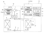
- FIG. 1 is a schematic configuration diagram of an air conditioner 10 including an indoor unit 11 according to the present embodiment.
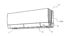
- FIG. 2 is a perspective view of the indoor unit 11 according to the present embodiment.
- the structure of the air conditioning apparatus 10 is demonstrated with reference to FIG.1 and FIG.2.
- the air conditioning target space refers to, for example, a room where the indoor unit 11 is installed.
- the air conditioner 10 includes an indoor unit 11 and an outdoor unit 12.
- the indoor unit 11 and the outdoor unit 12 are connected via a refrigerant pipe P.
- the air conditioner 10 includes a compressor 1, a four-way valve 1 ⁇ / b> B, an outdoor heat exchanger 2, an expansion device 3, and an indoor heat exchanger 4.
- the compressor 1, the four-way valve 1B, the outdoor heat exchanger 2, the expansion device 3, and the indoor heat exchanger 4 are connected by a refrigerant pipe P.
- the indoor unit 11 includes an indoor heat exchanger 4 and a blower fan 5, and the outdoor unit 12 includes a compressor 1, a four-way valve 1 ⁇ / b> B, an outdoor heat exchanger 2, and an expansion device 3.
- the expansion device 3 may be disposed outside the outdoor unit 12 and the indoor unit 11 or may be disposed in the indoor unit 11.
- the air conditioner 10 includes a blower fan 5 attached to the indoor heat exchanger 4.
- the air conditioner 10 also adjusts the direction of the air supplied from the indoor unit 11 to the air-conditioning target space in the left-right direction, the infrared sensor 9 provided in the indoor unit 11, the thermistor 8 provided in the indoor unit 11.
- a vertical wind direction plate 6 that adjusts the direction of the air supplied from the indoor unit 11 to the air-conditioning target space in the vertical direction.
- the air conditioning apparatus 10 is equipped with a control device Cn.
- the control device Cn includes a control device Cn1 provided in the indoor unit 11 and a control device Cn2 provided in the outdoor unit 12.
- the compressor 1 compresses and discharges the refrigerant.
- the compressor 1 has a discharge side and a suction side connected to the four-way valve 1B.
- the four-way valve 1B is a refrigerant flow switching device.
- the four-way valve 1B connects the discharge side of the compressor 1 and the outdoor heat exchanger 2, and connects the suction side of the compressor 1 and the indoor heat exchanger 4;
- the second position where the discharge side and the indoor heat exchanger 4 are connected and the suction side of the compressor 1 and the outdoor heat exchanger 2 are connected can be switched.
- the outdoor heat exchanger 2 has one end connected to the four-way valve 1B and the other end connected to the expansion device 3.
- the outdoor heat exchanger 2 can be composed of, for example, a fin tube heat exchanger.
- the outdoor heat exchanger 2 functions as an evaporator, and when the air conditioner 10 performs the cooling operation, the outdoor heat exchanger 2 functions as a condenser (a radiator). ).
- the expansion device 3 has one end connected to the outdoor heat exchanger 2 and the other end connected to the indoor heat exchanger 4.
- the throttling device 3 can be constituted by, for example, a pressure reducing valve capable of adjusting the throttling amount, or can be constituted by a capillary tube.
- the indoor heat exchanger 4 has one end connected to the expansion device 3 and the other end connected to the four-way valve 1B.
- the indoor heat exchanger 4 can be composed of, for example, a fin tube heat exchanger.
- the indoor heat exchanger 4 functions as a condenser, and when the air conditioner 10 performs the cooling operation, the indoor heat exchanger 4 functions as an evaporator. .
- the blower fan 5 is mounted on the indoor unit 11.
- the indoor unit 11 includes a housing 11A that forms an outer shell, and the blower fan 5 is mounted in the housing 11A.
- the air inlet and the air outlet of the housing 11A are formed.
- the outdoor heat exchanger 2 may be provided with a blower fan.
- the infrared sensor 9 is provided in the housing 11A and detects infrared rays radiated into the air-conditioning target space.
- the infrared sensor 9 is provided on the lower side of the housing 11A. Specifically, the infrared sensor 9 is provided so as to protrude from the lower surface of the housing 11A, and is disposed on one end side in the longitudinal direction of the housing 11A.
- the infrared sensor 9 is rotated by a stepping motor (not shown) so as to scan infrared rays in the air-conditioning target space.
- the detection result (infrared radiation temperature data) of the infrared sensor 9 is output to the control device Cn.
- the thermistor 8 is provided in the housing 11A and detects the temperature of the air-conditioning target space.
- the detection result (room temperature data) of the thermistor 8 is output to the control device Cn.
- the left and right wind direction plates 7 are arranged at the outlet of the housing 11A.
- the left and right wind direction plate 7 is configured by, for example, a plate-like member.
- the left and right wind direction plates 7 are fixed to a shaft (not shown) and rotate left and right as the shaft moves. Thereby, the air conditioning apparatus 10 can adjust the direction of the air which blows off from the blower outlet of the housing
- the up / down wind direction plate 6 is disposed at the outlet of the housing 11 ⁇ / b> A and is attached to the left / right wind direction plate 7.
- the up / down wind direction plate 6 and the left / right wind direction plate 7 are formed of, for example, a plate member.
- the left and right wind direction plates 7 are fixed to a shaft (not shown) and rotate left and right as the shaft moves. Thereby, the air conditioning apparatus 10 can adjust the direction of the air which blows off from the blower outlet of the housing
- the control device Cn has a function of determining whether or not a floor heating device installed under the floor surface of the air-conditioning target space is operating based on the detection result of the infrared sensor 9.
- the control device Cn includes a control device Cn1 provided in the indoor unit 11 and a control device Cn2 provided in the outdoor unit 12.
- the control device Cn1 and the control device Cn2 communicate, and the control device Cn1 and the control device Cn2 cooperate to control various actuators such as the compressor 1.
- the control device Cn1 includes an actuator control unit 15, a storage unit 18, a floor heating determination unit 20, and a timer unit 21.
- the control device Cn2 includes a compressor rotation speed control unit 32 and an indoor temperature adjustment unit 31.
- the floor heating determination unit 20 and the room temperature adjustment unit 31 are also collectively referred to as a determination unit d.
- the actuator controller 15 controls the motors of the up / down wind direction plate 6, the left / right wind direction plate 7, and the blower fan 5 based on the determination result of the determination unit d and the like.
- the storage unit 18 stores data including temperature data that is the detection result of the thermistor 8 and overall thermal image data that is the detection result of the infrared sensor 9.
- the whole thermal image data is acquired by the infrared sensor 9 scanning the air conditioning target space.
- the entire image data includes floor surface thermal image data and wall surface image data. Note that if the wall surface does not enter the scanning range of the infrared sensor 9 and all the objects that enter the scanning range are floor surfaces, the wall image data is not included in the entire image data.
- the entire thermal image data is composed of a plurality of element data.
- the floor surface thermal image data is composed of a plurality of element data
- the wall surface image data is also composed of a plurality of element data.
- the element data is data corresponding to LBS (Least Significant Bit), and is the minimum unit of thermal data acquired by the infrared sensor 9.
- the element data includes coordinate data (x, y) and temperature data (T) corresponding to the coordinate data.
- This element data corresponds to the coordinate data indicating the first coordinate x corresponding to the first direction and the second coordinate y corresponding to the second direction, and the first coordinate x and the second coordinate y.
- the temperature is related to temperature data T indicating the temperature of the floor at the position. That is, the element data can be represented by (x, y, T).
- the floor heating determination unit 20 determines whether or not the floor heating device is operating based on the detection result of the infrared sensor 9.
- the timer unit 21 has a function of measuring various times. For example, the timer 21 measures the time since the air conditioner 10 is started.
- the room temperature adjustment unit 31 instructs the compressor rotation speed control unit 32 to control the compressor 1 based on the determination result of the floor heating determination unit 20 and the detection result of the infrared sensor 9. For example, when the floor heating determination unit 20 determines that the floor heating device is operating, the room temperature adjustment unit 31 compresses the compressor 1 so as to increase, decrease, or maintain the number of rotations. The machine rotation number control unit 32 is instructed.
- the refrigerant discharged from the compressor 1 is supplied to the indoor heat exchanger 4 via the four-way valve 1B. That is, the indoor heat exchanger 4 functions as a condenser.
- the refrigerant supplied to the indoor heat exchanger 4 exchanges heat with the air supplied by the blower fan 5 to be condensed and liquefied.
- the refrigerant flowing out of the indoor heat exchanger 4 is decompressed by the expansion device 3 and becomes a low-temperature and low-pressure gas-liquid two-phase refrigerant.
- the refrigerant that has flowed out of the expansion device 3 is supplied to the outdoor heat exchanger 2. That is, the outdoor heat exchanger 2 functions as an evaporator.
- the refrigerant supplied to the outdoor heat exchanger 2 is evaporated and gasified.
- the refrigerant that has flowed out of the outdoor heat exchanger 2 is returned to the discharge side of the compressor 1 through the four-way valve 1B.
- the refrigerant flow is opposite to that during heating operation.
- FIG. 3 is an explanatory diagram of the infrared sensor 9 of the indoor unit 11 according to this embodiment.
- the infrared sensor 9 is attached to the housing 11 ⁇ / b> A at an angle downward with respect to the floor surface (for example, a depression angle of about 24.5 degrees).
- the infrared sensor 9 has eight light receiving elements (not shown) arranged inside a metallic cylindrical member 9A.
- the eight light receiving elements are arranged in a line in the vertical direction.
- a lens window (not shown) for passing infrared rays through the light receiving element is provided.
- the light distribution viewing angle 9B of each light receiving element is such that the vertical light distribution viewing angle 9B1 is 7 degrees and the horizontal light distribution viewing angle 9B2 is 8 degrees.
- the light distribution viewing angle 9B of each light receiving element showed the thing of 7 degrees of vertical directions and 8 degrees of horizontal directions, it is not limited to 7 degrees of vertical directions and 8 degrees of horizontal directions.
- the number of light receiving elements changes according to the light distribution viewing angle 9B of each light receiving element.
- the product of the vertical light distribution viewing angle 9B1 of each light receiving element and the number of light receiving elements may be made constant.
- the infrared sensor 9 can rotate a predetermined angle range in the left-right direction by the action of a stepping motor (not shown) or the like. That is, the infrared sensor 9 can scan a floor surface and a wall surface in a predetermined range. Here, every time the rotation angle of the stepping motor is 1.6 degrees, the stepping motor stops rotating for a predetermined time (0.1 to 0.2 seconds), and the infrared sensor 9 receives the light from the light receiving element. The thermal image data of the surface and the wall surface is acquired.
- the infrared sensor 9 can acquire the entire thermal image data by repeating the operation of rotating the stepping motor by 1.6 degrees and the operation of acquiring the thermal image data from the light receiving element.
- the operation is as follows. For example, when the stepping motor (infrared sensor 9) starts rotating from the lower limit value of the rotation angle, the rotation angle increases, and when the rotation angle reaches the upper limit value, the rotation angle of the stepping motor (infrared sensor 9) again. Decreases from the upper limit to the lower limit.
- the infrared sensor 9 combines the thermal image data acquired for each rotation angle of the stepping motor to acquire the entire thermal image data.
- the infrared sensor 9 scans from the lower limit value to the upper limit value of the rotation angle of the stepping motor, the infrared sensor 9 acquires 94 thermal image data.
- the control apparatus Cn produces the whole thermal image data based on 94 thermal image data.
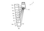
- FIG. 4 is a diagram showing a vertical light distribution viewing angle of the infrared sensor 9 of the indoor unit 11 according to the present embodiment.
- FIG. 4 shows a vertical light distribution viewing angle in a state where the indoor unit 11 is installed at a height of 1800 mm from the floor surface of the room.
- the light distribution viewing angle 9B1 in the vertical direction of one light receiving element is 7 degrees.
- FIG. 4 shows a total light distribution viewing angle 9B3 that is a vertical light distribution viewing angle of all the light receiving elements.
- An angle range that does not fall within the total light distribution viewing angle 9B3 of the infrared sensor 9 is an angle range 9B4.
- the angle range 9B4 is an angle between the wall on which the indoor unit 11 is attached and the lower limit angle of the total light distribution viewing angle 9B3.
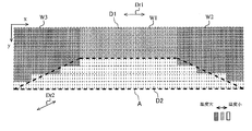
- FIG. 5 is the entire thermal image data including the floor surface A and the wall W1, the wall W2, and the wall W3 of the air conditioning target space (indoor).
- the floor surface A is indicated by a dotted trapezoidal portion in FIG. Further, the floor surface A is formed so as to spread in the first direction Dr1 and the second direction Dr2.
- the floor surface A, the first direction Dr1, and the second direction Dr2 are concepts in real space.
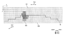
- FIG. 6 is overall thermal image data including a user who is present in the air-conditioning target space (indoor). Further, on the entire thermal image data D1, the floor surface A corresponds to the range indicated by the region B as shown in FIG. On the whole thermal image data, the first direction Dr1 in the real space corresponds to the direction of the first coordinate x, and the second direction Dr2 in the real space corresponds to the direction of the second coordinate y. . Further, in the overall thermal image data, when the user is present in the air-conditioning target space, the temperature in the range where the user exists increases as shown in FIG. In FIG. 6, the data of the fixed range of the first coordinate and the fixed range of the second coordinate indicate that the temperature is rising. In FIG. 6, the data of the fixed range of the first coordinates and the fixed range of the second coordinates are shown as thermal image data D3.
- the control device Cn can calculate a range corresponding to the floor surface A using the acquired entire thermal image data D1. That is, the control device Cn can calculate the range of the region B based on the entire thermal image data D1.
- a known means for example, JP 2010-91253 A
- JP 2010-91253 A can be employed.
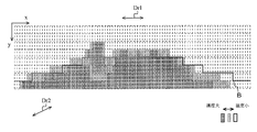
- FIG. 7 shows the entire thermal image data D1 when the floor heating device is operating in the operation mode in which the entire floor surface A is heated.
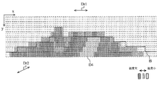
- FIG. 8 shows the entire thermal image data D1 when furniture is arranged on the floor surface A of the air-conditioning target space (indoor) and the floor heating equipment is in operation.
- FIG. 7 shows that the floor heating device is operating and the entire floor surface A (the entire region B) is warmed. However, even if the entire floor surface A is warm, if furniture such as a sofa and a table is arranged in the air-conditioning target space, a part of infrared rays emitted from the floor surface A is blocked by the furniture.
- the thermal image data D4 in the fixed range of the first coordinate and the fixed range of the second coordinate is compared with the data in the peripheral range, it indicates that the temperature is lowered.
- data of the fixed range of the first coordinates and the fixed range of the second coordinates are shown as thermal image data D4.
- the thermal image data indicating a high temperature is divided due to the presence of the thermal image data D4.
- the thermal image data is divided, the determination accuracy of the operation of the floor heating device is lowered. That is, although the floor heating apparatus is actually operating, the range showing the high temperature is divided and shortened, so that it may be determined that the floor heating apparatus is not operating. Such an erroneous determination can be avoided in the indoor unit 11 according to the present embodiment.
- the control device Cn has a function of acquiring the entire thermal image data D1 indicating the temperature distribution within the infrared detection range of the infrared sensor 9 based on the detection result of the infrared sensor 9.
- the control device Cn generates the floor surface thermal image data D2 indicating the temperature distribution in the first direction Dr1 of the floor surface A and the second direction Dr2 that intersects the first direction Dr1 in the entire thermal image data D1. Based on this, it is determined whether or not the heating device is operating.
- the control device Cn when the ratio of the element data having a temperature higher than the first temperature threshold among the predetermined number of element data is equal to or higher than the predetermined ratio, Determine that the device is operating.
- the determination unit d of the control device Cn is not the temperature distribution in the first direction Dr1 (first coordinate x direction) or the second direction Dr2 (second coordinate y direction), but the first direction
- the operation of the floor heating appliance is determined using the temperature distributions in both Dr1 (first coordinate x direction) and second direction Dr2 (second coordinate y direction). Therefore, the determination accuracy of the operation of the floor heating apparatus can be improved.
- the effect of improving the determination accuracy is particularly great when furniture is arranged in the air-conditioned space as shown in FIG.
- the control device Cn determines that the floor heating equipment is operating as follows.
- the control device Cn determines that the ratio of element data having a temperature higher than a first temperature threshold (for example, 25 degrees) in the entire element data is equal to or higher than the first ratio (for example, 60%). Is determined to be driving.
- the total number of element data is 270.
- the control device Cn determines that the floor heating equipment is operating as follows.
- the total number of element data is 270, which is the same as in FIG.
- the number of pieces of element data that are equal to or higher than the first temperature threshold is reduced to 163 due to the presence of furniture.
- 163/270 about 60.3%, which is above the first ratio. Therefore, the determination unit d of the control device Cn can determine that the floor heating equipment is operating. That is, the control device Cn can determine that the floor heating apparatus is operating even if the thermal image data indicating the high temperature is divided due to the presence of the thermal image data D4.
- FIG. 9 shows the entire thermal image data D1 when the floor heating device is operating in the operation mode in which half of the entire floor surface A is heated.
- Some floor heating devices have not only a mode in which the entire floor surface A is heated, but also a mode in which a half area of the floor surface A and a 3/4 area of the floor surface A are heated. Even in such a case, the control device Cn can determine whether or not the floor heating apparatus is operating with high accuracy.
- the control device Cn has a first temperature threshold value (for example, 35 degrees) among element data belonging to a second range in which the first coordinate x is continuous and the second coordinate y is continuous.
- the determination unit d of the indoor unit 11 can determine that the floor heating device is operating even in a mode in which a half region of the floor surface A is heated.
- the first ratio and the second ratio are described as being equal, but they may be different.
- the control device Cn determines that the floor heating equipment is operating as follows.
- the number of element data belonging to the first range r1 where the first coordinate x is continuous and the second range r2 where the second coordinate y is continuous is 135.
- a first range r1 and a second range r2 are set assuming a mode in which half of the floor surface A is heated.
- the control device Cn includes a plurality of variations of the first range r1 and the second range r2, assuming other floor heating appliance modes.
- the control device Cn uses the first temperature threshold, but the present invention is not limited to this.
- the control device Cn may be set with a second temperature threshold (for example, 35 degrees) that is larger than the first temperature threshold. That is, the determination unit d of the control device Cn has an element whose temperature is higher than the first temperature threshold and lower than the second threshold higher than the first temperature threshold among the entire element data.
- a first ratio for example, 60%
- the method for determining the first temperature threshold and the second temperature threshold has been described as roughly 25 degrees and 35 degrees, but is not limited thereto, and is determined based on the detected temperature of the thermistor 8. Also good. That is, the control device Cn may set the first temperature threshold value to be larger than the detected temperature of the thermistor 8 and set the second temperature threshold value to be larger than the first temperature threshold value.
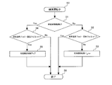
- FIG. 10 is a control flowchart 1 of the indoor unit 11 according to the present embodiment.
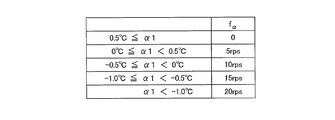
- FIG. 11 is a table showing the reduction amount f ⁇ of the rotation speed of the compressor 1 for each ⁇ 1 in the flowchart shown in FIG.
- the control device Cn determines that the floor heating equipment is not operating during the heating operation
- the detection result of the infrared sensor 9 is added to the set temperature of the air-conditioning target space and the detection temperature of the temperature sensor (thermistor 8).
- the number of rotations of the compressor 1 is controlled based on the first sensed temperature.
- the control device Cn sets the first temperature correction value (correction described later) to the set temperature and the temperature detected by the temperature sensor (thermistor 8).
- the rotational speed of the compressor 1 is controlled based on the second sensory temperature obtained by subtracting the value Co2). Further, the control device Cn increases the rotation speed of the compressor 1 when the difference between the set temperature and the second sensible temperature is equal to or greater than a predetermined value.
- Step S0 The control device Cn performs the heating operation.
- Step S1 The control device Cn determines whether or not the floor heating equipment is operating. (1) If it is determined that the floor heating device is not operating, the process proceeds to step S2. In the case of shifting to step S2, control for increasing the rotational speed of the compressor 1 is not performed, and control for maintaining the rotational speed of the compressor 1 (step S6) or decreasing (step S3) is performed. This means that the floor heating device is not in operation, and is corrected by the detection result of the infrared sensor 9 from the room temperature. In other words, if the floor surface is sufficiently warm when the floor heating equipment is not in operation, even if the number of rotations of the compressor 1 is reduced, the possibility of giving the user a cool air feeling is low, and the room temperature is also low.
- step S4 If it is determined that the floor heating device is operating, the process proceeds to step S4. In the case of shifting to step S4, the control for reducing the rotational speed of the compressor 1 is not performed, and the control for maintaining the rotational speed of the compressor 1 (step S6) or increasing (step S5) is performed.
- the floor heating device is in operation, and if the room temperature is corrected by the detection result of the infrared sensor 9, there is a possibility of giving the user a feeling of cold air.
- the infrared sensor 9 corrects the room temperature based on the temperature of the floor heated by the floor heating. Become. That is, it is determined that the perceived temperature is high and control for reducing the rotational speed of the compressor 1 may be executed.
- control for reducing the rotational speed of the compressor 1 is executed even though the room temperature is not so high in practice, there is a possibility that the user will be given a cold wind feeling.
- control for reducing the rotational speed of the compressor 1 is not performed, and control for maintaining or increasing the rotational speed of the compressor 1 is performed.
- Step S2 The control device Cn determines whether or not a value obtained by subtracting the detected temperature of the thermistor 8 from the set temperature of the air-conditioning target space set by a remote controller or the like is ⁇ 1 or more. If it is ⁇ 1 or more, the process proceeds to step S6. If not ⁇ 1 or more, the process proceeds to step S3.
- Step S3 The control device Cn reduces the rotational speed of the compressor 1.
- the reduction amount f ⁇ is changed according to the value of ⁇ 1, as shown in FIG. For example, when the set temperature is 24 degrees and ⁇ 1 is 0.5 degrees, when the room temperature is 23.5 degrees or more, the process proceeds from step S2 to step S3, and the compressor 1 The number of revolutions will be reduced.
- Step S4 The control device Cn determines whether or not a value obtained by subtracting the detected temperature of the thermistor 8 from the set temperature of the air-conditioning target space set by a remote controller or the like is ⁇ 2 or more. If it is ⁇ 2 or more, the process proceeds to step S5. If not ⁇ 2 or more, the process proceeds to step S6.
- Step S5 The control device Cn increases the rotational speed of the compressor 1.
- the increase amount may be a constant, or may be changed according to the difference between the set temperature and room temperature 9. That is, the larger the difference is, the larger the amount of increase in the rotational speed of the compressor 1 may be.
- step S2 the following equation is used.
- Setting temperature Tset ⁇ room temperature Ta ⁇ ⁇ 1 (Formula 1)
- ⁇ 1 C1 (constant)
- the correction value Co1 is a positive value, and increases as the floor surface is warmer (the radiation temperature is higher). Therefore, ⁇ 1 is a variable.
- Equation 1 can be rewritten as follows.
- the numerical value of the room temperature Ta-correction value Co1 is a numerical value corresponding to the first body temperature.
- step S4 the following equation is used. Setting temperature Tset ⁇ room temperature Ta ⁇ ⁇ 2 (Formula 2)
- ⁇ 2 C2 (constant) + correction value Co2.
- the correction value Co2 is a positive value and is not determined based on the floor surface temperature. Equation 2 can be rewritten as follows. Set temperature Tset ⁇ (room temperature Ta + correction value Co2) ⁇ C2 (constant)
- the room temperature Ta + correction value Co2 is a numerical value corresponding to the second body temperature. The reason why the correction value Co2 is provided is to avoid erroneously detecting that the room is warm when the floor heating apparatus is in operation.
- control device Cn erroneously detects that the room is warmed by the high temperature of the floor when the infrared sensor 9 scans the room. Then, in reality, the room is not warmed up so much and the rotational speed of the compressor 1 should not be lowered, but control may be shifted to lowering the rotational speed of the compressor 1.
- step S1 to step S4 the control device Cn of the indoor unit 11 according to the present embodiment performs the calculation of the above (formula 2) to satisfy this.
- the rotational speed of the compressor 1 is increased (step S5), and even if not satisfied, the rotational speed of the compressor 1 is maintained (step S6 in FIG. 10).
- the amount of increase in the rotation speed of the compressor 1 is preferably set larger as the difference between the set temperature and the second body temperature is larger.
- step S1 to step S2 when it determines with the control apparatus Cn of the indoor unit 11 which concerns on this Embodiment not operating the floor heating apparatus (step S1 to step S2), it performs the calculation of said (Formula 1), and satisfy
- the reduction amount f ⁇ of the rotation speed of the compressor 1 is preferably set to be larger as ⁇ 1 is smaller based on the relationship shown in FIG.
- FIG. 12 is a control flowchart 2 of the indoor unit 11 according to the present embodiment.
- FIG. 13 is a table showing the amount of reduction in the rotational speed of the compressor 1 for each beta in the flowchart shown in FIG.
- the difference between the temperature of the floor surface and the temperature detected by the temperature sensor (thermistor 8) is equal to or less than the first temperature difference. If so, control is performed so that the rotational speed of the compressor 1 is reduced.
- the difference between the temperature of the floor surface and the temperature detected by the temperature sensor (thermistor 8) is equal to or less than the first temperature difference. Even if it becomes, the rotation speed of the compressor 1 is maintained or increased without decreasing the rotation speed of the compressor 1.
- Step S10 The control device Cn performs the heating operation.
- Step S11 The control device Cn determines whether or not the floor heating equipment is operating.
- Step S12 The control device Cn determines whether or not a value (first temperature difference) obtained by subtracting the floor surface temperature Tfav obtained from the detection result of the infrared sensor 9 from the detection temperature of the thermistor 8 is equal to or greater than ⁇ 1.
- the floor surface temperature Tfav can be obtained by, for example, averaging temperature data included in element data in an integrated range of the infrared sensor 9. If ⁇ 1 or more, the process proceeds to step S16. If not ⁇ 1 or more, the process proceeds to step S13.
- Step S13 The control device Cn reduces the rotational speed of the compressor 1.
- the reduction amount f ⁇ is changed according to the value of ⁇ 1, as shown in FIG. For example, when the room temperature is 23.5 degrees and ⁇ 1 is 0.5 degrees, the process proceeds from step S12 to step S13 when the floor surface temperature Tfav is 23.0 degrees or more. Therefore, the rotational speed of the compressor 1 is reduced.
- Step S14 The control device Cn determines whether or not a value (second temperature difference) obtained by subtracting the floor surface temperature Tfav obtained from the detection result of the infrared sensor 9 from the detection temperature of the thermistor 8 is equal to or greater than ⁇ 2.
- the second temperature difference in step S14 is smaller than the first temperature difference in step S12. If ⁇ 2 or more, the process proceeds to step S15. If not ⁇ 2 or more, the process proceeds to step S16. Therefore, even if the difference between the floor surface temperature Tfav and the temperature detected by the temperature sensor (thermistor 8) is equal to or less than the first temperature difference, the rotation of the compressor 1 can be performed without reducing the rotation speed of the compressor 1. The number will be maintained or increased.
- Step S15 The control device Cn increases the rotational speed of the compressor 1.
- the increase amount may be a constant, or may be changed according to the difference between the detected temperature of the thermistor 8 and the floor temperature Tfav obtained from the detection result of the infrared sensor 9. That is, the larger the difference is, the larger the amount of increase in the rotational speed of the compressor 1 may be.
- ⁇ 1 and ⁇ 2 described above are values predetermined for the control device Cn.
- ⁇ 1 and ⁇ 2 may be variables or constants as shown in FIG.
- the condition in step S4 in FIG. 10 may include a condition that the specified time has elapsed after the air conditioner 10 is activated. That is, if the condition of step S4 or the condition that the specified time has elapsed since the start of the air conditioner 10 is satisfied, the process proceeds to step S5, and if both conditions are not satisfied, the step is performed. The process proceeds to S6. Further, even in the condition of step S14 in FIG. 12, there may be a condition that the specified time has elapsed after the air conditioner 10 is activated. That is, if the condition of step S14 or the condition that the specified time has elapsed since the start of the air conditioner 10 is satisfied, the process proceeds to step S15, and if both conditions are not satisfied, the step is performed.
- step S4 and step S14 are relaxed to facilitate the control to increase the rotational speed of the compressor 1. Thereby, it can avoid more reliably that a user's comfort reduces.
- the indoor unit 11 of the air-conditioning apparatus 10 Based on the detection result of the infrared sensor 9, the indoor unit 11 of the air-conditioning apparatus 10 according to the present embodiment converts the entire thermal image data D1 indicating the temperature distribution within the infrared detection range of the infrared sensor 9 into the entire thermal image data D1.
- the heating device is operated based on the floor surface thermal image data D2 indicating the temperature distribution in the first direction Dr1 and the second direction Dr2 intersecting the first direction Dr1. It is determined whether or not. For this reason, it is possible to improve the determination accuracy of whether or not the floor heating apparatus is operating.
- the indoor unit 11 of the air-conditioning apparatus 10 reduces the rotational speed of the compressor 1 in a situation where the rotational speed of the compressor 1 should not be decreased even when the floor heating equipment is operating. Can be avoided, and the user's comfort can be prevented from being reduced.
- the indoor unit 11 of the air conditioning apparatus 10 can improve the detection accuracy of the operation of the floor heating device, it becomes easier to execute the air conditioning control according to the operation of the floor heating device, and the consumption An increase in power can be suppressed.
- the place where the indoor unit 11 is installed and the air-conditioning target space are described as the same space, but the present invention is not limited to this.
- the air conditioner 10 may be configured such that the indoor unit 11 is installed outside the air-conditioning target space, and the air outlet of the indoor unit 11 communicates with the air-conditioning target space via a duct.
- the infrared sensor 9 may be separated from the casing 11A of the indoor unit 11 and the infrared sensor 9 may be installed in the air conditioning target space.
- the control target is the compressor 1, but the control target may be the blower fan 5. That is, if the control device Cn determines that the floor heating device is not operating during the heating operation, the detection result of the infrared sensor 9 is set to the set temperature of the air-conditioning target space and the detected temperature of the temperature sensor (thermistor 8). The number of rotations of the blower fan 5 is controlled on the basis of the first sensory temperature in consideration of the above. In addition, when the control device Cn determines that the floor heating device is operating during the heating operation, the control device Cn sets the first temperature correction value (correction value Co2) to the set temperature and the temperature detected by the temperature sensor (thermistor 8).
- the first temperature correction value correction value
- the number of rotations of the blower fan 5 is controlled based on the second sensory temperature obtained by subtracting). Furthermore, the control device Cn increases the rotational speed of the blower fan 5 when the difference between the set temperature and the second sensible temperature is equal to or greater than a predetermined value. Even with these configurations, the same effects as those described with reference to FIGS. 10 and 11 can be obtained.
- the control target is the compressor 1 in FIGS. 12 and 13
- the control target may be the blower fan 5. That is, if the control device Cn determines that the floor heating device is not operating during the heating operation, the difference between the temperature of the floor surface and the temperature detected by the temperature sensor (thermistor 8) is the first temperature difference. When it is below, it controls so that the rotation speed of the ventilation fan 5 becomes small. In addition, when the control device Cn determines that the floor heating apparatus is operating during the heating operation, the difference between the temperature of the floor surface and the temperature detected by the temperature sensor (thermistor 8) is equal to or less than the first temperature difference. Even if it becomes, without rotating the rotation speed of the ventilation fan 5, the rotation speed of the ventilation fan 5 is maintained or increased. Even with these configurations, the same effects as those described with reference to FIGS. 12 and 13 can be obtained.
Landscapes
- Engineering & Computer Science (AREA)
- Chemical & Material Sciences (AREA)
- Combustion & Propulsion (AREA)
- Mechanical Engineering (AREA)
- General Engineering & Computer Science (AREA)
- Physics & Mathematics (AREA)
- Thermal Sciences (AREA)
- Fluid Mechanics (AREA)
- General Physics & Mathematics (AREA)
- Spectroscopy & Molecular Physics (AREA)
- Air Conditioning Control Device (AREA)
Abstract
La présente invention comprend une enveloppe, un capteur infrarouge disposé dans l'enveloppe et destiné à détecter des rayons infrarouges émis vers un espace à climatiser, et un dispositif de commande destiné à déterminer, sur la base du résultat de détection du capteur infrarouge, si un dispositif de chauffage par le sol installé en dessous d'une surface de sol dans l'espace à climatiser est en fonctionnement, le dispositif de commande permettant d'effectuer une conversion en données d'images thermiques globales, d'indiquer la distribution de température dans une plage de détection de rayons infrarouges du capteur infrarouge, sur la base du résultat de détection du capteur infrarouge, et de déterminer si le dispositif de chauffage est en fonctionnement sur la base des données d'images thermiques de la surface de sol parmi les données d'images thermiques globales, lesdites données d'images thermiques de la surface de sol indiquant la distribution de température dans une première direction de la surface de sol et dans une seconde direction croisant la première direction.
Priority Applications (7)
| Application Number | Priority Date | Filing Date | Title |
|---|---|---|---|
| PCT/JP2016/061125 WO2017175305A1 (fr) | 2016-04-05 | 2016-04-05 | Unité intérieure pour climatiseur |
| CN201680083421.2A CN108885021B (zh) | 2016-04-05 | 2016-12-08 | 空调装置的室内机 |
| RU2018131226A RU2704922C1 (ru) | 2016-04-05 | 2016-12-08 | Устанавливаемый внутри помещения блок агрегата для кондиционирования воздуха |
| PCT/JP2016/086615 WO2017175419A1 (fr) | 2016-04-05 | 2016-12-08 | Unité intérieure pour climatiseur |
| JP2018510225A JP6628865B2 (ja) | 2016-04-05 | 2016-12-08 | 空気調和装置の室内機 |
| EP16897971.4A EP3441688B1 (fr) | 2016-04-05 | 2016-12-08 | Unité intérieure de climatiseur |
| US16/071,618 US10794610B2 (en) | 2016-04-05 | 2016-12-08 | Indoor unit of air-conditioning apparatus having an infrared sensor |
Applications Claiming Priority (1)
| Application Number | Priority Date | Filing Date | Title |
|---|---|---|---|
| PCT/JP2016/061125 WO2017175305A1 (fr) | 2016-04-05 | 2016-04-05 | Unité intérieure pour climatiseur |
Publications (1)
| Publication Number | Publication Date |
|---|---|
| WO2017175305A1 true WO2017175305A1 (fr) | 2017-10-12 |
Family
ID=60000327
Family Applications (2)
| Application Number | Title | Priority Date | Filing Date |
|---|---|---|---|
| PCT/JP2016/061125 Ceased WO2017175305A1 (fr) | 2016-04-05 | 2016-04-05 | Unité intérieure pour climatiseur |
| PCT/JP2016/086615 Ceased WO2017175419A1 (fr) | 2016-04-05 | 2016-12-08 | Unité intérieure pour climatiseur |
Family Applications After (1)
| Application Number | Title | Priority Date | Filing Date |
|---|---|---|---|
| PCT/JP2016/086615 Ceased WO2017175419A1 (fr) | 2016-04-05 | 2016-12-08 | Unité intérieure pour climatiseur |
Country Status (6)
| Country | Link |
|---|---|
| US (1) | US10794610B2 (fr) |
| EP (1) | EP3441688B1 (fr) |
| JP (1) | JP6628865B2 (fr) |
| CN (1) | CN108885021B (fr) |
| RU (1) | RU2704922C1 (fr) |
| WO (2) | WO2017175305A1 (fr) |
Cited By (7)
| Publication number | Priority date | Publication date | Assignee | Title |
|---|---|---|---|---|
| CN108954709A (zh) * | 2018-06-29 | 2018-12-07 | 广东美的制冷设备有限公司 | 空气调节设备的控制方法、装置和空气调节设备 |
| CN110906493A (zh) * | 2018-09-14 | 2020-03-24 | 青岛海尔空调器有限总公司 | 一种温冷感投影展示控制方法及装置 |
| CN110906491A (zh) * | 2018-09-14 | 2020-03-24 | 青岛海尔空调器有限总公司 | 一种温冷感展示控制方法及装置 |
| CN110906492A (zh) * | 2018-09-14 | 2020-03-24 | 青岛海尔空调器有限总公司 | 一种温冷感地面展示控制方法及装置 |
| CN111351186A (zh) * | 2020-03-16 | 2020-06-30 | 广东美的制冷设备有限公司 | 空调器的运行方法、装置、空调器和计算机可读存储介质 |
| CN112212483A (zh) * | 2020-10-16 | 2021-01-12 | 珠海格力节能环保制冷技术研究中心有限公司 | 基于红外热成像的空调控制方法、装置及空调机组 |
| CN115077036A (zh) * | 2022-05-18 | 2022-09-20 | 重庆海尔空调器有限公司 | 一种空调风机转速调节方法、系统及存储介质 |
Families Citing this family (6)
| Publication number | Priority date | Publication date | Assignee | Title |
|---|---|---|---|---|
| US11185235B2 (en) * | 2017-03-27 | 2021-11-30 | Panasonic Intellectual Property Management Co., Ltd. | Information processing method, information processing device, and recording medium |
| EP4123236B1 (fr) * | 2017-04-07 | 2023-09-13 | Mitsubishi Electric Corporation | Climatiseur |
| KR102756470B1 (ko) * | 2019-01-02 | 2025-01-20 | 엘지이노텍 주식회사 | 사육장 환경 관리 장치 |
| DE112019007651T5 (de) * | 2019-08-23 | 2022-07-07 | Mitsubishi Electric Corporation | Klimatisierungssystem |
| WO2021155366A1 (fr) | 2020-01-31 | 2021-08-05 | Objectvideo Labs, Llc | Régulation de température basée sur l'imagerie thermique |
| JP7609678B2 (ja) * | 2021-03-29 | 2025-01-07 | アズビル株式会社 | 温度測定装置 |
Citations (9)
| Publication number | Priority date | Publication date | Assignee | Title |
|---|---|---|---|---|
| JPH01196445A (ja) * | 1988-02-01 | 1989-08-08 | Mitsubishi Electric Corp | 空気調和機 |
| JPH05312381A (ja) * | 1992-05-06 | 1993-11-22 | Res Dev Corp Of Japan | 空気調和システム |
| JPH06160507A (ja) * | 1992-09-24 | 1994-06-07 | Matsushita Electric Ind Co Ltd | 人存在状況判定装置 |
| JPH11153328A (ja) * | 1997-11-25 | 1999-06-08 | Sanyo Electric Co Ltd | 床暖房装置の試験方法及び空気調和機 |
| JP2000055445A (ja) * | 1998-08-05 | 2000-02-25 | Daikin Ind Ltd | 空気調和機の制御方法 |
| JP2000130823A (ja) * | 1998-10-26 | 2000-05-12 | Noritz Corp | 室内暖房装置 |
| JP2004028450A (ja) * | 2002-06-26 | 2004-01-29 | Mitsubishi Electric Corp | 空気調和装置 |
| US20060065754A1 (en) * | 2004-09-24 | 2006-03-30 | Danfoss A/S | Room heating system |
| JP2006336915A (ja) * | 2005-05-31 | 2006-12-14 | Tokyo Electric Power Co Inc:The | 冷房設備および快適空間設備 |
Family Cites Families (13)
| Publication number | Priority date | Publication date | Assignee | Title |
|---|---|---|---|---|
| CN1056225C (zh) * | 1992-03-07 | 2000-09-06 | 三星电子株式会社 | 空调系统 |
| JPH0771785A (ja) * | 1993-08-31 | 1995-03-17 | Sanyo Electric Co Ltd | 空気調和機 |
| JP3225993B2 (ja) | 1994-04-20 | 2001-11-05 | 株式会社日立製作所 | 人体検出装置及びこれを用いた空調装置 |
| CN1258662C (zh) * | 2000-10-04 | 2006-06-07 | 夏普公司 | 空调机及温度检测装置 |
| JP2003322388A (ja) | 2002-05-02 | 2003-11-14 | Toshiba Kyaria Kk | 空気調和機 |
| JP2004286412A (ja) | 2003-03-25 | 2004-10-14 | Mitsubishi Electric Corp | 空気調和機能付きヒートポンプ式温水床暖房装置 |
| JP2005147614A (ja) * | 2003-11-19 | 2005-06-09 | Matsushita Electric Ind Co Ltd | 空気調和機 |
| JP5111445B2 (ja) * | 2008-09-10 | 2013-01-09 | 三菱電機株式会社 | 空気調和機 |
| JP5289392B2 (ja) * | 2010-07-16 | 2013-09-11 | 三菱電機株式会社 | 空気調和機 |
| JP5528531B1 (ja) * | 2012-12-25 | 2014-06-25 | 三菱電機株式会社 | 制御システム、制御方法及びプログラム |
| JP6072561B2 (ja) * | 2013-02-20 | 2017-02-01 | 三菱電機株式会社 | 空気調和システム |
| CN104019494B (zh) * | 2013-02-28 | 2018-08-21 | 大金工业株式会社 | 空调机室内机 |
| JP6046579B2 (ja) | 2013-09-09 | 2016-12-21 | ジョンソンコントロールズ ヒタチ エア コンディショニング テクノロジー(ホンコン)リミテッド | 空気調和機 |
-
2016
- 2016-04-05 WO PCT/JP2016/061125 patent/WO2017175305A1/fr not_active Ceased
- 2016-12-08 CN CN201680083421.2A patent/CN108885021B/zh not_active Expired - Fee Related
- 2016-12-08 WO PCT/JP2016/086615 patent/WO2017175419A1/fr not_active Ceased
- 2016-12-08 RU RU2018131226A patent/RU2704922C1/ru not_active IP Right Cessation
- 2016-12-08 US US16/071,618 patent/US10794610B2/en not_active Expired - Fee Related
- 2016-12-08 JP JP2018510225A patent/JP6628865B2/ja not_active Expired - Fee Related
- 2016-12-08 EP EP16897971.4A patent/EP3441688B1/fr active Active
Patent Citations (9)
| Publication number | Priority date | Publication date | Assignee | Title |
|---|---|---|---|---|
| JPH01196445A (ja) * | 1988-02-01 | 1989-08-08 | Mitsubishi Electric Corp | 空気調和機 |
| JPH05312381A (ja) * | 1992-05-06 | 1993-11-22 | Res Dev Corp Of Japan | 空気調和システム |
| JPH06160507A (ja) * | 1992-09-24 | 1994-06-07 | Matsushita Electric Ind Co Ltd | 人存在状況判定装置 |
| JPH11153328A (ja) * | 1997-11-25 | 1999-06-08 | Sanyo Electric Co Ltd | 床暖房装置の試験方法及び空気調和機 |
| JP2000055445A (ja) * | 1998-08-05 | 2000-02-25 | Daikin Ind Ltd | 空気調和機の制御方法 |
| JP2000130823A (ja) * | 1998-10-26 | 2000-05-12 | Noritz Corp | 室内暖房装置 |
| JP2004028450A (ja) * | 2002-06-26 | 2004-01-29 | Mitsubishi Electric Corp | 空気調和装置 |
| US20060065754A1 (en) * | 2004-09-24 | 2006-03-30 | Danfoss A/S | Room heating system |
| JP2006336915A (ja) * | 2005-05-31 | 2006-12-14 | Tokyo Electric Power Co Inc:The | 冷房設備および快適空間設備 |
Cited By (11)
| Publication number | Priority date | Publication date | Assignee | Title |
|---|---|---|---|---|
| CN108954709A (zh) * | 2018-06-29 | 2018-12-07 | 广东美的制冷设备有限公司 | 空气调节设备的控制方法、装置和空气调节设备 |
| WO2020000554A1 (fr) * | 2018-06-29 | 2020-01-02 | 广东美的制冷设备有限公司 | Procédé et dispositif de commande pour appareil de climatisation et appareil de climatisation |
| CN110906493A (zh) * | 2018-09-14 | 2020-03-24 | 青岛海尔空调器有限总公司 | 一种温冷感投影展示控制方法及装置 |
| CN110906491A (zh) * | 2018-09-14 | 2020-03-24 | 青岛海尔空调器有限总公司 | 一种温冷感展示控制方法及装置 |
| CN110906492A (zh) * | 2018-09-14 | 2020-03-24 | 青岛海尔空调器有限总公司 | 一种温冷感地面展示控制方法及装置 |
| CN110906491B (zh) * | 2018-09-14 | 2022-04-15 | 青岛海尔空调器有限总公司 | 一种温冷感展示控制方法及装置 |
| CN110906493B (zh) * | 2018-09-14 | 2022-04-15 | 青岛海尔空调器有限总公司 | 一种温冷感投影展示控制方法及装置 |
| CN110906492B (zh) * | 2018-09-14 | 2022-04-19 | 青岛海尔空调器有限总公司 | 一种温冷感地面展示控制方法及装置 |
| CN111351186A (zh) * | 2020-03-16 | 2020-06-30 | 广东美的制冷设备有限公司 | 空调器的运行方法、装置、空调器和计算机可读存储介质 |
| CN112212483A (zh) * | 2020-10-16 | 2021-01-12 | 珠海格力节能环保制冷技术研究中心有限公司 | 基于红外热成像的空调控制方法、装置及空调机组 |
| CN115077036A (zh) * | 2022-05-18 | 2022-09-20 | 重庆海尔空调器有限公司 | 一种空调风机转速调节方法、系统及存储介质 |
Also Published As
| Publication number | Publication date |
|---|---|
| CN108885021B (zh) | 2020-06-12 |
| JP6628865B2 (ja) | 2020-01-15 |
| EP3441688B1 (fr) | 2020-01-29 |
| JPWO2017175419A1 (ja) | 2018-11-01 |
| WO2017175419A1 (fr) | 2017-10-12 |
| EP3441688A4 (fr) | 2019-04-24 |
| CN108885021A (zh) | 2018-11-23 |
| US10794610B2 (en) | 2020-10-06 |
| RU2704922C1 (ru) | 2019-10-31 |
| US20190032950A1 (en) | 2019-01-31 |
| EP3441688A1 (fr) | 2019-02-13 |
Similar Documents
| Publication | Publication Date | Title |
|---|---|---|
| WO2017175305A1 (fr) | Unité intérieure pour climatiseur | |
| JP6242300B2 (ja) | 空気調和装置の室内機及び空気調和装置 | |
| JP5585556B2 (ja) | 空気調和機 | |
| JP6906311B2 (ja) | 空気調和装置 | |
| JP6242309B2 (ja) | 空気調和機 | |
| GB2516336A (en) | Air-conditioning apparatus | |
| JP5507231B2 (ja) | 空気調和機 | |
| JP6956594B2 (ja) | 空気調和装置 | |
| JP6072561B2 (ja) | 空気調和システム | |
| WO2018150535A1 (fr) | Unité intérieure et dispositif de climatisation | |
| JP2016038135A (ja) | 空気調和機 | |
| JP6607267B2 (ja) | 空気調和装置 | |
| AU2004286118A1 (en) | Air conditioner and control method thereof | |
| JP6625222B2 (ja) | 空気調和機の室内機 | |
| JPH0650595A (ja) | 空気調和装置 | |
| JP2004076974A (ja) | 空気調和機および空気調和機の制御方法 | |
| JP2011153725A (ja) | 空気調和装置の天井設置型室内ユニット | |
| JP4478082B2 (ja) | 空気調和機の制御方法 | |
| JP6851483B2 (ja) | 空気調和機 | |
| JP6562094B2 (ja) | 空気調和装置 | |
| US10837670B2 (en) | Air-conditioning apparatus | |
| JP2019138504A (ja) | 空気調和装置 | |
| JP5586542B2 (ja) | 空気調和システム | |
| JP6562139B2 (ja) | 冷凍装置 | |
| JP4178097B2 (ja) | 空気調和機 |
Legal Events
| Date | Code | Title | Description |
|---|---|---|---|
| NENP | Non-entry into the national phase |
Ref country code: DE |
|
| 121 | Ep: the epo has been informed by wipo that ep was designated in this application |
Ref document number: 16897864 Country of ref document: EP Kind code of ref document: A1 |
|
| 122 | Ep: pct application non-entry in european phase |
Ref document number: 16897864 Country of ref document: EP Kind code of ref document: A1 |
|
| NENP | Non-entry into the national phase |
Ref country code: JP |