WO2017175336A1 - Interrupteur - Google Patents
Interrupteur Download PDFInfo
- Publication number
- WO2017175336A1 WO2017175336A1 PCT/JP2016/061270 JP2016061270W WO2017175336A1 WO 2017175336 A1 WO2017175336 A1 WO 2017175336A1 JP 2016061270 W JP2016061270 W JP 2016061270W WO 2017175336 A1 WO2017175336 A1 WO 2017175336A1
- Authority
- WO
- WIPO (PCT)
- Prior art keywords
- contact
- magnetic body
- arc
- contactor
- switch
- Prior art date
- Legal status (The legal status is an assumption and is not a legal conclusion. Google has not performed a legal analysis and makes no representation as to the accuracy of the status listed.)
- Ceased
Links
Images




Classifications
-
- H—ELECTRICITY
- H01—ELECTRIC ELEMENTS
- H01H—ELECTRIC SWITCHES; RELAYS; SELECTORS; EMERGENCY PROTECTIVE DEVICES
- H01H33/00—High-tension or heavy-current switches with arc-extinguishing or arc-preventing means
- H01H33/02—Details
- H01H33/04—Means for extinguishing or preventing arc between current-carrying parts
- H01H33/045—Means for extinguishing or preventing arc between current-carrying parts for arcs formed during closing
-
- H—ELECTRICITY
- H01—ELECTRIC ELEMENTS
- H01H—ELECTRIC SWITCHES; RELAYS; SELECTORS; EMERGENCY PROTECTIVE DEVICES
- H01H33/00—High-tension or heavy-current switches with arc-extinguishing or arc-preventing means
- H01H33/02—Details
- H01H33/04—Means for extinguishing or preventing arc between current-carrying parts
- H01H33/12—Auxiliary contacts on to which the arc is transferred from the main contacts
-
- H—ELECTRICITY
- H01—ELECTRIC ELEMENTS
- H01H—ELECTRIC SWITCHES; RELAYS; SELECTORS; EMERGENCY PROTECTIVE DEVICES
- H01H31/00—Air-break switches for high tension without arc-extinguishing or arc-preventing means
- H01H31/003—Earthing switches
-
- H—ELECTRICITY
- H01—ELECTRIC ELEMENTS
- H01H—ELECTRIC SWITCHES; RELAYS; SELECTORS; EMERGENCY PROTECTIVE DEVICES
- H01H33/00—High-tension or heavy-current switches with arc-extinguishing or arc-preventing means
- H01H33/60—Switches wherein the means for extinguishing or preventing the arc do not include separate means for obtaining or increasing flow of arc-extinguishing fluid
- H01H33/64—Switches wherein the means for extinguishing or preventing the arc do not include separate means for obtaining or increasing flow of arc-extinguishing fluid wherein the break is in gas
-
- H—ELECTRICITY
- H01—ELECTRIC ELEMENTS
- H01H—ELECTRIC SWITCHES; RELAYS; SELECTORS; EMERGENCY PROTECTIVE DEVICES
- H01H33/00—High-tension or heavy-current switches with arc-extinguishing or arc-preventing means
- H01H33/70—Switches with separate means for directing, obtaining, or increasing flow of arc-extinguishing fluid
- H01H33/88—Switches with separate means for directing, obtaining, or increasing flow of arc-extinguishing fluid the flow of arc-extinguishing fluid being produced or increased by movement of pistons or other pressure-producing parts
- H01H33/90—Switches with separate means for directing, obtaining, or increasing flow of arc-extinguishing fluid the flow of arc-extinguishing fluid being produced or increased by movement of pistons or other pressure-producing parts this movement being effected by or in conjunction with the contact-operating mechanism
- H01H33/901—Switches with separate means for directing, obtaining, or increasing flow of arc-extinguishing fluid the flow of arc-extinguishing fluid being produced or increased by movement of pistons or other pressure-producing parts this movement being effected by or in conjunction with the contact-operating mechanism making use of the energy of the arc or an auxiliary arc
Definitions
- the present invention relates to a switch provided with a fixed contact and a movable contact.
- the gas insulated switchgear is provided with a plurality of switches for connecting and disconnecting circuits by contact and separation between the stationary contact and the movable contact.
- the switches there is a ground switch used for grounding the main circuit during equipment inspection.
- the movable contact on the ground side is moved to contact the fixed contact on the main circuit side.
- the main circuit is disconnected in advance and no voltage is applied to the fixed contact.
- the present invention has been made in view of the above, and by reducing the operating speed of the movable contact while shortening the arc generation time, the operating device is reduced in size and cost.
- the purpose is to obtain a switch that can be used.
- a switch according to the present invention is provided so as to be capable of reciprocating in a first direction along an operation axis and a second direction opposite to the first direction.
- a first contactor and a second contactor provided on the first direction side of the first contactor and reciprocally movable in a first direction and a second direction along the operation axis.
- a contactor When the direction from the first contactor to the second contactor is the first direction and the direction opposite to the first direction is the second direction, the switch sets the second contactor to the second contactor.
- An urging portion for urging in the direction of 2 an engaged portion integrally provided on the first direction side with respect to the second contact, and a direction perpendicular to the operation axis with respect to the engaged portion And a conductor portion electrically connected to the second contactor.
- the switch is provided between the first magnetic body portion formed of a magnetic body surrounding the conductor portion and the first magnetic body portion and the engaged portion.
- a second magnetic body portion formed of a magnetic body. The second magnetic body portion is arranged at a position that engages the engaged portion in a state where the conductor portion is not energized, and restricts the second contactor from moving in the second direction by the urging force. Is done.
- a gap is provided between the second magnetic body portion and the first magnetic body portion so that the second magnetic body portion can move toward the first magnetic body portion. When the second magnetic body portion moves to the first magnetic body portion side, the engagement with the engaged portion is released.
- the switch according to the present invention it is possible to reduce the operating speed of the movable contact, thereby reducing the size of the operating device and improving the degree of design freedom.
- Sectional drawing which shows schematic structure of the switch concerning Embodiment 1 of this invention Sectional drawing which shows the cut surface in the II-II line shown in FIG.
- the side view which shows the state of the engagement mechanism part when an electric current flows into the conductor part in Embodiment 1
- FIG. Sectional drawing which shows schematic structure of the switch concerning Embodiment 2 of this invention.
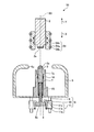
- FIG. 1 is a cross-sectional view showing a schematic configuration of a switch according to a first embodiment of the present invention.
- the switch 1 serving as a ground switch is used by being provided in a tank (not shown) filled with an insulating gas having an electrical insulating property and arc extinguishing property such as sulfur hexafluoride (SF 6 ) gas.
- the switch 1 includes a movable contact 2 that is a first contact, an arc contact 3 that is a second contact, a fixed contact 4 that is a third contact, a shield portion 5, An engagement portion 8 and an engagement mechanism portion 6 are provided.
- the movable contact 2 and the arc contact 3 are provided on the same operating shaft 50 and face each other.
- a direction parallel to the operation axis 50 and directed from the movable contact 2 to the arc contact 3 is indicated by an arrow X as a first direction.
- a direction parallel to the operation axis 50 and directed from the arc contact 3 to the movable contact 2 is indicated by an arrow Y as a second direction.
- the movable contact 2 is provided so as to be able to reciprocate along the operation axis 50.
- the movable contact 2 is a cylindrical conductor having an operation axis 50 as a central axis. As will be described in detail later, the movable contact 2 moves in the direction indicated by the arrow X, so that the tip 2a on the direction side indicated by the arrow X abuts on the arc contact 3, and the side 2b is fixed contact 4 Abut.
- the arc contact 3 is held by a guide portion 7 formed of a conductor, and can be reciprocated along the operation shaft 50.
- the arc contact 3 is secured to the guide portion 7 by a sliding contact 16 provided on the guide portion 7.
- the arc contact 3 is a cylindrical conductor centered on the operating axis 50.
- the tip portion 3 a on the direction side indicated by the arrow Y is formed of an arc-resistant material.
- the guide unit 7 surrounds the arc contact 3.
- the arc contact 3 is urged toward the direction indicated by the arrow Y by the urging portion 15.
- the urging unit 15 is a compression spring provided between the arc contact 3 and the guide unit 7, for example.
- FIG. 2 is a cross-sectional view showing a cut surface taken along the line II-II shown in FIG.
- the stationary contact 4 is provided around the arc contact 3 with the operation axis 50 as the center.
- the stationary contact 4 has a plurality of contact portions 4a, a biasing portion 4b, and a gap forming portion 4c.
- the plurality of contact portions 4 a are arranged in a ring around the arc contact 3 and the guide portion 7.
- the urging portion 4 b is an annular spring member that surrounds the plurality of contact portions 4 a from the outside, and urges the plurality of contact portions 4 a toward the operation shaft 50.
- the gap forming portion 4c is an annular member provided inside the plurality of contact portions 4a.
- the gap contact portion 4c contacts the plurality of contact portions 4a arranged in an annular shape from the inside to contact the arc contact 3 and the contact portions 4a. A gap is formed between the two.
- the movable contact 2 is inserted into the inside of the plurality of contact portions 4 a arranged in an annular shape, so that the contact 4 a contacts the side surface of the movable contact 2.
- the movable contact 2 is a movable-side main contact
- the contact portion 4a is a fixed-side main contact.
- the shield portion 5 is formed of a conductor and accommodates the arc contact 3, the fixed contact 4, and the guide portion 7 therein.
- the wall surface on the direction side indicated by the arrow Y in the shield portion 5 is formed with a first opening 5a in a region including a portion intersecting the operating axis 50, and the tip of the arc contact 3 in the state shown in FIG.
- the periphery of the part 3a is covered.
- the first opening 5a is formed in such a size that the movable contact 2 and the arc contact 3 can pass therethrough.
- a second opening 5b is formed on the wall surface of the shield portion 5 on the direction side indicated by the arrow X.
- the wall surface on the direction side indicated by the arrow X in the shield part 5 is in contact with the guide part 7.
- the engaged portion 8 is formed of an insulator and is integrally provided on the direction side indicated by the arrow X with respect to the arc contact 3.
- the engaged portion 8 passes through the second opening 5 b formed in the shield portion 5, and a part of the engaged portion 8 is exposed to the outside of the shield portion 5.
- FIG. 3 is a diagram of the engagement mechanism unit 6 according to the first embodiment viewed along a direction perpendicular to the operation axis 50.
- 4 is a cross-sectional view showing a cut surface taken along line IV-IV shown in FIG.
- the engaging mechanism section 6 includes a conductor section 9, an attracting section 10 that is a first magnetic body section, and an attracted section 11 that is a second magnetic body section.
- the conductor portion 9 is formed of a conductor and is provided away from the engaged portion 8 in a direction perpendicular to the operation shaft 50.
- the conductor portion 9 is in contact with the shield portion 5 and is electrically connected to the shield portion 5.
- the attracting part 10 is made of a magnetic material. Further, as shown in FIG. 4, the suction portion 10 has a shape in which the engaged portion 8 side is opened to surround the conductor portion 9.
- the suction part 10 is fixed to a tank (not shown) by a support part (not shown) formed of an insulator.
- suction part 10 may be fixed to the conductor part 9 with the screw
- the attracted part 11 is made of a magnetic material. Further, the attracted portion 11 is provided between the engaged portion 8 and the conductor portion 9. In the first embodiment, the attracted portion 11 is supported by the attracting portion 10 by the shaft portion 11a provided at the end portion on the direction side indicated by the arrow X, and can be rotated around the shaft portion 11a. ing. The attracted portion 11 is biased in the direction in which the end portion 11b on the arrow Y side moves toward the engaged portion 8 side. This biasing force is given by, for example, a torsion spring provided on the shaft portion 11a.
- the clearance gap is formed between the to-be-adsorbed part 11 and the adsorption
- An engaging portion 11 c that engages the engaged portion 8 and restricts the engaged portion 8 from moving in the direction indicated by the arrow Y is formed at the end portion 11 b of the attracted portion 11.
- the attracted portion 11 regulates that the arc contact 3 formed integrally with the engaged portion 8 moves in the direction indicated by the arrow Y by the biasing force of the biasing portion 15. can do.
- FIG. 5 is a side view showing a state of the engaging mechanism portion 6 when a current flows through the conductor portion 9 in the first embodiment.
- a current is passed through the conductor portion 9, an attracting force is generated between the attracting portion 10 and the attracted portion 11 due to a magnetic field generated around the conductor portion 9.
- the attracted portion 11 is attracted to the attracting portion 10 against the biasing force and moves to the attracting portion 10 side.
- the engagement of the engaging portion 11 c with the engaged portion 8 is released, and the arc contact 3 is moved to the arrow Y by the biasing force of the biasing portion 15. It can move in the direction shown.
- the movable contact 2 is moved from the state shown in FIG. 1 in the direction indicated by the arrow X, and the contact 4a of the movable contact 2 and the stationary contact 4 is obtained. The operation until the contact is made will be described.
- 6 to 8 are diagrams illustrating the operation of the switch 1 according to the first embodiment.
- the urging force of the urging unit 15 moves the arc contactor 2 in the direction indicated by the arrow Y, that is, moves toward the movable contactor 2 to move with the tip 2 a of the movable contactor 2.
- the tip 3a of the contact 3 comes into contact.
- the arc 12 disappears when the tip 2a of the movable contact 2 and the tip 3a of the movable contact 3 come into contact with each other.
- the movable contact 2 After the tip 2a of the movable contact 2 and the tip 3a of the movable contact 3 come into contact with each other, the movable contact 2 further moves in the direction indicated by the arrow X, as shown in FIG. 3 is pushed in the direction indicated by the arrow X against the urging force of the urging unit 15. And the side 2b of the movable contact 2 contacts the contact part 4a of the stationary contact 4 by the movable contact 2 being inserted inside the plurality of contact parts 4a arranged in an annular shape. If the switch 1 is a ground switch, the grounding is completed by the contact between the side surface 2b of the movable contact 2 and the contact portion 4a of the fixed contact 4.
- the attracted part 11 After completion of grounding, the attracted part 11 returns to the position away from the attracting part 10 when the current stops flowing to the conductor part 9. Therefore, if the movable contact 2 is moved in the direction shown by the arrow Y from the state shown in FIG. 8, the engaged portion 8 is engaged with the engaging portion 11c in the process, and the movable contact 2 and the arc contact are brought into contact with each other. 1 returns to the state shown in FIG.
- the arc contact 3 is directed toward the movable contact 2 when the arc 12 is generated between the arc contact 3 or the shield 5 and the movable contact 2. Therefore, after the arc 12 is generated, the movable contact 2 and the arc contact 3 approach each other at a relative speed obtained by adding the moving speed of the arc contact 3 to the moving speed of the movable contact 2.
- the arc contact 3 is moved to the movable contact 2 as compared with the configuration in which only the movable contact 2 is moved.
- the moving speed of the movable contact 2 can be reduced. That is, the moving speed of the movable contact 2 can be reduced while shortening the arc generation time.
- the operation device that is not shown for operating the movable contact can be downsized and reduced in size. Cost reduction can be achieved, and the switch 1 including the same can be reduced in size and cost.
- the urging force that separates the attracted part 11 from the attracting part 10 is not limited to that by the torsion spring as described above.
- the adsorbed part 11 is deformed when adsorbed by the adsorbing part 10 and the restoring force due to the elastic force of the adsorbed part 11 is increased.
- the biasing force is separated from the suction unit 10.
- the engaging mechanism unit 6 may be configured to be able to apply a force for separating the attracted portion 11 from the attracting portion 10.
- the switch 1 may be used for disconnectors other than a ground switch.
- FIG. FIG. 9 is sectional drawing which shows schematic structure of the switch concerning Embodiment 2 of this invention.
- symbol is attached
- the movable main contact 54 having the contact portion 54a, the urging portion 54b, and the gap forming portion 54c is the third contact like the fixed contact 4 in the first embodiment.
- the movable contact 2 is provided as a contact. More specifically, a plurality of contact portions 54 a are provided so as to surround the periphery of the movable contact 2.
- the movable main contact 54 moves together with the movable contact 2.
- the guide portion 7 is inserted inside the contact portion 54a, and the side surface 7a of the guide portion 7 contacts the contact portion 54a. That is, in the switch 51 according to the second embodiment, the contact portion 54a is a movable main contact, and the guide portion 7 is a fourth contact that is a fixed main contact.
- the opening 5a formed in the shield part 5 is formed with a size that allows the movable main contact 54 to pass therethrough.
- the movable contact 2 is moved from the state shown in FIG. 9 in the direction indicated by the arrow Y, and the contact 54a of the movable side main contact 54 and the guide portion 7 are moved. The operation until the side surface 7a is brought into contact will be described.
- 10 to 12 are diagrams for explaining the operation of the switch 51 according to the second embodiment.
- the arc contact 2 moves in the direction indicated by the arrow Y by the urging force of the urging portion 15, that is, moves toward the movable contact 2, and the distal end portion 2 a of the movable contact 2.
- the tip 3a of the arc contact 3 come into contact with each other.
- the arc 12 disappears when the tip 2a of the movable contact 2 and the tip 3a of the arc contact 3 come into contact with each other.
- the movable contact 2 After the contact between the tip 2a of the movable contact 2 and the tip 3a of the arc contact 3, the movable contact 2 further moves in the direction indicated by the arrow X, so that the arc contact as shown in FIG. 3 is pushed in the direction indicated by the arrow X against the urging force of the urging unit 15. Then, the guide portion 7 is inserted inside the plurality of contact portions 54 a arranged in a ring shape, so that the side surface 7 a of the guide portion 7 comes into contact with the contact portion 54 a of the movable side main contact 54. If the switch 51 is a ground switch, the grounding is completed by the contact between the side surface 7a of the guide portion 7 and the contact portion 54a of the movable main contact 54.
- the attracted part 11 After completion of grounding, the attracted part 11 returns to the position away from the attracting part 10 when the current stops flowing to the conductor part 9. Therefore, if the movable contact 2 is moved in the direction shown by the arrow Y from the state shown in FIG. 12, the engaged portion 8 is engaged with the engaging portion 11c in the process, and the movable contact 2 and the arc contact The state returns to the state shown in FIG. 9 where the child 3 is separated.
- the switch 51 described above since the arc contact 3 moves toward the movable contact 2 when the arc 12 is generated, the moving speed of the movable contact 2 is increased after the arc 12 is generated.
- the movable contact 2 and the arc contact 3 come close to each other at a relative speed obtained by adding the moving speed of the arc contact 3. Therefore, similarly to the first embodiment, it is possible to reduce the moving speed of the movable contact 2 while shortening the arc generation time.
- the configuration described in the above embodiment shows an example of the contents of the present invention, and can be combined with another known technique, and can be combined with other configurations without departing from the gist of the present invention. It is also possible to omit or change the part.
Landscapes
- Arc-Extinguishing Devices That Are Switches (AREA)
- Gas-Insulated Switchgears (AREA)
Abstract
Priority Applications (4)
| Application Number | Priority Date | Filing Date | Title |
|---|---|---|---|
| EP16897894.8A EP3441998B1 (fr) | 2016-04-06 | 2016-04-06 | Interrupteur |
| PCT/JP2016/061270 WO2017175336A1 (fr) | 2016-04-06 | 2016-04-06 | Interrupteur |
| US16/089,165 US10566155B2 (en) | 2016-04-06 | 2016-04-06 | Switch |
| JP2016547195A JP6058230B1 (ja) | 2016-04-06 | 2016-04-06 | 開閉器 |
Applications Claiming Priority (1)
| Application Number | Priority Date | Filing Date | Title |
|---|---|---|---|
| PCT/JP2016/061270 WO2017175336A1 (fr) | 2016-04-06 | 2016-04-06 | Interrupteur |
Publications (1)
| Publication Number | Publication Date |
|---|---|
| WO2017175336A1 true WO2017175336A1 (fr) | 2017-10-12 |
Family
ID=57756213
Family Applications (1)
| Application Number | Title | Priority Date | Filing Date |
|---|---|---|---|
| PCT/JP2016/061270 Ceased WO2017175336A1 (fr) | 2016-04-06 | 2016-04-06 | Interrupteur |
Country Status (4)
| Country | Link |
|---|---|
| US (1) | US10566155B2 (fr) |
| EP (1) | EP3441998B1 (fr) |
| JP (1) | JP6058230B1 (fr) |
| WO (1) | WO2017175336A1 (fr) |
Cited By (2)
| Publication number | Priority date | Publication date | Assignee | Title |
|---|---|---|---|---|
| CN109616373A (zh) * | 2018-12-12 | 2019-04-12 | 西安交通大学 | 一种真空灭弧室复合触头、真空灭弧室及真空断路器 |
| KR20220136608A (ko) * | 2021-04-01 | 2022-10-11 | 엘에스일렉트릭(주) | 가스절연개폐장치 |
Families Citing this family (1)
| Publication number | Priority date | Publication date | Assignee | Title |
|---|---|---|---|---|
| WO2019097681A1 (fr) * | 2017-11-17 | 2019-05-23 | 三菱電機株式会社 | Dispositif d'ouverture/fermeture |
Citations (3)
| Publication number | Priority date | Publication date | Assignee | Title |
|---|---|---|---|---|
| JPH07211199A (ja) * | 1994-01-20 | 1995-08-11 | Toshiba Corp | 遮断装置 |
| JP2007027023A (ja) * | 2005-07-21 | 2007-02-01 | Hitachi Ltd | ガス絶縁開閉器 |
| JP2009163946A (ja) | 2007-12-28 | 2009-07-23 | Mitsubishi Electric Corp | 接地開閉器 |
Family Cites Families (10)
| Publication number | Priority date | Publication date | Assignee | Title |
|---|---|---|---|---|
| CA1005499A (en) * | 1972-12-11 | 1977-02-15 | Frank S. Nichols | Load break device and arc-extinguishing material therefor |
| CH651961A5 (de) * | 1978-09-04 | 1985-10-15 | Mitsubishi Electric Corp | Schalter mit automatischer lichtbogenloeschung. |
| JPS5755024A (en) | 1980-09-19 | 1982-04-01 | Mitsubishi Electric Corp | Power switching device |
| JPS58165221A (ja) * | 1982-03-25 | 1983-09-30 | 三菱電機株式会社 | 断路器 |
| JPH0719504B2 (ja) * | 1988-11-08 | 1995-03-06 | 三菱電機株式会社 | 断路器 |
| JP2743740B2 (ja) * | 1992-11-05 | 1998-04-22 | 三菱電機株式会社 | ガス絶縁開閉器 |
| JPH07249356A (ja) | 1994-03-10 | 1995-09-26 | Meidensha Corp | ガス断路器 |
| DE102010062343A1 (de) * | 2010-12-02 | 2012-06-06 | Siemens Aktiengesellschaft | Elektrokontaktanordnung |
| JP5389279B2 (ja) * | 2011-01-07 | 2014-01-15 | 三菱電機株式会社 | 開閉装置 |
| JP5629589B2 (ja) | 2011-01-19 | 2014-11-19 | 株式会社東芝 | 開閉器 |
-
2016
- 2016-04-06 EP EP16897894.8A patent/EP3441998B1/fr active Active
- 2016-04-06 WO PCT/JP2016/061270 patent/WO2017175336A1/fr not_active Ceased
- 2016-04-06 US US16/089,165 patent/US10566155B2/en active Active
- 2016-04-06 JP JP2016547195A patent/JP6058230B1/ja active Active
Patent Citations (3)
| Publication number | Priority date | Publication date | Assignee | Title |
|---|---|---|---|---|
| JPH07211199A (ja) * | 1994-01-20 | 1995-08-11 | Toshiba Corp | 遮断装置 |
| JP2007027023A (ja) * | 2005-07-21 | 2007-02-01 | Hitachi Ltd | ガス絶縁開閉器 |
| JP2009163946A (ja) | 2007-12-28 | 2009-07-23 | Mitsubishi Electric Corp | 接地開閉器 |
Non-Patent Citations (1)
| Title |
|---|
| See also references of EP3441998A4 |
Cited By (3)
| Publication number | Priority date | Publication date | Assignee | Title |
|---|---|---|---|---|
| CN109616373A (zh) * | 2018-12-12 | 2019-04-12 | 西安交通大学 | 一种真空灭弧室复合触头、真空灭弧室及真空断路器 |
| KR20220136608A (ko) * | 2021-04-01 | 2022-10-11 | 엘에스일렉트릭(주) | 가스절연개폐장치 |
| KR102833102B1 (ko) | 2021-04-01 | 2025-07-14 | 엘에스일렉트릭(주) | 가스절연개폐장치 |
Also Published As
| Publication number | Publication date |
|---|---|
| JP6058230B1 (ja) | 2017-01-11 |
| US20190371546A1 (en) | 2019-12-05 |
| US10566155B2 (en) | 2020-02-18 |
| EP3441998A1 (fr) | 2019-02-13 |
| EP3441998A4 (fr) | 2019-02-27 |
| JPWO2017175336A1 (ja) | 2018-04-12 |
| EP3441998B1 (fr) | 2019-10-09 |
Similar Documents
| Publication | Publication Date | Title |
|---|---|---|
| CN103238196B (zh) | 电接触装置 | |
| KR101704807B1 (ko) | 차단기용 전자반발 조작기 | |
| CN104465201A (zh) | 开关 | |
| KR101919125B1 (ko) | 고압 배전기의 가스절연 개폐장치 | |
| JP6058230B1 (ja) | 開閉器 | |
| CN105474343A (zh) | 开关器 | |
| JP6067182B1 (ja) | 開閉器 | |
| CN102610426B (zh) | 开关 | |
| CN102034640B (zh) | 具有并联额定电流路径的功率开关 | |
| JP6370518B1 (ja) | 開閉装置 | |
| JP6136598B2 (ja) | 封止形リレー | |
| WO2017187635A1 (fr) | Commutateur | |
| KR101771637B1 (ko) | 밀봉형 릴레이 | |
| KR101696955B1 (ko) | 전자 개폐기 | |
| KR101704989B1 (ko) | 회로차단기의 가동접촉자 | |
| CN109416993A (zh) | 具有灭弧装置的开关 | |
| CN111758142B (zh) | 开关 | |
| KR20230099166A (ko) | 가스절연 전력개폐장치 | |
| JP6989373B2 (ja) | 開閉器 | |
| WO2019097681A1 (fr) | Dispositif d'ouverture/fermeture | |
| WO2019064447A1 (fr) | Dispositif de commutation | |
| CN109643619A (zh) | 开关和用于断路开关的方法 | |
| JP5798019B2 (ja) | ガス絶縁開閉機器 | |
| KR101605138B1 (ko) | 단로기 | |
| WO2016027499A1 (fr) | Dispositif de commutation |
Legal Events
| Date | Code | Title | Description |
|---|---|---|---|
| ENP | Entry into the national phase |
Ref document number: 2016547195 Country of ref document: JP Kind code of ref document: A |
|
| NENP | Non-entry into the national phase |
Ref country code: DE |
|
| 121 | Ep: the epo has been informed by wipo that ep was designated in this application |
Ref document number: 16897894 Country of ref document: EP Kind code of ref document: A1 |
|
| WWE | Wipo information: entry into national phase |
Ref document number: 2016897894 Country of ref document: EP |
|
| ENP | Entry into the national phase |
Ref document number: 2016897894 Country of ref document: EP Effective date: 20181106 |