WO2017175659A1 - Support de boulon de suspension - Google Patents
Support de boulon de suspension Download PDFInfo
- Publication number
- WO2017175659A1 WO2017175659A1 PCT/JP2017/013296 JP2017013296W WO2017175659A1 WO 2017175659 A1 WO2017175659 A1 WO 2017175659A1 JP 2017013296 W JP2017013296 W JP 2017013296W WO 2017175659 A1 WO2017175659 A1 WO 2017175659A1
- Authority
- WO
- WIPO (PCT)
- Prior art keywords
- suspension bolt
- pair
- bolt support
- male screw
- wall portions
- Prior art date
- Legal status (The legal status is an assumption and is not a legal conclusion. Google has not performed a legal analysis and makes no representation as to the accuracy of the status listed.)
- Ceased
Links
Images


Classifications
-
- E—FIXED CONSTRUCTIONS
- E04—BUILDING
- E04B—GENERAL BUILDING CONSTRUCTIONS; WALLS, e.g. PARTITIONS; ROOFS; FLOORS; CEILINGS; INSULATION OR OTHER PROTECTION OF BUILDINGS
- E04B9/00—Ceilings; Construction of ceilings, e.g. false ceilings; Ceiling construction with regard to insulation
- E04B9/18—Means for suspending the supporting construction
-
- F—MECHANICAL ENGINEERING; LIGHTING; HEATING; WEAPONS; BLASTING
- F16—ENGINEERING ELEMENTS AND UNITS; GENERAL MEASURES FOR PRODUCING AND MAINTAINING EFFECTIVE FUNCTIONING OF MACHINES OR INSTALLATIONS; THERMAL INSULATION IN GENERAL
- F16B—DEVICES FOR FASTENING OR SECURING CONSTRUCTIONAL ELEMENTS OR MACHINE PARTS TOGETHER, e.g. NAILS, BOLTS, CIRCLIPS, CLAMPS, CLIPS OR WEDGES; JOINTS OR JOINTING
- F16B1/00—Devices for securing together, or preventing relative movement between, constructional elements or machine parts
-
- F—MECHANICAL ENGINEERING; LIGHTING; HEATING; WEAPONS; BLASTING
- F16—ENGINEERING ELEMENTS AND UNITS; GENERAL MEASURES FOR PRODUCING AND MAINTAINING EFFECTIVE FUNCTIONING OF MACHINES OR INSTALLATIONS; THERMAL INSULATION IN GENERAL
- F16B—DEVICES FOR FASTENING OR SECURING CONSTRUCTIONAL ELEMENTS OR MACHINE PARTS TOGETHER, e.g. NAILS, BOLTS, CIRCLIPS, CLAMPS, CLIPS OR WEDGES; JOINTS OR JOINTING
- F16B13/00—Dowels or other devices fastened in walls or the like by inserting them in holes made therein for that purpose
- F16B13/04—Dowels or other devices fastened in walls or the like by inserting them in holes made therein for that purpose with parts gripping in the hole or behind the reverse side of the wall after inserting from the front
Definitions
- the present invention relates to a suspension bolt support bracket that supports a suspension bolt suspended from a deck plate.
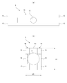
- FIG. 17 is a view showing one type of the deck plate 9.
- a deck plate 9 shown in FIG. 17 has a plurality of slits 9a each having a width of about 12 to 14 mm arranged in parallel at a predetermined interval, and has a substantially trapezoidal upper space 8 above each slit 9a.
- the upper space 8 is formed such that the width of the lower slit 9a is the narrowest and the width becomes wider from the slit 9a toward the upper portion.
- the upper space 8 of each slit 9a is used as a structure for supporting the suspension bolt.
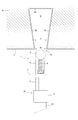
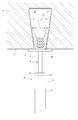
- FIG. 18 is a diagram illustrating a conventional construction method for attaching the suspension bolt 7 to the upper space 8 of each slit 9 a of the deck plate 9.
- a fixture 100 in which a pair of paper pieces 102 and 103 are bonded to both ends of a nut 101 is used. That is, in the conventional construction method, as shown in FIG. 18A, the operator inserts the nut 101 into the upper space 8 from the slit 9 a and pulls the paper pieces 102 and 103 at both ends of the nut 101 to thereby remove the nut 101. Both ends are arranged to engage with the inner wall of the upper space 8.
- the operator holds the tip of the suspension bolt 7 with the nut 101 in a state where the posture of the nut 101 is stabilized by pressing the paper pieces 102 and 103 extending from both ends of the nut 101 with a fingertip or the like. Insert it into the screw hole.
- the construction method shown in FIG. 18 has a problem that it takes time to stabilize the posture of the nut 101 in the upper space 8 after the nut 101 is inserted into the slit 9a.
- the above-mentioned work is a high place work for the worker. Therefore, every time the installation work of one suspension bolt 7 is completed, the worker once gets down to the floor and puts a stepladder or a step on the next attachment position. Therefore, when attaching a plurality of suspension bolts 7, there is a problem that it takes a lot of time and labor.
- the present invention has been made to solve the above-described conventional problems, and a suspension bolt support bracket that has improved work efficiency when attaching a suspension bolt to a deck plate provided with slits.
- the purpose is to provide.
- a slit (9a) having a predetermined width (D) is formed on the lower surface, and the distance between the slits (9a) is gradually enlarged from both ends toward the upper part.
- a suspension bolt support bracket (1, 1a, 60) that is attached to the plate (9) and supports the suspension bolt (7) in a state of being attached to the deck plate (9), the deck plate (9)
- the male screw member (4, 61a) inserted into the space between the pair of wall portions (9b, 9c) from the slit (9a) and the male screw member (4, 61a) are attached to the male screw member.
- the width is smaller than the width of the slit (9a) and gradually decreases from the maximum width portion toward the lower portion, and the lower portion of the maximum width portion is the pair of extended wall portions (5b, 5c).
- a widening member (6) attached in a state of being inserted into the male screw member (4, 61a), and joined to the lower surface of the deck plate (9), and the suspension bolt (7) is attached.
- the suspension bolt support bracket can be firmly fixed to the slit of the deck plate with a simple operation, and the working efficiency is improved as compared with the conventional one.
- the suspension bolt support member (70) is constituted by a long nut (2), and the long nut (2 ),
- the suspension bolt (7) can be attached to the screw hole (2b) formed in the lower surface.
- the suspension bolt support member (70) is a washer (3) attached to the male screw member (4).
- the widening member (6) and the expansion member (5) are inserted between the pair of wall portions (9b, 9c) from the slit (9a) in the deck plate (9), and As the long nut (2) rotates with the washer (3) in contact with the edge of the slit (9a) in the deck plate (9), the widening member (6) is lowered.
- the pair of expansion wall portions (5b, 5c) is expanded by entering the inside of the pair of expansion wall portions (5b, 5c), and the pair of expansion wall portions (5b, 5c) is expanded to the deck plate (
- the structure is characterized in that it is closely fixed to the pair of wall portions (9b, 9c) in 9).
- the male screw member (4) has a smaller diameter than the suspension bolt (7). It is the structure characterized by these.
- the suspension bolt support bracket can be fixed to the slit even when the gap between the slits in the deck plate is narrow.
- the long nut (2) has a predetermined inner diameter from the lower surface to a position at the first depth.
- a screw hole (30a) having a diameter smaller than the predetermined inner diameter from the position of the first depth to the position of the second depth and capable of mounting the suspension bolt (7). 2b), and an annular fracture groove (31) is provided at a predetermined position outside the portion where the hole (30a) having the predetermined inner diameter is formed.
- the torque at the time of attaching the suspension bolt support bracket to the slit of the deck plate can be managed, it is possible to attach the suspension bolt support bracket with stable strength.
- the present invention further includes a cap member (30b) for closing the hole (30a) having the predetermined inner diameter in the suspension bolt support fitting (1a) having the fifth configuration, and the breaking groove (31) When ruptures, the cap member (30b) is removed from the long nut (2) together with the lower end side of the rupture groove (31) of the long nut (2).
- the mounting of the suspension bolt can be prevented by the cap member.
- the long nut (2) can be mounted with the suspension bolt (7).
- a deformable material (40) is provided, and the deformable material (40) is deformed along with the attachment of the suspension bolt (7) to the screw hole (2b), and a part of the deformable material (40) is formed in the communication hole (2c). ) To the outside.
- the sixth configuration it is possible to easily check the mounting state of the suspension bolt on the lower surface of the long nut, so that the work efficiency is improved.
- the deck plate (9) includes a plurality of slits (9a) arranged at predetermined intervals,
- the suspension bolt support member (70) is supported by the rail member (65) longer than the interval provided with the plurality of slits (9a) in the deck plate (9), and the rail member (65),
- a suspension bolt connecting member (67) capable of adjusting the position along the longitudinal direction of the rail member (65) and capable of attaching the suspension bolt (7) is provided.
- the ninth configuration it is possible to attach the suspension bolt in a suspended state even at a position where the slit of the deck plate is not provided.
- the suspension bolt connecting member (67) has a through screw hole into which the suspension bolt (7) can be attached.
- the tip of the suspension bolt (7) attached to the through screw hole is fixed in the longitudinal direction of the rail member (65) by pressing the rail member (65). is there.
- the suspension bolt can be fixed at an arbitrary position of the rail member.
- the present invention provides the suspension bolt support bracket (1, 1a, 60) having any one of the first to sixth configurations, wherein the expansion member (5) is formed on the base end (5a). It has an insertion hole (11) through which the male screw member (4) can be inserted in the center, and both ends of the pair of expansion wall portions (5b, 5c) are thicker toward the inside than the center portion. It is a structure characterized by having a thick part (15).
- the thick portion (15) constitutes the pair of extension wall portions (5b, 5c). It is characterized in that the plate member to be stacked is superimposed on the inside of the pair of extension wall portions (5b, 5c).
- this invention is provided in the both ends of a pair of said extended wall part (5b, 5c) in the suspension bolt support metal fitting (1, 1a, 60) which has the said 10th or 11th structure.
- An interval between the thick portions (15) facing each other is smaller than a diameter of the male screw member (4).
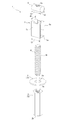
- FIG. 1 is a perspective view showing separately the constituent members of the suspension bolt support fitting 1 according to the first embodiment of the present invention, and FIG. 2 shows the assembled state of the constituent members of the suspension bolt support fitting 1.
- FIG. 3A is a side view of the suspension bolt support fitting 1
- FIG. 3B is a cross-sectional view of the suspension bolt support fitting 1.
- the suspension bolt support fitting 1 includes a long nut 2, a washer 3, a male screw member 4, an expansion member 5, and a widening member 6.
- the suspension bolt support fitting 1 is used in a state where the plurality of constituent members are assembled. For example, as shown in FIG.
- the suspension bolt support fitting 1 has a slit 9a having a predetermined width D formed on the lower surface, and a pair of wall portions 9b that gradually increase the distance from both ends of the slit 9a upward. 9c and a steel deck plate 9 having a top plate portion 9d for connecting the upper ends of the pair of wall portions 9b, 9c to each other at a predetermined height from the slit 9a. It is the metal fitting which supports 7 in the suspended state. That is, the suspension bolt support fitting 1 is attached to engage with the pair of wall portions 9b and 9c in the upper space 8 of the slit 9a of the deck plate 9, and is formed on the lower surface of the long nut 2 as shown in FIG. This is a bracket that supports the suspension bolt 7 in a state where the suspension bolt 7 is attached to the screw hole 2b.
- the suspension bolt support fitting 1 is fixed to the upper space 8 of the slit 9 a after a ceiling slab S such as concrete is placed on the upper surface of the deck plate 9.
- the width D of the slit 9a is, for example, about 12 to 14 mm.
- the suspension bolt support fitting 1 of the present embodiment is attached to the upper space 8 via the slit 9a having a width D that is approximately 20 to 40% larger than the diameter of the suspension bolt 7.
- a suspension bolt support fitting 1 will be described in detail.
- the long nut 2 and the washer 3 of the suspension bolt support fitting 1 are attached to the lower portion of the male screw member 4 and constitute a suspension bolt support member 70 to which the suspension bolt 7 can be attached in a state of being joined to the lower surface of the deck plate 9. It is. That is, the suspension bolt support member 70 is a member that supports the suspension bolt 7 in a suspended state from the lower surface of the deck plate 9.
- the long nut 2 of the suspension bolt support fitting 1 has a predetermined length along the axial direction (vertical direction) of the male screw member 4, and is a hexagon nut having screw holes 2a and 2b formed on both the upper surface and the lower surface thereof. It is. As shown in FIG. 3B, for example, the two screw holes 2a and 2b are formed as screw holes of different diameters so as to be screwed with male screws of different sizes.
- the screw hole 2a formed on the upper surface of the long nut 2 is formed with an M8 size screw hole so as to be screwed with an M8 bolt.
- the screw hole 2b formed on the lower surface is formed with a screw hole having a size of M10 so as to be engaged with the suspension bolt 7 of M10, for example.
- the long nut 2 is configured such that the first screw hole 2a and the second screw hole 2b communicate with each other at a substantially central position.
- the bottoms of the first screw hole 2a and the second screw hole 2b refer to a portion where the first screw hole 2a and the second screw hole 2b communicate with each other.
- the first screw hole 2a and the second screw hole 2b may be configured as screw holes of the same size. Further, the first screw hole 2 a and the second screw hole 2 b do not necessarily have to communicate with each other inside the long nut 2.
- the male screw member 4 has a predetermined length along the axial direction, and the male screw 4a is formed on the outer peripheral surface over the entire axial direction.
- the male screw member 4 is configured by an M8 bolt having a smaller diameter than the suspension bolt 7.
- the male screw member 4 is mounted in a screw hole 2 a having a lower portion formed in the surface of the long nut 2.
- the male screw member 4 is attached to the screw hole 2a so that the lower end of the male screw member 4 is slightly lifted from the bottom of the screw hole 2a.
- the washer 3 is a disk-shaped member in which a hole 3a through which the male screw member 4 can be inserted is formed at the center thereof.
- the outer diameter of the washer 3 is formed larger than the width D of the slit 9 a in the deck plate 9.
- the inner diameter of the hole 3a is larger than the outer diameter of the male screw member 4 and smaller than the outer diameter of the long nut 2.
- the washer 3 is attached to the suspension bolt support fitting 1 by inserting a male screw member 4 mounted on the upper surface of the long nut 2 into the central hole 3a. That is, the washer 3 is attached with its lower surface joined to the upper surface of the long nut 2.
- the expansion member 5 is erected so as to face the base end portion 5a in which the hole 11 through which the male screw member 4 is inserted and the both ends of the base end portion 5a in a substantially parallel state with a predetermined distance from each other. It has a pair of expansion wall parts 5b and 5c.
- Such an expansion member 5 is a member formed by bending a metal plate that has been processed into a predetermined shape in advance.
- FIG. 4 is a diagram showing a plan view of the metal plate 10 and the expansion member 5 as the base material of the expansion member 5 as viewed from above.
- the metal plate 10 that is a base material of the expansion member 5 has a substantially H-shaped shape, and is provided at two locations at both ends in the longitudinal direction (both ends 2 in the short direction). A total of four extending portions 12 extending outward) are provided.
- the metal plate 10 has a hole 11 slightly larger than the outer diameter of the male screw member 4 at the center thereof.
- the expansion member 5 has a thick portion 15 formed by bending the extending portion 12 inward at both ends of the pair of expansion wall portions 5b and 5c.
- the thick portion 15 has a thickness in which two metal plates 10 are overlapped.
- the central portion 16 of the pair of extension wall portions 5b and 5c is thinner than the thick portion 15 because the metal plate 10 is not overlapped.
- interval of the center part 16 of a pair of extended wall part 5b, 5c is substantially the same as the diameter of the hole 11 formed in the base end part 5a, and is penetrated by the hole 11. The spacing is slightly larger than the outer diameter of the male screw member 4.
- the thick portions 15 at both ends of the pair of extension wall portions 5b and 5c are twice as thick as the central portion 16, the interval between the thick portions 15 facing each other is larger than the diameter of the male screw member 4. Get smaller.
- the thick portions 15 provided at both ends of the pair of extension wall portions 5b and 5c are positioned on the outer periphery of the male screw member 4. Therefore, it does not interfere with the male screw member 4.
- the extension member 5 is formed such that the lateral length L1 of the pair of extension wall portions 5b and 5c is slightly larger than the interval D of the slits 9a in the deck plate 9, and has a predetermined length of about 15 mm, for example. Formed. That is, the relationship between the lateral length L1 of the pair of extension wall portions 5b and 5c and the distance D between the slits 9a in the deck plate 9 is L1> D. Further, the pair of extension wall portions 5b and 5c are disposed so as to stand up at an interval W1 that is equal to or smaller than the width D of the slit 9a in the deck plate 9.
- the relationship between the interval W1 between the outer side surfaces of the pair of extension wall portions 5b and 5c erected in a substantially parallel state and the interval D of the slit 9a in the deck plate 9 is W1 ⁇ D.
- the expansion member 5 can be inserted into the upper space 8 of the slit 9a via the slit 9a when the pair of expansion wall portions 5b and 5c are in a state parallel to the slit 9a, and the upper space of the slit 9a. After being inserted into 8, it does not rotate around the axis of the male screw member 4.
- the expansion member 5 configured as described above has a male screw member in the hole 11 formed in the base end portion 5a with the distal ends of the pair of expansion wall portions 5b and 5c facing upward. 4 is inserted. Therefore, when the expansion member 5 is attached to the male screw member 4, the base end portion 5 a is joined to the upper surface of the washer 3.
- the widening member 6 is, for example, a nut member attached to the tip (upper end) of the male screw member 4.
- the widening member 6 in the present embodiment is a member in which, for example, a cylindrical metal fitting having a predetermined length is arranged in the horizontal direction, and a through screw hole 6a penetrating in the vertical direction through the center of the metal fitting is formed on the outer peripheral surface thereof.
- the through screw hole 6a is a screw hole that is screwed with the tip of the male screw member 4, and is formed as a screw hole of M8 size so as to be screwed with the male screw member 4 of M8 size, for example.
- the widening member 6 has substantially the same length L2 as the pair of expansion wall portions 5b and 5c in the longitudinal direction perpendicular to the axial direction of the male screw member 4. That is, the length L2 in the longitudinal direction of the widening member 6 is substantially the same as the length L1 in the lateral direction of the pair of expansion wall portions 5b and 5c. Further, the maximum width W2 of the widening member 6 in the short direction perpendicular to the axial direction of the male screw member 4 is equal to or smaller than the width D of the slit 9a in the deck plate 9. That is, the relationship between the maximum width W2 of the widening member 6 and the interval D of the slits 9a in the deck plate 9 is W2 ⁇ D.
- the maximum width W2 of the widening member 6 corresponds to the diameter of the cylindrical metal fitting.
- the widening member 6 since the widening member 6 is used with a cylindrical metal member arranged in the horizontal direction, the width gradually decreases from the portion of the maximum width W2 in the short direction perpendicular to the axial direction of the male screw member 4 toward the lower part. It has a shape to
- the widening member 6 as described above has the tip 4b of the male screw member 4 screwed into the through screw hole 6a.
- the widening member 6 is attached to the tip of the male screw member 4 so as to be parallel to the pair of expansion wall portions 5b, 5c, and the lower portion of the widening member 6 is a pair of expansion wall portions 5b, 5c. Is attached to the tip 4b of the male screw member 4 so as to be fitted into the tip of the screw.
- the arcuate lower portion of the widening member 6 bends the inside of the distal end portion of the thick portion 15 in the pair of expansion wall portions 5b and 5c, that is, the extension portion 12.
- the widening member 6 is attached to the male screw member 4 so as to engage with the inside of the curved portion generated by the operation.
- the suspension bolt support fitting 1 When the constituent members are assembled as described above, the suspension bolt support fitting 1 has a width W smaller than the width D of the slit 9a at the upper part above the washer 3, as shown in FIG. . Therefore, the suspension bolt support metal fitting 1 is configured as a metal fitting capable of inserting the upper part composed of the expansion member 5 and the widening member 6 into the upper space 8 through the gap of the slit 9a in the deck plate 9.
- the male screw member 4 is attached to the screw hole 2a formed on the upper surface of the long nut 2, and then the washer 3, the expansion member 5 and the widening member 6 are sequentially attached to the male screw member 4.
- the assembling order of the suspension bolt support fitting 1 is not limited to this.
- the suspension bolt support metal fitting 1 has the widening member 6 attached to the front end 4b of the male screw member 4 contrary to the above, and then the expansion member 5, the washer 3 and the long nut 2 are sequentially attached to the male screw member. You may make it mount to the lower part of 4.
- FIG. 1
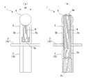
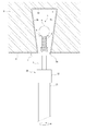
- 5 to 8 are diagrams showing each step in the construction method using the suspension bolt support fitting 1.
- the worker attaches the work tool 20 to the lower part of the long nut 2 of the suspension bolt support fitting 1.
- the work tool 20 includes, for example, a long shaft portion 21 and an engagement portion 22 provided at the tip of the shaft portion 21 so that an operator can work from the floor surface.
- the engaging portion 22 is a cylindrical portion that can be held by inserting the lower portion of the long nut 2.
- the inner wall of the engaging portion 22 is formed in a hexagonal shape, and is configured to engage with the outer peripheral surface of the long nut 2.
- the operator attaches the work tool 20 to the lower portion of the long nut 2 of the suspension bolt support bracket 1 and then lifts the tip of the shaft portion 21 while holding the lower end of the shaft portion 21 so that the suspension bolt support bracket 1 is mounted on the deck.
- the plate 9 is disposed in the vicinity of the slit 9a. Then, the worker places the widening member 6 of the suspension bolt support fitting 1 in a state substantially parallel to the slit 9 a of the deck plate 9. Thereby, it becomes possible to insert the upper part of the suspension bolt support metal fitting 1 into the upper space 8 of the slit 9a through the gap of the slit 9a.
- the operator lifts the shaft portion 21 of the work tool 20 to insert the upper portion of the suspension bolt support fitting 1 from the lower side to the upper side of the slit 9a.
- the operator inserts the upper portion of the suspension bolt support fitting 1 until the washer 3 comes into contact with the edge of the slit 9a. That is, the washer 3 functions as a stopper that prevents excessive insertion of the suspension bolt support fitting 1 into the upper space 8 of the slit 9a, and also has a function of positioning the position of the expansion member 5 in the vicinity of the slit 9a. is doing.
- the state shown in FIG. 6 is obtained. That is, the expansion member 5 and the widening member 6 of the suspension bolt support fitting 1 are inserted into the upper space 8 of the slit 9 a in the deck plate 9.
- the worker attaches an electric tool or the like to the lower end of the shaft portion 21 of the work tool 20 and rotates the shaft portion 21 in a predetermined rotation direction (clockwise direction) R.
- a predetermined rotation direction clockwise direction
- the work tool 20 is rotated, the long nut 2 of the suspension bolt support 1 is rotated together with the work tool 20.
- the male screw member 4 also tries to rotate together with the work tool 20, and the expansion member 5 and the widening member 6 inserted in the upper space 8 of the slit 9a also rotate in the rotation direction R.
- the pair of extension wall portions 5b. , 5 c interfere with the pair of wall portions 9 b, 9 c in the upper space 8. Therefore, even if the long nut 2 rotates, the expansion member 5 and the widening member 6 are not rotated together with the long nut 2 because the rotation is restricted by the pair of wall portions 9b and 9c.
- the male screw member 4 also does not rotate with the long nut 2 because the widening member 6 does not rotate. As a result, the male screw member 4 moves downward as the long nut 2 rotates.
- the male screw member 4 moves toward the bottom of the screw hole 2 a formed in the long nut 2.
- the widening member 6 also moves downward together with the male screw member 4.
- the widening member 6 presses the pair of expansion wall portions 5b and 5c of the expansion member 5 outward.
- the pair of expansion wall portions 5b and 5c are subjected to a pressing force from the widening member 6 and are deformed in a direction in which their tips are expanded.
- the pair of extension wall portions 5b and 5c press the pair of wall portions 9b and 9c in the upper space 8 of the slit 9a, and the suspension bolt support fitting 1 is placed in the upper space 8 of the slit 9a. Fixed.
- the suspension bolt support fitting 1 can be fixed in the upper space 8 of the slit 9a.
- the suspension bolt support fitting 1 When the suspension bolt support fitting 1 is attached to the upper space 8 of the slit 9a as described above, the thick portion 15 of the pair of expansion wall portions 5b, 5c is interposed between the widening member 6 and the pair of wall portions 9b, 9c. It will be in the state where it was inserted. That is, the suspension bolt support fitting 1 presses the pair of wall portions 9b, 9c in the upper space 8 of the slit 9a through the thick portions 15 of the pair of extension wall portions 5b, 5c, thereby lowering the widening member 6 below. Since the amount of movement to can be reduced, there is an advantage that the entire fitting can be reduced in size.
- the construction for fixing the suspension bolt 7 to the deck plate 9 using the suspension bolt support bracket 1 is completed.
- work of each process mentioned above is an operation
- the suspension bolt support fitting 1 that supports the suspension bolt 7 is firmly fixed to the upper space 8 of the slit 9a, the suspension bolt 7 can be held in a stable posture. There is an advantage that vibration of the suspension bolt 7 can also be suppressed.
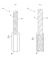
- FIGS. 9A and 9B are views showing an example of a member 51 in which the long nut 2 and the male screw member 4 are integrally formed.
- FIG. 9A is a perspective view of the member 51, and FIG. A cross-sectional view is shown.
- the member 51 is configured as one part in which the male screw member 4 is joined in advance to one end of the long nut 2, and the suspension bolt 7 is attached to the other end (lower surface) of the long nut 2. Screw hole 2b is formed.
- the member 51 in which the long nut 2 and the male screw member 4 are integrated can form a deeper screw hole 2b for mounting the suspension bolt 7, so that when the suspension bolt 7 is mounted, Stability is improved. Further, when the member 51 is used, it is not necessary to assemble the long nut 2 and the male screw member 4, so that the working efficiency is further improved.
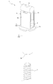
- FIG. 10 is a perspective view showing a state in which the constituent members of the suspension bolt support fitting 1a according to the second embodiment of the present invention are assembled.
- 11A is a cross-sectional view of the suspension bolt support fitting 1a
- FIG. 11B is a view showing the deformable member 40 that is mounted in advance on the bottom of the screw hole 2b of the long nut 2.
- the suspension bolt support fitting 1a Similar to the suspension bolt support fitting 1 of the first embodiment, the suspension bolt support fitting 1a includes a long nut 2, a washer 3, a male screw member 4, an expansion member 5, and a widening member 6. .
- This suspension bolt support fitting 1a is different from the suspension bolt support fitting 1 of the first embodiment in the configuration of the long nut 2.
- the configuration of the long nut 2 of the second embodiment will be described in detail.
- the long nut 2 of the present embodiment is formed with a screw hole 2a in which the male screw member 4 can be mounted from the upper surface to a position at a predetermined depth, and the first from the lower surface.
- a screw 30a having a predetermined inner diameter is formed up to the depth position, and is smaller than the inner diameter of the hole 30a from the first depth position to the second depth position, and can be mounted with the suspension bolt 7. It has an internal structure in which a hole 2b is formed.
- the long nut 2 has a configuration in which an annular fracture groove 31 is provided at a predetermined position outside the portion where the hole 30 a is formed.
- the long nut 2 has a portion below the fracture groove 31 as a tool mounting portion 30 for mounting the work tool 20.
- the breaking groove 31 is a thin wall portion designed in advance so as to break when the torque acting on the tool mounting portion 30 of the long nut 2 exceeds a predetermined value. That is, the thickness of the long nut 2 in the portion where the breaking groove 31 is provided is designed in advance so as to correspond to the torque for breaking the breaking groove 31.
- Such a breaking groove 31 is provided in the vicinity of a portion that transitions from the hole 30a having a predetermined inner diameter to the screw hole 2b.
- the long nut 2 has a communication hole 2c that communicates with the side surface of the long nut 2 at a position near the bottom of the screw hole 2b for mounting the suspension bolt 7.
- transformation material 40 which deform
- the deformable material 40 is a part molded from a flexible resin such as polypropylene, for example. As shown in FIG. 11B, for example, a mounting portion 41 formed in a disk shape and the mounting portion 41 are provided. And a substantially L-shaped flexible portion 42 that is connected to the peripheral edge portion of the rim portion and provided in a standing state.
- the mounting portion 41 is formed to have substantially the same diameter as the inner diameter of the screw hole 2b or slightly smaller than the inner diameter, and is inserted from the hole 30a on the lower surface of the long nut 2 and mounted to the bottom of the screw hole 2b.
- One end of the flexible portion 42 is fixed to the peripheral edge portion of the mounting portion 41 and has a shape that is bent into a substantially L shape at the center thereof.
- the distal end portion 43 on the other end side of the flexible portion 42 is formed in advance so as to protrude slightly outward from the peripheral edge portion of the mounting portion 41.
- the deformable material 40 is preferably colored in a predetermined color such as red or blue so that the operator can visually recognize the floor.
- the deformable member 40 When the deformable member 40 is inserted through the hole 30a having a predetermined inner diameter as shown in FIG. 11A, the deformable member 40 is inserted with the mounting portion 41 facing the bottom of the screw hole 2b.
- the flexible portion 42 is inserted in a compressed state in a state where the bending angle at the center is slightly reduced.
- transformation material 40 is mounted
- the distal end portion 43 of the flexible portion 42 is disposed at a position facing the communication hole 2c communicating from the vicinity of the bottom of the screw hole 2b to the outside.
- the distal end portion 43 of the flexible portion 42 of the deformable material 40 is positioned in the back of the communication hole 2 c formed in the long nut 2.
- the long nut 2 includes a cap member 30b that closes the opening of the hole 30a formed on the lower surface.
- the cap member 30b closes the hole 30a on the lower surface of the long nut 2 in order to prevent the suspension bolt 7 from being attached to the screw hole 2b when the construction of the suspension bolt support fitting 1a is not completed.
- the cap member 30b may be made of metal, or may be made of curable resin.
- the cap member 30b is fitted in the hole 30a on the lower surface of the long nut 2 in advance.
- Such a cap member 30b is preferably colored in a predetermined color such as red or yellow so that an operator can visually recognize it from the floor. However, it is preferable that the color of the cap member 30b is different from the color of the deformable material 40 described above.
- the configuration other than the above is the same as that described in the first embodiment.
- the operator installs the tool mounting portion below the breaking groove 31 of the long nut 2.
- the engaging portion 22 of the work tool 20 is engaged with 30.
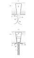
- the worker fixes the suspension bolt support fitting 1a to the upper space 8 of the slit 9a in the same manner as in the first embodiment. That is, the operator inserts the expansion member 5 and the widening member 6 of the suspension bolt support fitting 1a into the upper space 8 of the slit 9a and presses the shaft of the work tool 20 with the washer 3 pressed against the edge of the slit 9a.
- the widening member 6 By rotating the portion 21 with an electric tool or the like, the widening member 6 is moved downward along the male screw member 4, and the pair of expansion wall portions 5b and 5c are expanded to allow the suspension bolt support fitting 1a to be placed in the upper space. Fix to 8. At this time, as the widening member 6 moves downward along the male screw member 4, the torque when rotating the long nut 2 increases. And when the force which the pair of extended wall parts 5b and 5c press against the pair of wall parts 9b and 9c of the upper space 8 increases and the suspension bolt support fitting 1 is firmly fixed, the long nut 2 is rotated. The torque exceeds a predetermined value. At this time, as shown in FIG. 12, the breaking groove 31 formed in the long nut 2 is broken.
- the suspension bolt support fitting 1a of the present embodiment can indicate to the operator that the breaking groove 31 is broken and is firmly attached to the upper space 8 of the slit 9a. Therefore, there is no variation in tightening strength depending on the operator, and a stable construction state can be realized.
- the breaking groove 31 when the breaking groove 31 is broken, the tool mounting portion 30 of the long nut 2 is detached from the long nut 2 while being engaged with the engaging portion 22 of the working tool 20. At this time, the cap member 30 b is also detached from the long nut 2 together with the tool mounting portion 30. As a result, the lower surface of the long nut 2 is in a state in which the screw hole 2b for mounting the suspension bolt 7 is opened.
- the operator inserts the suspension bolt 7 into the screw hole 2b opened on the lower surface of the long nut 2 while rotating it.
- the tip of the suspension bolt 7 comes into contact with the flexible portion 42 of the deformable material 40 attached to the bottom of the screw hole 2 b and the suspension bolt 7 is further inserted, the flexible portion 42 of the deformable material 40 is attached to the suspension bolt 7. Since it is pressed by the tip, the tip 43 of the flexible part 42 appears outside the communication hole 2 c of the long nut 2.
- the tip 43 of the flexible portion 42 protrudes from the communication hole 2c by a predetermined length as shown in FIG. Become.
- the suspension bolt support fitting 1a of the present embodiment is not only excellent in work efficiency as in the first embodiment, but also suppresses variations in construction work by the operator and realizes a stable construction state. There is also an advantage of being able to.
- the cap member 30b is added to the lower surface of the long nut 2 when the breaking groove 31 is not broken, so that it is sufficient for the upper space 8 of the slit 9a.
- a member in which the long nut 2 and the male screw member 4 described above are integrally formed in advance may be used.
- suspension bolt support brackets 1, 1 a are brackets that support the suspension bolt 7 in a suspended state at the position where the slit 9 a is provided in the deck plate 9.
- the suspension bolt support fittings 1 and 1a described above cannot support the suspension bolt 7 in a state where it is suspended from a position where the slit 9a is not provided. Therefore, in the present embodiment, an example of a suspension bolt support bracket that can be attached in a state where the suspension bolt 7 is suspended at an arbitrary position on the lower surface of the deck plate 9 will be described.
- FIG. 15 is a perspective view showing each component member of the suspension bolt support fitting 60 according to the third embodiment of the present invention.
- the suspension bolt support bracket 60 is a bracket that is attached to the plurality of slits 9a of the deck plate 9 and can be supported in a state in which the suspension bolt 7 is suspended at an arbitrary position between the plurality of slits 9a.
- the suspension bolt support fitting 60 includes a suspension bolt support member 70 that can be attached to the lower surface of the deck plate 9 and to which the suspension bolt 7 can be attached.
- the suspension bolt support member 70 the deck plate 9 is supported by the rail member 65 that is longer than the interval at which the plurality of slits 9a are provided, and the position can be adjusted along the longitudinal direction of the rail member 65.
- the suspension bolt connecting member 67 to which the suspension bolt 7 can be attached is provided.
- the rail member 65 is made of, for example, C-shaped steel (lip groove shaped steel). That is, the rail member 65 includes a pair of top plates 65a, a pair of side plates 65b and 65b hanging from both sides of the top plate 65a, and a pair of side plates 65b and 65b bent inward.
- the long holes 65d and 65d extending in the longitudinal direction of the rail member 65 are provided at a plurality of locations on the top plate portion 65a.
- the plurality of long holes 65d, 65d are formed so that their center positions substantially coincide with the interval between the slits 9a of the deck plate 9. Further, the distance between the pair of flange portions 65c, 65c is formed larger than the diameter of the washer 3, for example.
- the suspension bolt connecting member 67 has a rectangular flat plate portion 67a and a nut portion 67b fixed to the center of the flat plate portion 67a.
- a through hole is provided in the center of the flat plate portion 67a, and the nut portion 67b is fixed coaxially with the through hole. Therefore, the suspension bolt connecting member 67 has a through screw hole penetrating vertically at a position where the nut portion 67b is fixed.
- One side of the flat plate portion 67a has a size smaller than the interval between the pair of side plate portions 65b and 65b of the rail member 65 and larger than the interval between the tips of the flange portions 65c and 65c facing each other.
- the suspension bolt connecting member 67 can be accommodated inside the rail member 65, and can be moved along the longitudinal direction of the rail member 65 while being accommodated inside the rail member 65. Further, the nut portion 67b has a female screw that is screwed with the suspension bolt 7, and the suspension bolt 7 can be attached thereto.
- the suspension bolt support fitting 60 includes a washer 3, a bolt 61, an expansion member 5, and a widening member 6. These members are arranged with respect to each of the plurality of long holes 65d, 65d provided in the rail member 65, and fix the rail member 65 to each of the plurality of slits 9a provided in the deck plate 9.
- the bolt 61 has a male screw member 61a and a bolt head 61b.
- the expansion member 5 and the widening member 6 are disposed above the long hole 65d provided in the rail member 65, and the washer 3 and the bolt 61 are attached to the rail member 65 from the lower side of the long hole 65d.
- the diameter of the washer 3 is larger than the width of the long hole 65d, when the male screw member 61a is inserted into the long hole 65d with the washer 3 attached to the male screw member 61a of the bolt 61, the rail member 65 The male screw member 61a protrudes upward.
- the expansion member 5 and the widening member 6 are attached to the protruding male screw member 61a.
- the mounting aspect of the expansion member 5 and the widening member 6 with respect to the male screw member 61a is the same as that of what was demonstrated in 1st Embodiment.
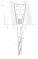
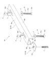
- FIG. 16 is a partially cutaway cross-sectional view showing a state where attachment of the suspension bolt 7 is completed using the suspension bolt support fitting 60.
- the suspension bolt support fitting 60 is fixed to the plurality of slits 9a. That is, the operator inserts the expansion member 5 and the widening member 6 attached to the male screw member 61a of the bolt 61 into the upper space 8 through the gap of the slit 9a, and the above-described working tool is inserted into the bolt head 61b of the bolt 61. 20 is attached and the bolt 61 is rotated.
- the bolt 61 is inserted into the elongated hole 65d, when the expansion member 5 and the widening member 6 are inserted into the upper space 8 from the gap of the slit 9a, the relative relationship between the expansion member 5 and the widening member 6 with respect to the rail member 65 is achieved. It is possible to adjust the position. Then, by rotating the bolt 61, the widening member 6 can be moved downward along the male screw member 61a. As a result, the widening member 6 pushes and expands the pair of expansion wall portions 5b and 5c of the expansion member 5 outward, so that the pair of expansion wall portions 5b and 5c urge the pair of wall portions 9b and 9c in the upper space 8 of the slit 9a. Fixed in a pressed state. The operator can fix the rail member 65 in a state where the rail member 65 is bonded to the lower surface of the deck plate 9 by performing the above-described operation on the bolts 61 provided in each of the plurality of slits 9a.
- the operator inserts the suspension bolt connecting member 67 attached to the tip of the suspension bolt 7 into the inside of the rail member 65 from the end of the rail member 65 fixed to the deck plate 9.
- the suspension bolt connecting member 67 is moved to the attachment position.
- the operator rotates the suspension bolt 7 so that the tip of the suspension bolt 7 contacts the top plate portion 65a of the rail member 65 as shown in FIG.
- the tip of the suspension bolt 7 comes into contact with the top plate portion 65 a and the suspension bolt 7 is further rotated, the tip of the suspension bolt 7 presses the top plate portion 65 a of the rail member 65.
- the axial force acting on the suspension bolt 7 tends to push the flat plate portion 67a of the suspension bolt connecting member 67 downward.
- the flat plate portion 67a is engaged with a pair of flange portions 65c and 65c provided on the rail member 65, and a strong frictional force is generated between the pair of flange portions 65c and 65c.
- the member 65 does not move in the longitudinal direction. That is, the suspension bolt connecting member 67 is fixed at a predetermined position of the rail member 65 by the axial force received from the suspension bolt 7. Accordingly, the suspension bolt 7 is also fixed so as not to move with respect to the longitudinal direction of the rail member 65.
- the rail member 65 and the suspension bolt connecting member 67 are used as the suspension bolt support member 70, so that the suspension bolt 7 is located at a position where the slit 9 a is not provided in the deck plate 9. Can be attached in a suspended state. Therefore, the suspension bolt support fitting 60 of this embodiment has a high degree of freedom when installing the suspension bolt 7 and is excellent in convenience.
- the rail member 65 was attached with respect to the two slits 9a adjacent in the deck plate 9 was illustrated, it is not restricted to this.
- the rail member 65 may be disposed across three or more slits 9a.
- the other configuration of the suspension bolt support fitting 60 in the present embodiment is the same as that described in the first embodiment.
- the deck plate 9 is relatively thick, and the strength is such that the pair of wall portions 9b and 9c are not deformed even before the ceiling slab S is placed. If it is a thing with high, you may make it perform the operation
- the widening member 6 is exemplified by a columnar metal fitting having a predetermined length arranged in the lateral direction.
- the widening member 6 is not necessarily limited to a cylindrical shape.
- the widening member 6 may have a semi-cylindrical shape, or may have a trapezoidal shape or an ingot-like shape.
- the widening member 6 is comprised as a nut member which has the through screw hole 6a, and when the front-end
- tip of 4 was illustrated.
- the widening member 6 is not necessarily limited to being provided as a member different from the male screw member 4 such as a nut member. That is, the widening member 6 may be provided integrally with the tip (upper end) of the male screw member 4 as the head of the male screw member 4.
- the widening member 6 is integrally provided as the head of the male screw member 4, it is necessary to lower the widening member 6 with the rotation of the long nut 2, so that the male screw member 4 and the long nut 2 Must be configured as a separate member.
- the lower end of the male screw member 4 is at least predetermined from the bottom of the screw hole 2a in a state where the members of the suspension bolt support fittings 1 and 1a are assembled. It is necessary to be in a state of floating by a distance.
- the predetermined distance in this case is set in advance according to the required amount of lowering of the widening member 6.
- the configuration described in the second embodiment described above in which the long nut 2 is provided with the communication hole 2c and the deformable member 40 is provided at the bottom of the screw hole 2b can also be applied to the first embodiment.
Landscapes
- Engineering & Computer Science (AREA)
- General Engineering & Computer Science (AREA)
- Mechanical Engineering (AREA)
- Architecture (AREA)
- Physics & Mathematics (AREA)
- Electromagnetism (AREA)
- Civil Engineering (AREA)
- Structural Engineering (AREA)
- Supports For Pipes And Cables (AREA)
Abstract
La présente invention a pour but d'améliorer l'efficacité du travail de fixation d'un boulon de suspension à une plaque de tablier ayant des fentes. Pour atteindre ce but, le support de boulon de suspension 1 est pourvu : d'un élément de vis mâle 4 inséré dans l'espace entre des fentes dans une plaque de tablier ; d'un élément d'expansion 5 qui est monté sur l'élément de vis mâle 4, et dans lequel une paire de parties de paroi d'expansion 5b, 5c sont disposées à un espacement inférieur à la largeur des fentes dans la plaque de tablier ; d'un élément d'élargissement 6 disposé au niveau de l'extrémité supérieure de l'élément de vis mâle 4, la partie inférieure de l'élément d'élargissement 6 étant disposée de façon à s'ajuster entre la paire de parties de paroi d'expansion 5b, 5c ; d'un élément de support de boulon de suspension 70 disposé sur la partie inférieure de l'élément de vis mâle 4 et relié à la surface inférieure de la plaque de tablier, rendant ainsi possible de fixer un boulon de suspension à l'élément de support de boulon de suspension 70.
Priority Applications (1)
| Application Number | Priority Date | Filing Date | Title |
|---|---|---|---|
| SG11201808793RA SG11201808793RA (en) | 2016-04-07 | 2017-03-30 | Hanging bolt support fitting |
Applications Claiming Priority (4)
| Application Number | Priority Date | Filing Date | Title |
|---|---|---|---|
| JP2016077025 | 2016-04-07 | ||
| JP2016-077025 | 2016-04-07 | ||
| JP2016-182622 | 2016-09-20 | ||
| JP2016182622A JP6829864B2 (ja) | 2016-04-07 | 2016-09-20 | 吊りボルト支持金具 |
Publications (1)
| Publication Number | Publication Date |
|---|---|
| WO2017175659A1 true WO2017175659A1 (fr) | 2017-10-12 |
Family
ID=60001240
Family Applications (1)
| Application Number | Title | Priority Date | Filing Date |
|---|---|---|---|
| PCT/JP2017/013296 Ceased WO2017175659A1 (fr) | 2016-04-07 | 2017-03-30 | Support de boulon de suspension |
Country Status (1)
| Country | Link |
|---|---|
| WO (1) | WO2017175659A1 (fr) |
Cited By (2)
| Publication number | Priority date | Publication date | Assignee | Title |
|---|---|---|---|---|
| GB2566707A (en) * | 2017-09-21 | 2019-03-27 | Clive Michell Andrew | Securing mechanism |
| EP4530417A1 (fr) | 2023-09-27 | 2025-04-02 | CDM Stravitec NV | Système de fixation pour rainure en queue d'aronde |
Citations (4)
| Publication number | Priority date | Publication date | Assignee | Title |
|---|---|---|---|---|
| JPH09189316A (ja) * | 1995-11-10 | 1997-07-22 | Alps Seiko Kk | 建築用ブラインドボルト |
| JP2809584B2 (ja) * | 1993-12-13 | 1998-10-08 | 光洋器材株式会社 | デッキプレート用インサート |
| JPH10325206A (ja) * | 1997-05-27 | 1998-12-08 | Morii:Kk | 吊金具 |
| JP4492900B2 (ja) * | 2000-08-10 | 2010-06-30 | 株式会社国元商会 | デッキプレート用天井吊り金具 |
-
2017
- 2017-03-30 WO PCT/JP2017/013296 patent/WO2017175659A1/fr not_active Ceased
Patent Citations (4)
| Publication number | Priority date | Publication date | Assignee | Title |
|---|---|---|---|---|
| JP2809584B2 (ja) * | 1993-12-13 | 1998-10-08 | 光洋器材株式会社 | デッキプレート用インサート |
| JPH09189316A (ja) * | 1995-11-10 | 1997-07-22 | Alps Seiko Kk | 建築用ブラインドボルト |
| JPH10325206A (ja) * | 1997-05-27 | 1998-12-08 | Morii:Kk | 吊金具 |
| JP4492900B2 (ja) * | 2000-08-10 | 2010-06-30 | 株式会社国元商会 | デッキプレート用天井吊り金具 |
Cited By (4)
| Publication number | Priority date | Publication date | Assignee | Title |
|---|---|---|---|---|
| GB2566707A (en) * | 2017-09-21 | 2019-03-27 | Clive Michell Andrew | Securing mechanism |
| EP4530417A1 (fr) | 2023-09-27 | 2025-04-02 | CDM Stravitec NV | Système de fixation pour rainure en queue d'aronde |
| BE1032019A1 (nl) | 2023-09-27 | 2025-04-23 | Cdm Stravitec | Bevestigingssysteem voor in een zwaluwstaartgroef |
| BE1032019B1 (nl) * | 2023-09-27 | 2025-04-29 | Cdm Stravitec | Bevestigingssysteem voor in een zwaluwstaartgroef |
Similar Documents
| Publication | Publication Date | Title |
|---|---|---|
| TWI451025B (zh) | 具有展開突耳的螺帽 | |
| US8181419B1 (en) | Connector for connecting building members | |
| EP3208398B1 (fr) | Élément de base pour un ensemble d'ancrage et procédé d'utilisation | |
| EP1260408A2 (fr) | Fixation de poignée auxiliaire pour garniture modulaire de toit pour véhicule | |
| US20110318134A1 (en) | Anchor | |
| KR101912025B1 (ko) | 하단 부재의 고정 장치 및 이것을 구비한 유체 제어 장치 | |
| EP2538000B1 (fr) | Procédé permettant de corriger l'ovalisation dans des tours de turbine éolienne | |
| JP5234908B2 (ja) | 床パネルの支持構造 | |
| JP2020056464A (ja) | 支持装置及びそれを用いた施工方法 | |
| WO2017175659A1 (fr) | Support de boulon de suspension | |
| JP6764667B2 (ja) | 安全柵土台 | |
| JP6246575B2 (ja) | あと施工アンカー、アンカー施工具および施工方法 | |
| KR101591391B1 (ko) | 건물외장재 고정구조 | |
| JP2010203048A (ja) | 支柱取り付け構造 | |
| JP2017190660A (ja) | 吊りボルト支持金具 | |
| KR20130129151A (ko) | 건설용 시스템서포트의 클램프 | |
| KR20190098408A (ko) | 거푸집용 선시공 타입 볼트 어셈블리 | |
| JP6261346B2 (ja) | パネルの取付け構造 | |
| JP7323920B2 (ja) | 天井設置金具 | |
| JP2017078301A (ja) | ブレース連結金具の施工方法 | |
| KR102813717B1 (ko) | 직립 체결이 가능한 l형 볼트 체결 구조 | |
| JP2017179840A (ja) | 吊りボルト支持金具及びその施工方法 | |
| JP7587837B2 (ja) | 板状ワーク積層体へのピアスナットの結合方法 | |
| KR102469674B1 (ko) | 천장용 패널 어셈블리 | |
| JP6254932B2 (ja) | 偏心スペーサーおよび柱脚固定構造 |
Legal Events
| Date | Code | Title | Description |
|---|---|---|---|
| NENP | Non-entry into the national phase |
Ref country code: DE |
|
| 121 | Ep: the epo has been informed by wipo that ep was designated in this application |
Ref document number: 17779038 Country of ref document: EP Kind code of ref document: A1 |
|
| 122 | Ep: pct application non-entry in european phase |
Ref document number: 17779038 Country of ref document: EP Kind code of ref document: A1 |