WO2017175672A1 - Actionneur rotatif à axe unique - Google Patents
Actionneur rotatif à axe unique Download PDFInfo
- Publication number
- WO2017175672A1 WO2017175672A1 PCT/JP2017/013530 JP2017013530W WO2017175672A1 WO 2017175672 A1 WO2017175672 A1 WO 2017175672A1 JP 2017013530 W JP2017013530 W JP 2017013530W WO 2017175672 A1 WO2017175672 A1 WO 2017175672A1
- Authority
- WO
- WIPO (PCT)
- Prior art keywords
- holder
- diffraction grating
- actuator
- light
- rotating shaft
- Prior art date
- Legal status (The legal status is an assumption and is not a legal conclusion. Google has not performed a legal analysis and makes no representation as to the accuracy of the status listed.)
- Ceased
Links
Images

















Classifications
-
- G—PHYSICS
- G02—OPTICS
- G02B—OPTICAL ELEMENTS, SYSTEMS OR APPARATUS
- G02B26/00—Optical devices or arrangements for the control of light using movable or deformable optical elements
- G02B26/08—Optical devices or arrangements for the control of light using movable or deformable optical elements for controlling the direction of light
- G02B26/0808—Optical devices or arrangements for the control of light using movable or deformable optical elements for controlling the direction of light by means of one or more diffracting elements
-
- G—PHYSICS
- G01—MEASURING; TESTING
- G01J—MEASUREMENT OF INTENSITY, VELOCITY, SPECTRAL CONTENT, POLARISATION, PHASE OR PULSE CHARACTERISTICS OF INFRARED, VISIBLE OR ULTRAVIOLET LIGHT; COLORIMETRY; RADIATION PYROMETRY
- G01J3/00—Spectrometry; Spectrophotometry; Monochromators; Measuring colours
- G01J3/02—Details
- G01J3/0202—Mechanical elements; Supports for optical elements
-
- G—PHYSICS
- G01—MEASURING; TESTING
- G01J—MEASUREMENT OF INTENSITY, VELOCITY, SPECTRAL CONTENT, POLARISATION, PHASE OR PULSE CHARACTERISTICS OF INFRARED, VISIBLE OR ULTRAVIOLET LIGHT; COLORIMETRY; RADIATION PYROMETRY
- G01J3/00—Spectrometry; Spectrophotometry; Monochromators; Measuring colours
- G01J3/02—Details
- G01J3/0205—Optical elements not provided otherwise, e.g. optical manifolds, diffusers, windows
- G01J3/021—Optical elements not provided otherwise, e.g. optical manifolds, diffusers, windows using plane or convex mirrors, parallel phase plates, or particular reflectors
-
- G—PHYSICS
- G01—MEASURING; TESTING
- G01J—MEASUREMENT OF INTENSITY, VELOCITY, SPECTRAL CONTENT, POLARISATION, PHASE OR PULSE CHARACTERISTICS OF INFRARED, VISIBLE OR ULTRAVIOLET LIGHT; COLORIMETRY; RADIATION PYROMETRY
- G01J3/00—Spectrometry; Spectrophotometry; Monochromators; Measuring colours
- G01J3/02—Details
- G01J3/0291—Housings; Spectrometer accessories; Spatial arrangement of elements, e.g. folded path arrangements
-
- G—PHYSICS
- G01—MEASURING; TESTING
- G01J—MEASUREMENT OF INTENSITY, VELOCITY, SPECTRAL CONTENT, POLARISATION, PHASE OR PULSE CHARACTERISTICS OF INFRARED, VISIBLE OR ULTRAVIOLET LIGHT; COLORIMETRY; RADIATION PYROMETRY
- G01J3/00—Spectrometry; Spectrophotometry; Monochromators; Measuring colours
- G01J3/02—Details
- G01J3/06—Scanning arrangements arrangements for order-selection
-
- G—PHYSICS
- G01—MEASURING; TESTING
- G01J—MEASUREMENT OF INTENSITY, VELOCITY, SPECTRAL CONTENT, POLARISATION, PHASE OR PULSE CHARACTERISTICS OF INFRARED, VISIBLE OR ULTRAVIOLET LIGHT; COLORIMETRY; RADIATION PYROMETRY
- G01J3/00—Spectrometry; Spectrophotometry; Monochromators; Measuring colours
- G01J3/02—Details
- G01J3/10—Arrangements of light sources specially adapted for spectrometry or colorimetry
-
- G—PHYSICS
- G01—MEASURING; TESTING
- G01J—MEASUREMENT OF INTENSITY, VELOCITY, SPECTRAL CONTENT, POLARISATION, PHASE OR PULSE CHARACTERISTICS OF INFRARED, VISIBLE OR ULTRAVIOLET LIGHT; COLORIMETRY; RADIATION PYROMETRY
- G01J3/00—Spectrometry; Spectrophotometry; Monochromators; Measuring colours
- G01J3/12—Generating the spectrum; Monochromators
- G01J3/18—Generating the spectrum; Monochromators using diffraction elements, e.g. grating
-
- G—PHYSICS
- G01—MEASURING; TESTING
- G01J—MEASUREMENT OF INTENSITY, VELOCITY, SPECTRAL CONTENT, POLARISATION, PHASE OR PULSE CHARACTERISTICS OF INFRARED, VISIBLE OR ULTRAVIOLET LIGHT; COLORIMETRY; RADIATION PYROMETRY
- G01J3/00—Spectrometry; Spectrophotometry; Monochromators; Measuring colours
- G01J3/28—Investigating the spectrum
- G01J3/30—Measuring the intensity of spectral lines directly on the spectrum itself
- G01J3/32—Investigating bands of a spectrum in sequence by a single detector
-
- G—PHYSICS
- G01—MEASURING; TESTING
- G01J—MEASUREMENT OF INTENSITY, VELOCITY, SPECTRAL CONTENT, POLARISATION, PHASE OR PULSE CHARACTERISTICS OF INFRARED, VISIBLE OR ULTRAVIOLET LIGHT; COLORIMETRY; RADIATION PYROMETRY
- G01J3/00—Spectrometry; Spectrophotometry; Monochromators; Measuring colours
- G01J3/02—Details
- G01J3/06—Scanning arrangements arrangements for order-selection
- G01J2003/064—Use of other elements for scan, e.g. mirror, fixed grating
Definitions
- the present invention relates to a uniaxial rotary actuator for rotationally driving an optical element such as a diffraction grating in a uniaxial direction.
- the wavelength of light reaching the slit is changed by rotating the diffraction grating by an actuator.
- an actuator a stepping motor, a sine bar mechanism, and the like are often used.
- Patent Document 1 discloses a small mirror tilt actuator that can drive a mirror with high accuracy by magnetically driving a mirror held on a base via a leaf spring using a coil, a magnet, and a yoke. .
- the conventional monochromator using a stepping motor or a sine bar mechanism is not suitable for miniaturization. That is, the stepping motor is relatively large, and further, when the rotational resolution of the stepping motor does not satisfy the spectral performance of the monochromator, a reduction gear (gear) is required, and therefore the size is further increased.
- the sine bar mechanism requires a lead screw and is therefore large and not suitable for miniaturization.
- the actuator of Patent Document 1 since the actuator of Patent Document 1 has a large number of parts to be assembled, assembling is complicated by that amount, and if the assembly accuracy is poor, the driving accuracy is also deteriorated, so that high assembly accuracy is required. it is conceivable that. That is, labor and time for assembling many parts with high accuracy are required. Furthermore, although the actuator of Patent Document 1 can be driven in a single axis direction, it is basically configured to be driven in a biaxial direction. It is thought that these are likely to occur.
- An object of the present invention is to provide a small and highly accurate single-axis rotary actuator suitable for rotationally driving an optical element such as a diffraction grating in the single-axis direction.
- Another object of the present invention is to provide a uniaxial rotary actuator suitable for forming light having a wide wavelength range.
- One aspect of the single-axis rotary actuator of the present invention is: A holder having a placement surface to which the optical element is attached, and a rotation axis parallel to the placement surface; A fixed part having a bearing for holding the rotating shaft of the holder; An elastic member comprising an outer peripheral portion fixed to the fixing portion, an inner peripheral portion fixed to the holder, and an elastic arm portion connecting the outer peripheral portion and the inner peripheral portion; A drive unit having a coil provided in the holder and a magnet provided in the fixing unit, and rotating the holder around the rotation axis; Comprising The optical element has a length in the axial direction of the rotary shaft that is longer than a length in a direction orthogonal to the axial direction of the rotary shaft.
- the present invention it is possible to realize a small and highly accurate single-axis rotary actuator suitable for rotationally driving an optical element such as a diffraction grating in the single-axis direction.
- an optical element such as a diffraction grating
- the length of the axis of rotation of the optical element longer than the length of the direction perpendicular to the axis of the axis of rotation, light from multiple light sources can be simultaneously diffracted, and the wavelength range
- a single-axis rotary actuator suitable for forming a wide light can be realized.
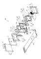
- FIG. 1 is an exploded perspective view of the actuator of FIG.
- FIGS. 1 and 2 Diagram for explaining the direction of the magnetic force generated by the actuator, the direction of the current, the direction of the Lorentz force, and the rotational moment
- 9A to 9C are diagrams showing the rotation state of the holder (diffraction grating).
- 10A to 10C are diagrams for explaining the rotational position detection using the optical sensor and the reflecting plate.
- FIG. 11A is a diagram showing a configuration example of the optical sensor
- FIG. 11B is a graph showing the relationship between the distance from the optical sensor to the reflector and the output current ratio.
- FIGS. 12A to 12C are diagrams for explaining rotational position detection using an optical sensor and a reflecting plate when two optical sensors are provided.
- the figure which shows the relationship between the rotation angle and sensor output when two optical sensors are provided Graph showing the torque generated by the actuator of the embodiment
- the top view which shows the structural example of the spectrometer using the actuator of embodiment
- the figure which shows schematic structure of the optical system in which the 1 axis
- the perspective view which shows the whole structure of the 1 axis
- FIG. 23 is an exploded perspective view of the actuator of FIG. The figure which shows the mode of the light which injects into the diffraction grating of Embodiment 2.
- FIG. 28A is a figure which shows the state which attached the rotating shaft to the holder
- FIG. 28B is a figure which shows the state before attaching the rotating shaft of a holder.
- FIG. 29A is a view showing a state where the rotation shaft is displaced as a result of molding
- FIG. 29B is a view showing a state where one of the rotation shafts is detached from the bearing
- FIG. 29A is a view showing a state where the rotation shaft is displaced as a result of molding
- FIG. 29B is a view showing a state where one of the rotation shafts is detached from the bearing
- FIG. 29A is a view showing a state where the rotation shaft is displaced as a result of molding
- FIG. 29B is a view showing a state where one of the rotation shafts is detached from the bearing
- 29C is a state where one of the rotation shafts is rotated while shaking in the bearing.
- Figure showing Diagram for explaining the attachment of the rotating shaft to the holder The figure which shows the mode of the electrical connection of the leaf
- a perspective view showing a cantilever structure using a ball bearing Partial sectional view showing a cantilever structure using a ball bearing
- FIG. 1 is a perspective view showing an overall configuration of a single-axis rotary actuator 100 (hereinafter simply referred to as “actuator”) according to Embodiment 1 of the present invention
- FIG. 2 is an exploded perspective view of the actuator 100.
- the actuator 100 is configured to change the wavelength of light reaching the slit (not shown) via the diffraction grating 1 according to the rotation angle of the diffraction grating 1 by rotationally driving the diffraction grating 1 in one axis direction. It has become.
- an application example of the actuator 100 shown in FIG. 1 to the spectroscope will be described later with reference to FIG.
- the direction of the reflective surface of the diffraction grating 1 is the front surface direction
- the direction opposite to the reflective surface is the back surface direction.
- the actuator 100 includes a fixed angle 2, a base 3, a magnet 10, a fixed portion 20, a leaf spring 30, a coil 40, a holder 50, a spacer 60, a cover 70, The optical sensor 80 and the flexible printed circuit board 90 are provided.
- the fixed angle 2 has a substantially L-shaped cross-section, and each part of the actuator 100 is attached to the front surface, and the lower surface is fixed to a predetermined fixed surface. Thereby, the actuator 100 is attached to a predetermined surface via the fixed angle 2.
- the fixing unit 20 includes a frame body 21 and a yoke 22 that holds the magnet 10.
- the frame body 21 is formed with a concave bearing 21 a that holds the rotating shaft 52 of the holder 50.
- the yoke 22 has a U-shaped cross-sectional shape and is fitted to the frame body 21 while holding the magnet 10.
- the fixed portion 20 is attached to the fixed angle 2 via the base 3.
- the magnet 10 includes two magnets 11 and 12 that are attached to the bottom surface of the yoke 22 at a predetermined interval, and two magnets 13 and 14 that are attached to face the side surface of the yoke 22.
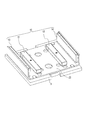
- the attachment state of the magnet 10 to the yoke 22 is shown in FIG.
- the magnets 11 and 12 are attached to the yoke 22 so that the south pole faces the yoke 22 side and the north pole faces the surface side.
- the magnets 13 and 14 are attached to the yoke 22 so that the north pole faces the yoke side and the south pole faces the surface side, that is, the south poles face each other.
- all the N poles and S poles may be reverse to FIG.
- the magnets 11 and 12 are attached to the yoke 22 such that the N pole faces the yoke 22 side and the S pole faces the surface side, and the magnets 13 and 14 have the S pole facing the yoke side and the N side facing the surface side.
- You may attach to the yoke 22 so that a pole may face, ie, N poles may face each other.
- the outer shape of the frame body 21 is substantially square, and a leaf spring 30 is attached to the edge of the frame body 21. Further, the holder 50 and the coil 40 fixed to the holder 50 are disposed in the hollow portion of the frame body 21.
- the leaf spring 30 includes an outer peripheral portion 31 fixed to the frame body 21 of the fixing portion 20, an inner peripheral portion 32 fixed to the holder 50, and the outer peripheral portion 31 and the inner peripheral portion 32. And an arm portion 33 having elasticity to connect the two.
- the holder 50 includes a holder main body 51 whose outer shape is a substantially square shape, a rotating shaft 52 projecting up and down from the holder main body 51, and a reflecting plate 53 attached to the rotating shaft 52.
- a mounting surface for mounting the diffraction grating 1 is formed on the surface side of the holder body 51, and the diffraction grating 1 is fixed to the mounting surface by adhesion.
- the diffraction grating 1 is bonded to the mounting surface of the holder main body 51 together with the spacer 60 in a state where the diffraction grating 1 is positioned by being fitted into the opening 61 of the spacer 60.
- the reflection plate 53 is arranged so that the main surface is on a surface obtained by extending the main surface of the holder main body 51.
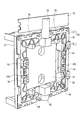
- FIG. 4 shows a state in which the leaf spring 30 and the holder 50 are attached to the frame body 21.
- the outer peripheral portion 31 of the leaf spring 30 is fixed to the edge portion of the frame body 21.
- the holder main body 51 is disposed in the hollow portion of the frame body 21.
- the rotating shaft 52 is pivotally supported by the bearing 21 a of the frame body 21, so that the holder 50 is rotatable about the rotating shaft 52.
- the protrusion 54 of the holder 50 is fitted to the inner peripheral portion 32 of the leaf spring 30.
- the holder 50 is rotatable about the rotation shaft 52 and is urged by the leaf spring 30 to return to the neutral position as shown in FIG.
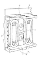
- the coil 40 is attached to the back side of the holder body 51. This state is shown in FIG.
- Two air-core coils 41 and 42 are fixed to the back surface of the holder body 51 at a predetermined interval. As indicated by the arrows in the figure, currents in opposite directions flow through the coils 41 and 42. Specifically, in FIG. 5, a clockwise current flows through the coil 41, and a counterclockwise current flows through the coil 42.
- the leaf spring 30 is made of a highly conductive material such as metal, and power is supplied to the coil 40 via the leaf spring 30.
- a power feeding portion (not shown) of the flexible printed circuit board 90 is connected to the outer peripheral portion 31 of the leaf spring 30, and the coil 41, 42 terminals 40a and 40b are connected.
- the inner peripheral portion 32 and the terminals 40a and 40b are soldered.
- power can be supplied from the flexible printed circuit board 90 to the coil 40, which is a movable part, via the leaf spring 30.
- the leaf spring 30 also has a power feeding function, the power feeding system can be simplified, and the downsizing of the apparatus can be promoted.
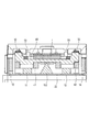
- FIG. 6 is a cross-sectional view taken along the line A-A ′ of FIGS. 1 and 2 (during assembly) taken along a line passing through the center of the diffraction grating 1.
- an air core coil 41 is disposed above the rectangular magnet 11
- an air core coil 42 is disposed above the rectangular magnet 12.
- the magnet 13 is disposed on the side of the coil 41
- the magnet 14 is disposed on the side of the coil 42.
- FIG. 9 described later, when the holder 50 rotates, the magnets 11 and 12 alternately enter the air core portions of the air core coils 41 and 42.
- the magnets 11 and 12 are provided on the air-core portions of the air-core coils 41 and 42 in a state where the rotation angle is 0 ° as shown in FIG. It is arranged slightly shifted from the center to the rotating shaft side.
- FIG. 7 shows the direction of the magnetic force M0, the direction of the current, the direction of the Lorentz force L0, and the rotational moment M1 generated in the actuator 100.
- a magnetic force M0 is generated from the magnet 11 on the bottom surface of the yoke 22 toward the magnet 13 on the side surface of the yoke 22, and a magnetic force M0 is generated from the magnet 12 on the bottom surface of the yoke 22 toward the magnet 14 on the side surface of the yoke 22. Further, a magnetic force M0 is generated from the magnets 11 and 12 toward the center of the yoke 22.
- a Lorentz force L0 is generated in the coils 41 and 42 according to the magnetic force M0 and the direction of the current flowing in the coils 41 and 42.
- the magnets 13 and 14 are provided on the side surface of the yoke 22. As a result, it is possible to improve torque and reduce power consumption. Further, by providing the magnets 13 and 14 on the side surface of the yoke 22, it is possible to generate a strong magnetic force particularly at a position far from the rotation axis, whereby the coils 41 and 42 have a strong Lorentz force L0 at a position far from the rotation axis. Can be obtained. As a result, a large rotational moment M1 can be obtained efficiently.
- a configuration in which the magnets 13 and 14 are not provided may be employed. In this case, there is a demerit that the torque is reduced and the power consumption is increased as compared with the case where the magnets 13 and 14 are provided, but there is an advantage that the size can be reduced because the size is reduced.
- FIG. 8 shows the relationship between the current value passed through the coils 41 and 42 and the rotation angle of the holder 50 (diffraction grating 1).
- the holder 50 (diffraction grating 1) rotates to a position where the rotational moment corresponding to the current value flowing through the coils 41 and 42 and the urging force of the leaf spring 30 are balanced.
- a certain rotation angle is reached (6.5 ° in the example of FIG. 8)
- the projection 55 of the holder 50 abuts against the back surface of the cover 70 and the rotation of the holder 50 stops.
- the rotation of the holder 50 is regulated by the cover 70, the rotation can be regulated not only by electrical rotation control but also mechanically, so that rotation exceeding a predetermined range can be ensured. Can be prevented.
- the rotating shaft 52 is covered with the cover 70 (FIG. 1), it is possible to prevent the holder 50 from being removed.
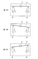
- FIG. 9 is a view showing a rotation state of the holder 50 (diffraction grating 1).
- FIG. 9A shows a state in which no current flows through the coils 41 and 42, and the holder 50 (diffraction grating 1) is neutral (that is, the rotation angle is 0 °) by the urging force of the leaf spring 30.
- FIG. 9B shows a state in which a current in the direction shown in FIG. 7 is passed through the coils 41 and 42, and the holder 50 (diffraction grating 1) is rotated in the clockwise direction in the figure.
- FIG. 9C shows a state in which a current in the direction opposite to the direction shown in FIG.
- the holder 50 (diffraction grating 1) is rotated counterclockwise in the figure. Is done.
- the holder 50 (diffraction grating 1) can be driven to rotate clockwise and counterclockwise around the neutral position of FIG. 9A by changing the direction of the current supplied by the coils 41 and 42. ing.
- the rotational position of the holder 50 (diffraction grating 1) is detected by the optical sensor 80 attached to the fixed angle 2, and the detection result is sent to the control unit (not shown) via the flexible printed board 90.
- the control unit controls the rotation of the holder 50 (diffraction grating 1) by supplying a current value corresponding to the detection result to the coils 41 and 42 via the flexible printed circuit board 90.
- the optical sensor 80 irradiates light toward the reflecting plate 53, and detects the rotational position by detecting the light quantity of the reflected light. It has become. That is, the closer the distance from the optical sensor 80 to the reflecting plate 53, the larger the amount of reflected light, so that the rotational position can be determined based on the amount of light.
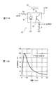
- FIG. 11A shows a configuration example of the optical sensor 80.
- the optical sensor 80 emits light by a light emitting diode 81, receives light reflected from a reflecting plate by a phototransistor 82, and obtains an output current corresponding to the amount of reflected light.
- FIG. 11B is a graph showing the relationship between the distance from the optical sensor 80 to the reflecting plate 53 and the output current ratio (the output current when the maximum amount of light is obtained is 100%).
- the rotational position is detected by one optical sensor 80.
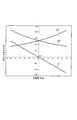
- the optical sensor 80 is positioned at both the left and right positions around the rotation shaft 52. , 180 may be provided. Then, as shown in FIG. 13, by taking the difference between the sensor outputs L80 and L180 obtained by these optical sensors 80 and 180, a linear sensor output L1 can be obtained.
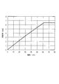
- FIG. 14 is a graph showing the torque generated by the actuator 100 of the present embodiment.
- FIG. 14 shows the torque generated particularly when a current having a direction as shown in FIG. 7 is supplied.
- the torque of the coil 41 rotating away from the magnet 11 decreases as the rotation angle increases, while the torque of the coil 42 rotating toward the magnet 12 increases as the rotation angle increases. Therefore, the decrease in the torque of the coil 41 rotating away from the magnet 11 is compensated by the increase in the torque of the coil 42 rotating toward the magnet 12. As a result, the total torque does not decrease drastically even when the rotation angle increases, and becomes almost flat.
- the rotatable range of the holder 50 (diffraction grating 1) is ⁇ 6.5 ° to + 6.5 °, and a substantially flat torque is generated in this rotatable range.
- the rotatable range is not limited to this, and the rotation range may be ⁇ 6.5 ° or more.
- the protrusion 55 of the holder 50 is lowered, the holder 50 rotates more greatly.
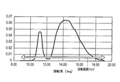
- FIG. 15 shows a spectrum when white light is dispersed by rotating the diffraction grating 1 having a grating pitch of 1.5 ⁇ m.
- FIG. 15 shows that if the diffraction grating 1 can be rotated by 10.3 ° or more, it is possible to diffract the entire visible light region.
- the actuator 100 according to the present embodiment can rotate the diffraction grating 1 in a range of ⁇ 6.5 ° to + 6.5 °, that is, 13 °, and can diffract the entire visible light range. It is.
- the holder 50 having the mounting surface to which the diffraction grating 1 is attached and the rotary shaft 52, and the fixed portion 20 having the bearing 21 a that holds the rotary shaft 52 of the holder 50.
- an elastic member comprising an outer peripheral portion 31 fixed to the fixing portion 20, an inner peripheral portion 32 fixed to the holder 50, and an outer peripheral portion 31 and an elastic arm portion 33 connecting the inner peripheral portion 32.
- a drive unit having the coil 40 provided in the holder 50 and the magnet 10 provided in the fixed unit 20, so that the optical element such as the diffraction grating 1 is rotationally driven in one axial direction.
- a suitable small-sized and highly accurate single-axis rotary actuator 100 can be realized.
- the diffraction grating 1 can be stopped at an arbitrary angle, an arbitrary wavelength component in the incident light can be extracted. That is, if the incident light is white, components such as blue, green, and red can be extracted according to the angle at which the diffraction grating 1 is stopped, so that it can also be used as a wavelength tunable light source.
- the air core duplex coils 41 and 42 are arranged so as to be fitted on the back surface of the holder 50 and the magnets 11 and 12 are inserted into the air core portions of the coils 41 and 42, the magnetic efficiency is high and the XY size is obtained. 1 axis rotation actuator 100 with small can be realized.
- the diffraction grating 1 can be attached only to the mounting surface of the holder 50, the diffraction grating 1 having various shapes can be easily applied. Actually, by using the spacer 60 in which the opening 61 corresponding to the shape of the diffraction grating 1 is formed, the diffraction grating 1 having various sizes and shapes can be easily handled.
- the apparatus can be downsized as compared with the case where a rotary encoder or the like is used.
- the configuration for detecting the angle is not limited to this.
- a rotary encoder may be used, a Hall element may be used, and the angle may be detected by detecting the drive current with a shunt resistor. Further, the angle may be detected by measuring the inductance of the coils 41 and 42. In other words, when the rotation angle changes, the magnetic flux passing through the coils 41 and 42 changes and the inductance varies, so that the angle can be detected by measuring this inductance.
- a rotation angle may be detected by providing a detection coil in addition to the drive coil and measuring an induced electromotive force generated in the detection coil.
- the optical sensor may be stored inside the actuator.
- the yoke 22 has a U-shaped cross section.
- the shape of the yoke is not limited to this.
- the shape of the yoke may be as shown in FIG. 16, for example. That is, the yoke 122 may have a shape having a convex portion at the center. Thereby, since the magnetic flux in the vicinity of the convex portion can be strengthened, a larger rotational torque can be generated.
- the configuration of the coil, yoke, and magnet is not limited to the configuration of the above-described embodiment, and may be, for example, a configuration as shown in FIG.
- one air-core coil 140 is provided on the back side of the holder 50, and first and second yokes 222-1 and 222-2 are provided so as to sandwich the air-core coil 140. It has been.
- Magnets 13 and 14 are provided on the first and second yokes 222-1 and 222-2, respectively.
- the holder 50 (diffraction grating 1) can be rotated by passing an electric current through the coil 140.
- the shape of the grating groove of the diffraction grating 1 attached to the holder 50 can be a rectangular shape, a sawtooth shape, a sine wave shape, or the like.
- the diffraction grating 1 attached to the holder 50 may have a concave reflecting surface.
- a transmissive type may be used as the diffraction grating 1.
- an opening or notch for allowing the light transmitted through the diffraction grating 1 to pass through may be formed in the holder 50 or the yoke 22.
- a fulcrum member 152 is provided on the lower side (back side) of the position serving as the rotation axis of the holder 50, and the fulcrum member 152 causes the holder 50 to resist the urging force of the leaf spring 30. You may make it hold
- FIG. 19 is a plan view showing the configuration of the spectroscope 200 using the actuator 100 of the above-described embodiment.
- Light L1 emitted from an optical unit (not shown) enters the diffraction grating 1 attached to the actuator 100 via the reflection mirror 201.
- the light diffracted by the diffraction grating 1 is directed to the slit portion 203 provided with a slit (not shown) via the reflection mirror 202.
- the light dispersed by passing through the slit is emitted from the light outlet 204.
- This dispersed light can be used as light for measuring biological information such as urine components and blood components.
- the actuator 100 can rotationally drive the diffraction grating 1 without resonating at 70 to 80 Hz, so that biological information such as urine components and blood components can be measured in a short time.
- the spectral performance suitable for this can be realized.
- the optical element attached to the holder 50 is not limited to the diffraction grating 1, and for example, a mirror or the like may be attached.
- the actuator 100 according to the above-described embodiment is not limited to the actuator of the spectroscope, and can be used as an actuator such as a rotation mechanism for changing the light distribution of the headlight for an automobile, for example.
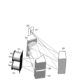
- FIG. 20 is a diagram showing a schematic configuration of an optical system in which the uniaxial rotary actuator of the present embodiment is used.
- the optical system in FIG. 20 includes two light sources 311 and 312 having different wavelengths.
- the light from the light source 311 is reflected by the collimator mirror 321 to be collimated and then incident on the diffraction grating 401.
- the light from the light source 312 is reflected by the collimator mirror 322 to be collimated and then incident on the diffraction grating 401.
- the light from the two light sources 311 and 312 is incident on the diffraction grating 401 at the same incident angle.
- the collimating mirrors 321 and 322 for example, off-axis parabolic mirrors may be used.
- the diffraction grating 401 is rotationally driven by a uniaxial rotary actuator of the present embodiment described later.
- the outgoing light from the rotating grating 401 is condensed at the position of the slit 341 formed in the slit part 340 by the focus mirror 330.
- the focus mirror 330 for example, a single off-axis parabolic mirror may be used.
- the light from any light source can be put into one fiber by setting the divergence angle of the condensed light beam to be equal to or less than the NA (Numerical Aperture) of the fiber. , Improve convenience.
- the wavelength range can be expanded, and it is possible to cope with spectroscopic measurement in a wide wavelength range.
- the intensity of the overlapping wavelengths can be increased, and the S / N can be improved.
- ⁇ is an incident angle to the diffraction grating 401
- ⁇ is an emission angle from the diffraction grating 401
- m is a diffraction order
- ⁇ is a wavelength
- p is a grating pitch of the diffraction grating 401.
- the wavelength emitted from the slit 341 can be changed by rotating the diffraction grating 401 by a single-axis rotary actuator.
- FIG. 22 is a diagram showing this state.
- wavelengths corresponding to the stop angle three wavelengths in the example of FIG. 22
- a continuous spectrum can be obtained.
- the two light sources 311 and 312 are used, but three or more light sources may be used.
- three collimating mirrors, one diffraction grating, and one focus mirror may be used.
- the collimating mirror and the focus mirror may be constituted by lenses.
- the diffraction grating 401 may be a transmission type.
- a spherical mirror, a toroidal mirror, an aspherical mirror, or the like can be used as the collimating mirror and the focus mirror.
- a pre-spectral method in which a measurement target (cell or the like) and a light receiving element are arranged after the diffraction grating 401 and the slit 341 is assumed.
- the configuration in FIG. It can also be used in a post-spectral method in which a target (cell or the like) is arranged and a light receiving element is installed after the slit 341. If a light receiving element is arranged after the slit 341, a single light receiving element can be used, so that the cost can be reduced.
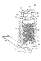
- FIG. 23 is a perspective view showing an overall configuration of a uniaxial rotary actuator 500 (hereinafter also simply referred to as “actuator”) according to the second embodiment
- FIG. 24 is an exploded perspective view of the actuator 500.
- the actuator 500 rotates the diffraction grating 401 in one axial direction so that the wavelength of light reaching the slit 341 (FIG. 20) via the diffraction grating 401 is changed according to the rotation angle of the diffraction grating 401. It has become.
- the actuator 500 includes a fixed angle 502 (corresponding to the fixed angle 2 in FIG. 2), a base 503 (corresponding to the base 3 in FIG. 2), and a magnet 510 (corresponding to the magnet 10 in FIG. 2).
- a fixing portion 520 (corresponding to the fixing portion 20 of FIG. 2), a leaf spring 530 (corresponding to the leaf spring 30 of FIG. 2), a coil 540 (corresponding to the coil 40 of FIG. 2), and a holder 550 (FIG. 2). 2), a cover 570 (corresponding to the cover 70 in FIG. 2), an optical sensor 580 (corresponding to the optical sensor 80 in FIG. 1), and a flexible printed circuit board 590 (corresponding to the flexible printed circuit board 90 in FIG. 2). And).
- the actuator 500 according to the present embodiment differs greatly from the actuator 100 according to the first embodiment in that the actuator 100 according to the first embodiment has the diffraction grating 1 that allows light from a single light source to be incident and emitted.
- the actuator 500 according to the present embodiment is a point having a diffraction grating 401 that emits parallel light from a plurality of light sources as described with reference to FIG.
- the actuator 500 of the present embodiment has a vertically elongated shape as a whole in the axial direction of the rotating shaft, as compared with the actuator 100 of the first embodiment.
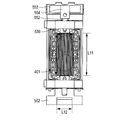
- FIG. 25 shows the state of light incident on the diffraction grating 401 of the actuator 500 of the present embodiment.
- FIG. 26 shows the state of light incident on the diffraction grating 1 of the actuator 100 of the first embodiment.
- a portion indicated by a circle in the drawing indicates light incident on the diffraction gratings 401 and 1.
- the diffraction gratings 401 and 1 are both attached so that the grating grooves of the diffraction gratings 401 and 1 are parallel to the axial direction of the rotation axis.
- the axial direction of the rotation axis that is, the direction parallel to the grating grooves of the diffraction gratings 401 and 1 is referred to as the vertical direction, and the direction orthogonal thereto is referred to as the horizontal direction.
- the longitudinal length L11 of the diffraction grating 1 is substantially equal to the lateral length L12.
- the longitudinal length L11 of the diffraction grating 401 of this embodiment shown in FIG. 25 handles two light sources, the longitudinal length L11 of the diffraction grating 401 is longer than the lateral length L12.
- the length L11 in the vertical direction of the diffraction grating 401 is at least twice as long as the length L12 in the horizontal direction.
- the diffraction grating 401 can enter and emit light parallel to each other from the two light sources.
- the length L11 in the vertical direction of the diffraction grating 401 may be N times or more than the length L12 in the horizontal direction.
- the diffraction grating is configured to be long in the horizontal direction.
- the light sources are arranged in the vertical direction without being arranged in the horizontal direction.
- a rectangular diffraction grating 401 having a long side parallel to the axial direction of the rotation axis and a short side perpendicular to the axial direction of the rotation axis is used, but the diffraction grating is not necessarily rectangular.
- the essential point is not limited to this, as long as it has a shape that allows a plurality of light sources to be irradiated side by side in the axial direction of the rotation axis, that is, the direction parallel to the grating grooves of the diffraction grating 401.
- the lateral length L12 is unnecessarily long, the size of the apparatus is increased. Therefore, it is preferable that the diffraction grating 401 is elongated in the axial direction of the rotation axis, that is, in the direction parallel to the grating grooves of the diffraction grating 401. .
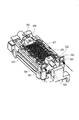
- the plate spring 530 of the actuator 500 is provided with a gel 601 as a buffer member that suppresses vibration of the plate spring 530.
- the gel 601 may be provided so that a gel pod 602 having a concave cross section is formed in the holder 550 and the gel pod 602 is filled.
- the gel 601 is provided in the vicinity of four roots where the leaf springs 530 are attached.
- the position where the gel 601 is disposed is not limited to this, and in short, it may be disposed at a position where ringing of the leaf spring 530 can be reduced.
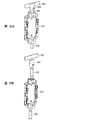
- FIG. 28 shows the mounting structure of the rotating shaft according to the present embodiment.
- FIG. 28A shows a state where the rotary shaft 552 is attached to the holder 550
- FIG. 28B shows a state before the rotary shaft of the holder 550 is attached.
- the holder 550 and the rotation shaft 552 are configured separately, and the rotation shaft 552 is attached to the holder 550. Thereby, the holder 550 can be rotated with high accuracy.
- the holder 550 is made of, for example, polycarbonate resin, and the rotating shaft 552 is made of, for example, metal.
- a reflection plate 553 is attached to one rotating shaft 552 via a cap 554.
- a high level of manufacturing technology is required. If the rotation shaft 52 is displaced as a result of molding as shown in FIG. 29A, one of the rotation shafts 52 comes off from the bearing 21a as shown in FIG. 29B, or the rotation shaft 52 of the rotation shaft 52 as shown in FIG. 29C. One inconvenience arises that one of them rotates while swinging in the bearing 21a. If the holder 550 and the rotating shaft 552 are configured separately as in the present embodiment, and the rotating shaft 552 is attached to the holder 550 with the jig as a reference, the axis shift as shown in FIG. Inconvenience can be prevented.
- the resin is poured from the injection hole 555 and the rotating shaft 552 is inserted into the holder 550.
- the diameter of the hole of the holder 550 for inserting the rotating shaft 552 is set to a size having a margin when the rotating shaft 552 is inserted, and the position of the rotating shaft 552 is adjusted using a jig to the holder 550. If the rotation shaft 552 is fixed, the rotation shaft 552 can be attached to a desired position without any axial deviation.
- FIG. 31 shows a state of electrical connection of the leaf spring 530 to the flexible printed circuit board 590.
- power is supplied from the flexible printed board 590 to the coil 540 through the leaf spring 530. Therefore, it is necessary to electrically connect the flexible printed circuit board 590 and the leaf spring 530.
- a wall portion 591 is formed by projecting a part of the flexible printed circuit board 590 from the mounting surface of the holder 550 on which the plate spring 530 is mounted, and the connection formed on the wall portion 591 is formed.
- One end of the leaf spring 530 is inserted into the use hole, and soldering is performed from the outside of the wall portion 591 as indicated by an arrow in this state, thereby electrically connecting the flexible printed board 590 and the leaf spring 530.
- soldering is performed from the outside of the wall portion 591 as indicated by an arrow in this state, thereby electrically connecting the flexible printed board 590 and the leaf spring 530.
- the current sensitivity of the actuator 500 by increasing the spring constant of the leaf spring 530. That is, if the spring constant of the leaf spring 530 is increased, the angle error of the actuator 500 relative to the error of the VCM driver can be made insensitive (in other words, the current sensitivity can be reduced), and used as a spectroscope, for example. In this case, the required wavelength accuracy can be ensured.
- a cantilever structure using a ball bearing may be adopted instead of the rotating shafts 52 and 552.
- a cantilever structure using a ball bearing may be adopted instead of the rotating shafts 52 and 552.
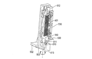
- 32 and 33 are diagrams showing this state.
- a rotation shaft 611 is formed at one end of the holder 550 in the vertical direction, and this rotation shaft 611 is rotatably supported by a ball bearing 610 mounted on a housing 613 provided on the base 503.
- the shaft 612 formed at the other end of the holder 550 functions not as a shaft for supporting the holder 550 but as a shaft for moving the reflecting plate 553.
- the diffraction grating 401 has a shape in which the length in the axial direction of the rotation shaft 552 is longer than the length in the direction orthogonal to the axial direction of the rotation shaft 552.
- a uniaxial rotary actuator 500 suitable for forming light having a wide wavelength range can be realized.
- the optical element attached to the holder 550 is not limited to the diffraction grating 401, and for example, a mirror or the like may be attached.
- the actuator 500 according to the above-described embodiment can be used as an actuator such as a spectroscope actuator or a rotation mechanism for changing the light distribution of an automobile headlight.
- the configuration described in the present embodiment can also be applied to the actuator 100 of the first embodiment. That is, the configuration of Embodiment 1 and the configuration of Embodiment 2 can be used in combination as appropriate.
- the uniaxial rotary actuator of the present invention can be used as an actuator that rotationally drives a diffraction grating of a spectroscope, for example.
Landscapes
- Physics & Mathematics (AREA)
- Spectroscopy & Molecular Physics (AREA)
- General Physics & Mathematics (AREA)
- Optics & Photonics (AREA)
- Mechanical Light Control Or Optical Switches (AREA)
- Spectrometry And Color Measurement (AREA)
Abstract
L'invention concerne un actionneur rotatif à axe unique qui est approprié pour entraîner en rotation un élément optique, tel qu'un réseau de diffraction, dans une direction d'axe unique et qui est approprié pour former une lumière ayant une large bande de longueur d'onde. Un actionneur (500) comprend un support (550) ayant une surface de montage sur laquelle un réseau de diffraction (401) est fixé et un arbre rotatif (552) ; une unité fixe (520) ayant un palier qui maintient l'arbre rotatif (552) du support (550) ; un élément élastique (530) formé d'une section circonférentielle externe fixée sur l'unité fixe (520), d'une section circonférentielle interne fixée sur le support (550), et d'une section bras reliant la section circonférentielle externe et la section circonférentielle interne et ayant une certaine élasticité ; et une unité d'entraînement ayant une bobine (540) disposée sur le support (550) et un aimant (510) disposé sur l'unité fixe (520).
Priority Applications (2)
| Application Number | Priority Date | Filing Date | Title |
|---|---|---|---|
| US16/091,557 US11131846B2 (en) | 2016-04-05 | 2017-03-31 | Single-axis rotary actuator |
| CN201780020901.9A CN109073878A (zh) | 2016-04-05 | 2017-03-31 | 单轴旋转致动器 |
Applications Claiming Priority (2)
| Application Number | Priority Date | Filing Date | Title |
|---|---|---|---|
| JP2016-075893 | 2016-04-05 | ||
| JP2016075893A JP2017187603A (ja) | 2016-04-05 | 2016-04-05 | 1軸回転アクチュエーター |
Publications (1)
| Publication Number | Publication Date |
|---|---|
| WO2017175672A1 true WO2017175672A1 (fr) | 2017-10-12 |
Family
ID=60000484
Family Applications (1)
| Application Number | Title | Priority Date | Filing Date |
|---|---|---|---|
| PCT/JP2017/013530 Ceased WO2017175672A1 (fr) | 2016-04-05 | 2017-03-31 | Actionneur rotatif à axe unique |
Country Status (5)
| Country | Link |
|---|---|
| US (1) | US11131846B2 (fr) |
| JP (1) | JP2017187603A (fr) |
| CN (1) | CN109073878A (fr) |
| TW (1) | TW201736904A (fr) |
| WO (1) | WO2017175672A1 (fr) |
Cited By (1)
| Publication number | Priority date | Publication date | Assignee | Title |
|---|---|---|---|---|
| EP3841427A1 (fr) * | 2018-08-20 | 2021-06-30 | Optotune AG | Dispositif optique permettant d'améliorer la résolution d'une image ou de réduire le bruit speckle |
Families Citing this family (5)
| Publication number | Priority date | Publication date | Assignee | Title |
|---|---|---|---|---|
| JP7137321B2 (ja) * | 2018-02-28 | 2022-09-14 | 浜松ホトニクス株式会社 | 可動回折格子、外部共振器型レーザモジュール、可動回折格子の製造方法 |
| US20210139314A1 (en) * | 2019-11-07 | 2021-05-13 | Innovative Interface Laboratory Corp. | Linear actuator |
| CN111207832B (zh) * | 2020-03-09 | 2022-08-12 | 厦门大学嘉庚学院 | 一种基于定频率光栅和单点传感器的光谱探测系统及方法 |
| JPWO2021260949A1 (fr) * | 2020-06-26 | 2021-12-30 | ||
| CN111896107B (zh) * | 2020-07-31 | 2025-02-25 | 安徽创谱仪器科技有限公司 | 光栅单色器 |
Citations (5)
| Publication number | Priority date | Publication date | Assignee | Title |
|---|---|---|---|---|
| JPS5733434U (fr) * | 1980-08-04 | 1982-02-22 | ||
| JP2002156591A (ja) * | 2000-11-16 | 2002-05-31 | Olympus Optical Co Ltd | ガルバノミラー |
| US20080304017A1 (en) * | 2007-06-05 | 2008-12-11 | Young Optics Inc. | Imaging displacement module |
| JP2009085947A (ja) * | 2007-09-14 | 2009-04-23 | Sanyo Electric Co Ltd | ビーム照射装置 |
| JP2014157015A (ja) * | 2011-05-27 | 2014-08-28 | Sanyo Electric Co Ltd | ミラーアクチュエータおよびビーム照射装置 |
Family Cites Families (16)
| Publication number | Priority date | Publication date | Assignee | Title |
|---|---|---|---|---|
| US5220550A (en) | 1990-08-10 | 1993-06-15 | Alps Electric Co., Ltd. | Optical beam system for optical disk drives |
| JP2003317304A (ja) * | 2002-04-25 | 2003-11-07 | Mitsumi Electric Co Ltd | 光ピックアップ |
| US20080068734A1 (en) * | 2004-07-09 | 2008-03-20 | Murakami Corporation | Mirror Surface Control Actuator and Process for Manufacturing Same |
| KR100636347B1 (ko) * | 2004-08-18 | 2006-10-19 | 엘지전자 주식회사 | 스캐닝 디스플레이 시스템 |
| JP2006189672A (ja) * | 2005-01-07 | 2006-07-20 | Nippon Sheet Glass Co Ltd | 光学モジュール |
| WO2007029643A1 (fr) * | 2005-09-07 | 2007-03-15 | Alps Electric Co., Ltd. | Actionneur et dispositif holographique l’utilisant |
| JP4489678B2 (ja) * | 2005-09-30 | 2010-06-23 | 富士通株式会社 | 波長選択光スイッチおよび分光機能を備えた光デバイス |
| CN101083423B (zh) * | 2006-05-29 | 2010-07-14 | 深圳市大族精密机电有限公司 | 振镜电机 |
| JP5232396B2 (ja) * | 2007-03-13 | 2013-07-10 | 三洋電機株式会社 | ビーム照射装置 |
| US8102514B2 (en) * | 2007-09-14 | 2012-01-24 | Sanyo Electric Co., Ltd. | Beam irradiation apparatus |
| KR100956890B1 (ko) | 2008-06-17 | 2010-05-11 | 삼성전기주식회사 | 스캐너 |
| US8593712B2 (en) | 2009-07-17 | 2013-11-26 | Nec Corporation | Small size fast steering mirror having small size and excellent vibration characteristics |
| KR20110066860A (ko) * | 2009-12-11 | 2011-06-17 | 산요 덴키 가부시키가이샤 | 리니어 액추에이터 |
| CN102869963A (zh) * | 2010-05-05 | 2013-01-09 | 台湾超微光学股份有限公司 | 微型光谱仪的光学机构 |
| JP2012145905A (ja) * | 2010-12-24 | 2012-08-02 | Sanyo Electric Co Ltd | ミラーアクチュエータおよびビーム照射装置 |
| CN104024918A (zh) * | 2011-11-30 | 2014-09-03 | 三洋电机株式会社 | 反射镜致动器、光束照射装置及激光雷达 |
-
2016
- 2016-04-05 JP JP2016075893A patent/JP2017187603A/ja active Pending
-
2017
- 2017-03-31 TW TW106111009A patent/TW201736904A/zh unknown
- 2017-03-31 WO PCT/JP2017/013530 patent/WO2017175672A1/fr not_active Ceased
- 2017-03-31 CN CN201780020901.9A patent/CN109073878A/zh active Pending
- 2017-03-31 US US16/091,557 patent/US11131846B2/en not_active Expired - Fee Related
Patent Citations (5)
| Publication number | Priority date | Publication date | Assignee | Title |
|---|---|---|---|---|
| JPS5733434U (fr) * | 1980-08-04 | 1982-02-22 | ||
| JP2002156591A (ja) * | 2000-11-16 | 2002-05-31 | Olympus Optical Co Ltd | ガルバノミラー |
| US20080304017A1 (en) * | 2007-06-05 | 2008-12-11 | Young Optics Inc. | Imaging displacement module |
| JP2009085947A (ja) * | 2007-09-14 | 2009-04-23 | Sanyo Electric Co Ltd | ビーム照射装置 |
| JP2014157015A (ja) * | 2011-05-27 | 2014-08-28 | Sanyo Electric Co Ltd | ミラーアクチュエータおよびビーム照射装置 |
Cited By (1)
| Publication number | Priority date | Publication date | Assignee | Title |
|---|---|---|---|---|
| EP3841427A1 (fr) * | 2018-08-20 | 2021-06-30 | Optotune AG | Dispositif optique permettant d'améliorer la résolution d'une image ou de réduire le bruit speckle |
Also Published As
| Publication number | Publication date |
|---|---|
| US11131846B2 (en) | 2021-09-28 |
| TW201736904A (zh) | 2017-10-16 |
| JP2017187603A (ja) | 2017-10-12 |
| US20190107712A1 (en) | 2019-04-11 |
| CN109073878A (zh) | 2018-12-21 |
Similar Documents
| Publication | Publication Date | Title |
|---|---|---|
| WO2017175672A1 (fr) | Actionneur rotatif à axe unique | |
| CN109690887B (zh) | 光输出模块和lidar | |
| US5808727A (en) | Vehicle optical radar apparatus | |
| CN112014827A (zh) | 物体检测装置 | |
| CN111381328B (zh) | 驱动机构 | |
| CN109991619A (zh) | 物体检测装置、物体检测方法及物体检测装置的设计方法 | |
| WO2012077772A1 (fr) | Unité de correction de flou d'image, dispositif de correction de flou d'image et appareil optique | |
| CN107339654B (zh) | 旋转式灯模块 | |
| JP2006071545A (ja) | 回転レーザ装置 | |
| CN119781131A (zh) | 光学元件驱动机构 | |
| JP2007316157A (ja) | 投光光学系及びそれを備えた投光装置 | |
| JP2006303955A (ja) | 撮像装置及び電子機器 | |
| JP5900682B1 (ja) | 1軸回転アクチュエーター | |
| US9684224B2 (en) | Light adjusting apparatus and method for measuring distance between substrates of light adjusting apparatus | |
| JP6561878B2 (ja) | 1軸回転アクチュエーター | |
| JP2020126243A (ja) | 1軸回転アクチュエーター | |
| WO2017183629A1 (fr) | Spectroscope et dispositif de mesure | |
| CN120352853A (zh) | 光学系统和旋转式激光雷达 | |
| JP2005164649A (ja) | 光学装置及び光電センサ | |
| CN120522671A (zh) | 电机转镜组件和旋转式激光雷达 | |
| JP4849505B2 (ja) | 位置検出装置、該位置検出装置を有する光学装置 | |
| WO2024128291A1 (fr) | Élément de culasse et dispositif de balayage | |
| WO2024128290A1 (fr) | Dispositif de détection d'inclinaison et procédé de détection d'inclinaison | |
| WO2011118397A1 (fr) | Module d'émission/de lumière/réception de lumière térahertz et procédé de commande de polarisation de lumière térahertz | |
| JP4989988B2 (ja) | 光学系駆動装置およびレーザスキャン装置 |
Legal Events
| Date | Code | Title | Description |
|---|---|---|---|
| NENP | Non-entry into the national phase |
Ref country code: DE |
|
| 121 | Ep: the epo has been informed by wipo that ep was designated in this application |
Ref document number: 17779051 Country of ref document: EP Kind code of ref document: A1 |
|
| 122 | Ep: pct application non-entry in european phase |
Ref document number: 17779051 Country of ref document: EP Kind code of ref document: A1 |