WO2017175765A1 - 衣類製造装置及び衣類製造方法 - Google Patents
衣類製造装置及び衣類製造方法 Download PDFInfo
- Publication number
- WO2017175765A1 WO2017175765A1 PCT/JP2017/014110 JP2017014110W WO2017175765A1 WO 2017175765 A1 WO2017175765 A1 WO 2017175765A1 JP 2017014110 W JP2017014110 W JP 2017014110W WO 2017175765 A1 WO2017175765 A1 WO 2017175765A1
- Authority
- WO
- WIPO (PCT)
- Prior art keywords
- garment
- disposable pants
- sheet
- manufacturing apparatus
- fiber sheet
- Prior art date
- Legal status (The legal status is an assumption and is not a legal conclusion. Google has not performed a legal analysis and makes no representation as to the accuracy of the status listed.)
- Ceased
Links
Images





Classifications
-
- A—HUMAN NECESSITIES
- A41—WEARING APPAREL
- A41H—APPLIANCES OR METHODS FOR MAKING CLOTHES, e.g. FOR DRESS-MAKING OR FOR TAILORING, NOT OTHERWISE PROVIDED FOR
- A41H43/00—Other methods, machines or appliances
- A41H43/02—Handling garment parts or blanks, e.g. feeding, piling, separating or reversing
-
- A—HUMAN NECESSITIES
- A61—MEDICAL OR VETERINARY SCIENCE; HYGIENE
- A61F—FILTERS IMPLANTABLE INTO BLOOD VESSELS; PROSTHESES; DEVICES PROVIDING PATENCY TO, OR PREVENTING COLLAPSING OF, TUBULAR STRUCTURES OF THE BODY, e.g. STENTS; ORTHOPAEDIC, NURSING OR CONTRACEPTIVE DEVICES; FOMENTATION; TREATMENT OR PROTECTION OF EYES OR EARS; BANDAGES, DRESSINGS OR ABSORBENT PADS; FIRST-AID KITS
- A61F13/00—Bandages or dressings; Absorbent pads
- A61F13/15—Absorbent pads, e.g. sanitary towels, swabs or tampons for external or internal application to the body; Supporting or fastening means therefor; Tampon applicators
- A61F13/15577—Apparatus or processes for manufacturing
- A61F13/15804—Plant, e.g. involving several steps
-
- A—HUMAN NECESSITIES
- A41—WEARING APPAREL
- A41H—APPLIANCES OR METHODS FOR MAKING CLOTHES, e.g. FOR DRESS-MAKING OR FOR TAILORING, NOT OTHERWISE PROVIDED FOR
- A41H43/00—Other methods, machines or appliances
- A41H43/02—Handling garment parts or blanks, e.g. feeding, piling, separating or reversing
- A41H43/025—Folding, unfolding or turning over
- A41H43/0264—Turning over
-
- D—TEXTILES; PAPER
- D06—TREATMENT OF TEXTILES OR THE LIKE; LAUNDERING; FLEXIBLE MATERIALS NOT OTHERWISE PROVIDED FOR
- D06G—MECHANICAL OR PRESSURE CLEANING OF CARPETS, RUGS, SACKS, HIDES, OR OTHER SKIN OR TEXTILE ARTICLES OR FABRICS; TURNING INSIDE-OUT FLEXIBLE TUBULAR OR OTHER HOLLOW ARTICLES
- D06G3/00—Turning inside-out flexible tubular or other hollow articles
- D06G3/02—Turning inside-out flexible tubular or other hollow articles by mechanical means
Definitions
- the present invention relates to a garment manufacturing apparatus and a garment manufacturing method.
- Patent Document 1 requires time and once it is necessary to return after having passed through the clothes (sleeves) once the barbed member and the arm member, the production efficiency is poor. Further, the technique described in Patent Document 1 or the like is difficult to apply to a garment having three openings (for example, a garment for the lower body having a waist opening and two leg openings).
- An object of the present invention is to provide a garment manufacturing apparatus and a garment manufacturing method with high production efficiency.
- a tubular body having openings at both ends, the tubular body passes through the waist opening of the garment for the lower body, and the crotch of the garment for the lower body is the tubular body
- the lower body garment positioned so as to cover one opening is passed from the crotch to the inside of the tubular body to invert the front and back of the lower body garment.
- the waist opening of the garment for the lower body is inserted into the tubular body having openings at both ends, and the crotch portion of the garment for the lower body covers one opening of the tubular body.
- the clothes manufacturing apparatus and the clothes manufacturing method of the present invention have an effect that production efficiency can be improved.
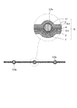
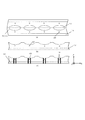
- FIG. 4 is a cross-sectional view taken along the line AA of FIG. 3;
- FIG. 4 is a cross-sectional view taken along the line BB of FIG.
- FIG. 8A and FIG. 8B are diagrams showing the first folding process.
- FIGS. 9 (a) to 9 (c) are diagrams showing a process from the drilling process to the bonding process. It is a figure which shows one disposable pants obtained by cutting
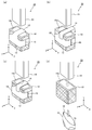
- FIGS. 11 (a) to 11 (d) are diagrams showing a reverse apparatus for disposable pants.
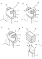
- FIGS. 12 (a) to 12 (d) are diagrams showing a modification (part 1) of the everting device for disposable pants.
- FIGS. 13 (a) to 13 (d) are diagrams showing a modification (part 2) of the everting device for disposable pants. It is a figure which shows a mode that an absorber was attached to a disposable pants and it wore. It is a schematic diagram showing a modification of a manufacturing device of disposable pants. It is the figure which looked at a part of manufacturing apparatus of FIG. 15 from + Z direction.
- FIGS. 17 (a) to 17 (c) are diagrams showing the processing from the drilling process to the bonding process of the manufacturing apparatus of FIG. Fig.18 (a) and FIG.18 (b) are figures which show the disposable pants after the cutting process in the modification of the manufacturing apparatus of disposable pants.
- the fabric 1 shown in FIG. 1 and the like is used as the outer covering sheet 11 of the disposable pants 10 which is a disposable lower-body garment.
- Dough 1 may be applied to a disposable diaper, and can also be used as a surface material of an absorbent 14 (absorbent pad) of a disposable diaper or disposable pants 10.
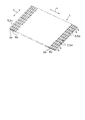
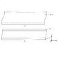
- FIG. 1 is a view showing the surface state of the dough 1 of the present embodiment
- FIG. 2 is a view showing a buttock of the dough 1
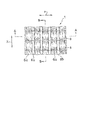
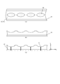
- FIG. 3 is an enlarged view of the dough 1.
- the dough 1 will be described in detail with reference to FIGS. 1 to 3.
- the fabric 1 has an elongated configuration continuous in the x direction, which is the longitudinal direction (first direction).
- the elastic member 5 is provided in the inside of the fabric 1 along the x direction, as is apparent from FIGS. 1 and 2, and a plurality of elastic members 5 are provided at predetermined intervals in the y direction which is the short direction (second direction) of the fabric 1 It is done.
- the elastic member 5 expands and contracts along the x direction. As shown in FIG. 2, an uneven surface, that is, a ridge portion is formed on the cloth 1 by a large number of elastic members 5.
- a linear elastic body 5a having stretchability is used, and synthetic rubber or natural rubber based on urethane, silicone, butadiene, or styrene / butadiene can be used.
- a stretchable film may be used.
- a urethane film, a silicone film, an elastomer film or the like can be used.
- the fabric 1 is a first fiber sheet 2 which is a breathable sheet, a second fiber sheet 3 which has a liquid diffusivity, a first fiber sheet 2 and a second fiber sheet. And a third fiber sheet 4 having liquid diffusibility interposed between three, and a laminated sheet 15 formed by laminating the first fiber sheet 2, the second fiber sheet 3 and the third fiber sheet 4 .
- the first fiber sheet 2 and the second fiber sheet 3 are formed of a breathable fiber layer, and the third fiber sheet 4 is formed of a liquid diffusion fiber layer.
- the lamination sheet 15 is comprised from three layers.
- the laminated sheet 15 may have a two-layer structure by omitting the third fiber sheet 4 or may have a two-layer structure by omitting the second fiber sheet 3.
- the first fiber sheet 2 is on the side (skin surface side) in contact with the user's skin.
- the fiber sheet 3 is on the outer side (non-skin surface side).
- the x direction in FIG. 1 of the dough 1 matches the X direction shown in FIG. 8, FIG. 9, FIG. 16, FIG. 17, etc., and the y direction in FIG.
- the fabric 1 is applied to the exterior sheet 11 so as to coincide with the Y direction shown.
- the first fiber sheet 2 is a non-woven fabric, and a two-layer or three-layer spunbond non-woven fabric can be used.
- a hydrophilic non-woven fabric as the first fiber sheet 2.
- a hydrophilization treatment such as adding a hydrophilizing agent to the dough 1 may be performed.
- the weight per unit area of the first fiber sheet 2 is preferably 10 to 50 g / m 2 as an example, and more preferably 10 to 20 g / m 2 from the viewpoint of manufacturing cost, but is not limited thereto.
- the second fiber sheet 3 is a non-woven fabric, and a two-layer or three-layer spunbond non-woven fabric can be used.
- a water-repellent sheet As the water repellent non-woven fabric, a spunbond non-woven fabric of 3 layers can be used, and it is preferable to carry out a water repellent treatment coated with a water repellent agent of fluorine type, silicone type, paraffin metal type, and alkylchromic croid type.
- the basis weight of the nonwoven fabric water-repellent preferably 10 ⁇ 50g / m 2 as an example, but more preferably 10 ⁇ 20g / m 2 in terms of production costs, but is not limited thereto.
- the 3rd fiber sheet 4 can use the material which uses pulp as the main raw material, ie, the material containing the component of a cellulose system, for example, can use pulp fiber sheets, such as tissue paper, crepe paper, air laid nonwoven fabric, etc. .
- pulp fiber sheets such as tissue paper, crepe paper, air laid nonwoven fabric, etc.
- wood pulp, synthetic pulp, waste paper pulp and the like can be used.
- not only natural fibers such as pulp but also regenerated fibers such as rayon can be used.
- the weight per unit area of the third fiber sheet 4 is preferably 10 to 50 g / m 2 as an example.
- the print layer 4a may be formed in advance on the third fiber sheet 4 (pulp fiber sheet), and various prints may be performed.
- the first fiber sheet 2 and the third fiber sheet 4 are joined by an adhesive 17 applied to the circumferential surface of the elastic member 5. Therefore, in the portion where the elastic member 5 does not exist, the non-adhered portion 8 where the adhesive 17 does not exist is formed between the first fiber sheet 2 and the third fiber sheet 4, and the space 9 is formed by the non-adhered portion 8. It is formed. In the present embodiment, since the space 9 is formed by the non-adhesive portion 8, it is possible to improve each of the functions of water evaporation, heat dissipation and moisture permeability in the dough 1.
- the adhesive 17 partially (intermittently) on at least one of the first fiber sheet 2 and the third fiber sheet 4 May be applied to bond the first fiber sheet 2 and the third fiber sheet 4. Also in this case, since the first fiber sheet 2 and the third fiber sheet 4 are partially (intermittently) joined, the space 9 is formed between the first fiber sheet 2 and the third fiber sheet 4 It can be formed.
- the adhesive 17 various adhesives, such as a pressure sensitive adhesive and a curable adhesive, can be used, and the hot-melt adhesive is employ
- the bonding of the first fiber sheet 2 and the second fiber sheet 3 is not limited to bonding, and various bonding methods such as ultrasonic bonding and heat sealing may be applied or used in combination.
- the ridge portion is formed on the entire cloth 1 by continuously forming the convex portion 6a and the concave portion 6b between the adjacent linear elastic bodies 5a. Be done.
- the intervals at which the linear elastic bodies 5a are provided in the y direction may be substantially equal intervals.
- the linear elastic bodies 5a may be densely arranged by shortening the intervals at the periphery of the fabric 1. .
- the space may be shortened from the center to the periphery of the dough 1.
- the elastic force of the linear elastic body 5a at the peripheral portion of the fabric 1 and the elastic force of the linear elastic body 5a at the central portion are made different, and the linear portion of the peripheral portion You may make it strengthen the elastic force of the elastic body 5a.
- the linear elastic body is made so that the elastic force of the body attachment portion 12 (see FIG. 14) is larger than the elastic force of the other portions. It is sufficient to arrange 5a.
- the linear elastic body 5 a is provided between the first fiber sheet 2 and the third fiber sheet 4 as described above.
- a large number of uneven rows 6 are formed in the y direction in FIGS. 1 and 2.
- the number of linear elastic bodies 5a per unit area can be set arbitrarily, but if the number of linear elastic bodies 5a is increased to reduce the distance between the linear elastic bodies 5a, the convex portions in a row of uneven rows 6 6a and the recessed part 6b can be formed in a uniform shape, and the shape can be maintained. As a result, there is no shape deformation of the buttocks, and the flexibility, moisture transpiration, heat dissipation and moisture permeability of the dough 1 can be increased.
- the pitch interval between the convex portions 6a in one concavo-convex row 6 is preferably 2.00 mm to 7.00 mm.
- the pitch distance between the convex portions 6a is more preferably 3.00 mm to 6.25 mm.
- the elastic force of the linear elastic body 5a can be appropriately suppressed by widening the pitch interval between the convex portions 6a, and the manufacturing cost can be reduced.
- the dough 1 (also referred to as the laminated sheet 15) has a long dimension
- cutting is performed to make the dimension in the longitudinal direction (the x direction in FIG. 1 and FIG. 2) of the laminated sheet 15 be a predetermined length.
- the first fiber sheet 2, the second fiber sheet 3, the third fiber sheet 4 and the elastic member 5 are cut.
- the elastic member 5 in the pulled state is released from the tensile force and is contracted by the restoring force.
- the dough 1 (laminated sheet 15) receives a force in the direction in which the length is shortened due to the contraction stress, so that a plurality of uneven rows 6 are formed on the dough 1 (laminated sheet 15), thereby forming a ridge Be done.
- the dough 1 having a large number of buttocks is manufactured.
- the cloth 1 has a large surface area per unit volume because the size as the disposable pants 10 is determined in the contracted size by the restoring force of the elastic member 5.
- the body fluid urine, sweat, blood, etc.
- SAP super absorbent polymer
- the absorber 14 can perform various deformation
- a surface material (top sheet) made of the dough 1 may be provided on the absorbent body 14.
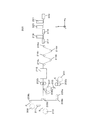
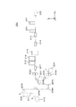
- FIG. 6 is a schematic view showing the manufacturing apparatus 200 of the disposable pants 10
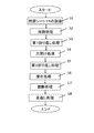
- FIG. 7 is a flowchart showing a method of manufacturing the disposable pants 10.
- the layout of the manufacturing apparatus 200 of FIG. 6 is merely an example, and the arrangement of various apparatuses can be changed as appropriate depending on the space requirements of the factory.
- Step S1 manufacture of laminated sheet 15
- the third fiber sheet 4 wound around the sheet roll 201 is conveyed in the -X direction, and is embossed by the pair of embossing rolls 202a. Thereby, the 3rd fiber sheet 4 is softened.
- symbol alphabet
- symbol alphabet
- each embossing roll 202 you may use the same embossing roll, and you may use the embossing roll from which an embossing pattern, a magnitude
- the third fiber sheet 4 is printed in advance on the third fiber sheet 4 wound around the sheet roll 201, and the above-described embossing is applied to the third fiber sheet 4 on which the pattern is printed. Be done.
- the cloth 1 which has the 3rd fiber sheet 4 for the surface material of the absorber 14 mentioned above, it can print on the printing layer 4a of the 3rd fiber sheet 4.
- FIG. For example, characters such as “front side”, “back side”, arrows, figures, pictograms may be printed and used as a mark when attaching the absorber 14 to the disposable pants 10, when using the absorber 14 May be printed, colored, or a pattern may be printed. It is desirable that the printing on the third fiber sheet 4 be performed on the third fiber sheet 4 before the fabric 1 is laminated.
- the adhesive 7 is applied to the third fiber sheet 4 having passed through the embossing roll 202 a by the first adhesive applying device 203.
- a hot melt adhesive is used as the adhesive 7, but it is not limited to this.
- the adhesive 7 is heated to a predetermined temperature (for example, 60 ° C. to 150 ° C.) by the first adhesive application device 203.
- the second fiber sheet 3 wound around the sheet roll 207 is conveyed in the ⁇ Z direction by the conveyance roll 208a, and is joined by the pressing roll 209a to the third fiber sheet 4 to which the adhesive 7 is applied. And the 2nd fiber sheet 3 and the 3rd fiber sheet 4 which were joined are conveyed by + Z direction by the conveyance roll 208b.
- a code alphabet
- these transport rolls 208 may be the same transport roll, or The transport rolls may have different rotation speeds.
- a code (alphabet) is added and described, but these pressing rolls 209 may be the same pressing roll 209. Or different pressure rolls.
- the number of pressing rolls 209, the size of the pressing rolls 209, the pressing force, and the like can be set as appropriate.
- the adhesive 17 is applied to the elastic member 5 wound around the elastic roll 210 by the second adhesive application device 211.
- a hot melt adhesive is used as the adhesive 17.
- the adhesive 17 and the adhesive 7 may be the same hot melt adhesive or may be different (for example, different in viscosity).
- the adhesives 7 and 17 are heated to a predetermined temperature (for example, 60 ° C. to 150 ° C.) by the second adhesive application device 211.
- a predetermined temperature for example, 60 ° C. to 150 ° C.
- the first fiber sheet 2 wound around the sheet roll 206 is conveyed by the conveyance roll 208 c in the ⁇ Z direction.
- the 2nd fiber sheet 3 and the 3rd fiber sheet 4 which were joined as mentioned above are conveyed by + Z direction by conveyance roll 208b.
- the first fiber sheet 2 and the joined second fiber sheet 3 and third fiber sheet 4 are pressed and joined by the pair of pressing rolls 209 b through the elastic member 5 to which the adhesive 17 is applied. .
- the lamination sheet 15 is manufactured.
- the lamination sheet 15 is laminated
- the laminated sheet 15 is embossed by the pair of embossing rolls 202b. Thereby, the lamination sheet 15 is softened.
- the pair of emboss rolls 202b may be provided on the rear side (+ X side) of the heating device 215, or may be provided on the front and rear ( ⁇ X side and + X side) of the heating device 215. Also, the embossing roll 202b may be omitted.
- Step S2 heat treatment
- the elastic force is applied to the laminated sheet 15 by the elastic member 5 disposed inside the laminated sheet 15.
- the surface area per unit length in the X direction can be increased to about 1.5 times to 5 times. For example, if the required dimension in the X direction is 800 mm, dough 1 (in the stretched state) of 1200 mm to 4000 mm will be used.
- the contraction rate (catalog value or theoretical value), which is the rate of contraction from a state stretched to a predetermined length to a state contracted most by the restoring force of the elastic member 5, is 1/3
- X of the fabric 1 As a dimension of the direction, 2400 mm multiplied by the reciprocal of the contraction rate of the elastic member 5 is required.
- the first fiber sheet 2, the second fiber sheet 3, and the third fiber sheet 4 are actually joined via the elastic member 5 and then cut or the conveyance speed of the conveyance roll is reduced to release the stretched state. Even then, the contraction rate may be 1 ⁇ 2.
- the shrinkage of the elastic member 5 due to the curing of the adhesive 17 and the rigidity of the third fiber sheet 4 are affected.
- the application conditions (application temperature, application amount, viscosity, etc.) of the adhesive 17 may also be affected.
- the application conditions (application temperature, application amount, viscosity, etc.) of the adhesive 7 may also be affected.
- the elastic member 5 when the elastic member 5 is a thermosetting type, the elastic member 5 is hardened and the contraction rate of the elastic member 5 is made to approach theoretical value.
- the laminated sheet 15 is conveyed in a stretched state.
- the heating device 215 is a non-contact heating device that supplies air at, for example, 30 ° C. to 80 ° C.
- the heating roll 216 is heated to, for example, 30 ° C. to 80 ° C., and the heating rolls 216 a and 216 c contact the second fiber sheet 3 of the laminated sheet 15 to heat the laminated sheet 15, and the heating rolls 216 b and 216 d are laminated.
- the laminated sheet 15 is heated in contact with the first fiber sheet 2 of the sheet 15.
- four heating rolls 216 are used in the present embodiment, the number is not limited and can be set as appropriate.
- non-contact heating by the heating device 215 and contact heating by the heating roll 216 are performed as the heat treatment, but either one may be omitted.
- Step S3 first aliasing process
- the heat-treated laminated sheet 15 is conveyed in the + X direction by the conveying roll 208d, and both ends in the Y direction are each made by the first folding device 217 to form the trunk attachment portion 12 (see FIG. 14) of the disposable pants 10. It is folded back by a predetermined length.
- FIG. 8 is a diagram showing the first folding process.
- the laminated sheet 15 to be the exterior sheet 11 is valley-folded at the dotted line on the + Y side shown in FIG. 8A and the dotted line on the ⁇ Y side to form the shape shown in FIG. 8B.
- the bent portion is the body mounting portion 12 of the disposable pants 10.
- the first folding device 217 is a known device having a folded plate that folds the laminated sheet 15 and a pressing unit that presses the folded laminated sheet 15. Further, the bent portion is joined by various bonding methods such as hot sealing, hot melt adhesive, ultrasonic bonding and the like.
- the first folding device 217 and a bonding device may be provided between the pair of pressure rolls 209 b and the heating device 215. In this case, it may be provided in the front stage of embossing roll 202b, and may be provided in the back stage of embossing roll 202b.
- Step S4 drilling process
- the laminated sheet 15 subjected to the first folding process by the first folding device 217 is conveyed in the + X direction, and is punched by the punching device 218 to form the legs 13 (see FIG. 14) of the disposable pants 10.
- a hole is made by the device 218.
- FIGS. 9 (a) to 9 (c) are diagrams showing a process from the drilling process to the bonding process.
- FIG. 9 (a) shows a laminated sheet 15 which has been perforated. Holes for legs (legs 13) are formed in the laminated sheet 15, and a crotch portion is formed between two adjacent holes (legs 13). Note that the hole drilling process may be performed prior to the first folding process.
- the first fiber sheet 2 is the first fiber sheet with the front side on the paper surface being the skin surface side, and the elastic member 5, the third fiber sheet 4 and the second fiber sheet 3 are in this order It is stacked.
- Step S5 second aliasing process
- the X direction is the longitudinal direction
- the Y direction is the lateral direction.
- the second folding device 219 folds the laminated sheet 15 along the dotted line in the center of FIG.
- the second folding device 219 is an arm member for lifting the dotted line at the center of the laminated sheet 15 so as to mountain-fold it, and a drive unit for driving the arm member so that the mountain-folded laminated sheet 15 is set in a conveying device (not shown)
- FIG. 9 (b) shows a laminated sheet 15 folded back in the lateral direction along the central dotted line in FIG. 9 (a).
- the laminated sheet 15 is in the state of being mountain-folded in the state of FIG.
- the front and back of the laminated sheet 15 is inverted by an inverting mechanism (not shown), and the central portion of the inverted laminated sheet is It may be valley-folded.
- Step S6 bonding process
- the laminated sheet 15 that is mountain-folded in the short direction is joined along the Y direction by the joining device 220 to form the disposable pants 10.
- the bonding device 220 is an ultrasonic bonding device.
- the present invention is not limited to this, and the bonding device 220 may be a device that performs bonding by various bonding methods such as hot sealing and hot melt adhesive.
- FIG. 9C shows the laminated sheet 15 joined by the joining device 220, and a plurality of joined portions 16 (side seals) are formed on the laminated sheet 15 along the Y direction.
- the disposable pants 10 are in a state of being turned over (the first fiber sheet 2 on the skin surface side is exposed outward), and the joint portion is 16 are formed on the non-skin surface side.
- Step S7 cutting process
- the laminated sheet 15 in which the bonding portion 16 is formed is cut by a cutting device 221 provided with a cutter. That is, the cutting device 221 cuts the bonding portion 16 along the Y direction.
- the cutting device 221 cuts the bonding portion 16 along the Y direction.
- one disposable pants 10 is manufactured.
- the state of FIG. 10 is a state in which the disposable pants 10 were turned over (a state in which the first fiber sheet 2 on the skin surface side was exposed outward), the skin surface was in a state of wearing the disposable pants 10 It is necessary to carry out a treatment (reversed treatment) with the second fiber sheet 3 on the side opposite to the side as the surface.
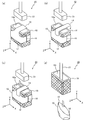
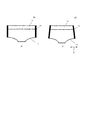
- FIGS. 11 (a) to 11 (d) are views showing the everting device 20 of the disposable pants 10.
- FIG. The reversing device 20 has a cylindrical body 18 and a pushing device 31.
- the cylindrical body 18 has a substantially rectangular parallelepiped shape, and a through hole 18a penetrating from the + Y side surface to the -Y side surface is formed. That is, the cylindrical body 18 has openings on the + Y side surface and the ⁇ Y side surface.
- the cylindrical body 18 does not necessarily have to have a substantially rectangular parallelepiped shape, and may have a cylindrical shape or an elliptical cylindrical shape, and these may have a tapered shape.
- the cylindrical body 18 should just be a cylindrical body as a whole, even if one part of the side wall is opening or it cuts off.
- the outer surface of the cylindrical body 18 (in particular, the surface other than the + Y side surface and the -Y side surface) is roughened to impart resistance to the movement of the disposable pants 10 by being subjected to a matte treatment or the like.
- the inner surface of the through hole 18 a is a smooth surface so as not to resist the movement of the disposable pants 10.
- the pushing device 31 reciprocates in the Y direction by a driving device (not shown). By the movement in the Y direction, the push-in device 31 enters into the through hole 18 a of the cylindrical body 18 or is exposed above the through hole 18 a.
- the cylindrical body 18 is penetrated from the + Y side of the trunk
- the length of the outer periphery of the cylindrical body 18 is the inner periphery of the body mounting portion 12 when the body mounting portion 12 is expanded against the elastic force of the body mounting portion 12 (the inner periphery of the waist opening) Match the length). Therefore, in the state shown in FIG. 11A, the disposable pants 10 are held by the cylindrical body 18 with an appropriate holding force by the elastic force of the body attachment portion 12. Further, in the state of FIG. 11A, the crotch portion of the disposable pants 10 covers a part of the through hole 18a (the opening of the + Y side surface) of the cylindrical body 18 from the + Y side.
- the absorber 14 is attached to the crotch portion of the disposable pants 10 by a device (not shown), a hand or the like as shown in FIG.
- the pushing device 31 moves in the -Y direction toward the crotch of the disposable pants 10 as shown in FIG. It passes through the through hole 18 a of the body 18.
- the disposable pants 10 are mechanically pushed by the pushing device 31, pass through the inside of the cylindrical body 18 (in the through hole 18a), and come out of the through hole 18a as shown in FIG. 11 (d). .
- the disposable pants 10 are turned upside down, that is, turned upside down.
- the bonding portion 16 is located inside (skin side).
- the joint portion 16 is positioned on the skin surface side, the joint portion 16 can not be viewed from the outside.
- the fashion of disposable pants 10 can be improved. In particular, it is possible to reduce the resistance of the user who feels resistance to wearing the paper diaper due to light incontinence and the like.
- the disposable pants 10 are turned over by the simple method of holding the disposable pants 10 on the tubular body 18 and pushing the pushing device 31 into the through holes 18 a of the tubular body 18 and removing the disposable pants 10 from the tubular body 18. It is possible (to separate). Thereby, since the reverse process can be performed efficiently, the productivity of the disposable pants 10 can be improved. Further, in the present embodiment, since the outer surface of the cylindrical body 18 is roughened, appropriate resistance is given when the disposable pants 10 move along the outer surface of the cylindrical body 18. Thus, the disposable pants 10 can be easily turned over, so that the disposable pants 10 can be reliably turned over.
- FIGS. 11 (a) to 11 (d) although the case where the pushing device 31 is used to push the disposable pants 10 into the through holes 18a has been described, the present invention is not limited to this.
- the disposable pants 10 may be pushed into the through holes 18a using a fluid.
- FIGS. 12 (a) to 12 (d) are diagrams showing an example (reverse device 30) using a fluid.
- the reversing device 30 includes a fluid supply device 19 in place of the pushing device 31.
- the fluid supply device 19 supplies a compressed fluid toward the crotch portion of the disposable pants 10, and as one example, supplies a compressed gas.
- various gases can be used as the compressed gas, for example, air having a pressure of 0.2 to 1 MPa can be used.
- the fluid supply device 19 supplies compressed air toward the crotch portion of the disposable pants 10 (see the broken arrow in FIG. 12).
- a force in the -Y direction is applied to the crotch portion of the disposable pants 10
- the disposable pants 10 pass through the through holes 18a of the cylindrical body 18 and, as shown in FIG. Come out of the through hole 18a of In this case, the disposable pants 10 are turned over.
- the junction part 16 is located inside (skin side).
- the fluid supply device 19 may move in the ⁇ Y direction while supplying the compressed gas. This makes it possible to efficiently apply the force in the -Y direction to the crotch portion of the disposable pants 10.
- FIGS. 13 (a) to 13 (c) instead of the pushing device 31 and the fluid supply device 19, it is possible to enter the through hole 18a of the cylindrical body 18 from the -Y side. It is also possible to use a reversing device 40 having a suction device 41. The suction device 41 is driven by a fan (not shown) to suck in air.
- the disposable pants 10 are held by the cylindrical body 18 in a state where the suction device 41 intrudes into the through hole 18a of the cylindrical body 18 (a state of being inserted). .
- FIG. 13 (b) when the absorber 14 is attached to the crotch of the disposable pants 10, the suction of the suction device 41 is started as shown by the broken line arrow in FIG. 13 (c). The crotch is absorbed.
- the suction device 41 starts moving to the -Y side, and ends the movement to the -Y side when the disposable pants 10 pass through the through hole 18a and come out from the through hole 18a.
- the disposable pants 10 are turned upside down as shown in FIG. 13D, and the joint portion 16 is positioned inside (skin side).
- the elements of the reversing devices 20, 30, and 40 may be appropriately combined to constitute the reversing device. Further, in the above-described turning-over devices 20, 30, 40, the pressing force, the compressed air, the action of suction, etc. are applied to the disposable pants 10, but by applying other actions to the disposable pants 10 The front and back may be reversed (turned over). Moreover, although it demonstrated as what equips the crotch part of the disposable pants 10 with the absorber 14 in the upside-down apparatus 20, 30, 40 mentioned above, it is not necessary to necessarily mount
- FIG. 15 is a schematic view showing the manufacturing apparatus 250 of the disposable pants 10 according to the modification, which is an example in which the layout and manufacturing method of the manufacturing apparatus 200 of FIG. 6 are partially changed.
- the same components as those of the manufacturing apparatus 200 are denoted by the same reference numerals, and the description of the overlapping parts is omitted.
- description is abbreviate
- the laminated sheet 15 manufactured in another apparatus may be set in the manufacturing apparatus 200 and the manufacturing apparatus 250, and it is not necessary to manufacture the laminated sheet inline.
- FIG. 16 is a view of a part of the manufacturing apparatus 250 as viewed from the + Z direction, and illustrates the first folding device 217 to the second folding device 219.
- the first folding device 217 has a folded plate that folds both ends of the laminated sheet 15 in the Y direction, and a pressing unit that presses the folded end.
- the lamination sheet 15 is conveyed in the state expand
- the bonding device 212 is a device for bonding a portion where the first folding device 217 is folded along the X direction.
- the bonding device 212 performs ultrasonic bonding in the present embodiment, but as described in the manufacturing device 200, bonding may be performed using an adhesive (hot melt adhesive or heat seal). Thereby, the trunk
- the punching device 218 is a device for making holes in the laminated sheet 15 in order to form the legs 13, and has a bik blade (Thomson blade) as shown by a dotted line in FIG.
- the blade has a blade for the leg portion 13 and a blade for forming the hole portion 23 at symmetrical positions on the + Y side and the -Y side of the hole for the leg portion 13.
- a hole can be formed by moving the blade downward toward the laminated sheet 15.
- the leg portion 13 is formed in the laminated sheet 15, and a pair of holes 23 for detecting the position of the laminated sheet 15 are formed.
- the number of holes 23 may be one or three or more. Also, a die-cut roll may be used in place of the cutting blade.
- the laminated sheet 15 is conveyed by the conveying device (not shown) in a state of being stretched in the X direction.
- the contraction rate of the elastic member 5 is 1/3.
- the laminated sheet 15 is conveyed in a state of being maximally expanded (maximum expansion state) by increasing the conveyance speed or the like, and the hole for the leg portion 13 is opened by the punching device 218. Since the laminated sheet 15 can not be stretched, the holes do not become larger any more and only shrink.
- the laminated sheet 15 is conveyed in the stretched state between the maximum stretched state and the most contracted state by slowing the conveying speed or the like, and the holes for the legs 13 are opened by the punching device 218, the laminated sheet 15 is When stretched in the X direction, the holes in the legs 13 become larger, and when the laminated sheet 15 contracts, the holes in the legs 13 become smaller.
- the disposable pants 10 manufactured by being transported in the maximum extension state have a smaller waist circumference, and the disposable pants 10 manufactured by being transported in the contracted state. , The waist circumference becomes bigger.
- the manufacturing apparatus 250 it is possible to manufacture the disposable pants 10 of a plurality of sizes by changing the extension state when transporting the laminated sheet 15.
- the laminated sheet 15 is heat-treated by the heating device 215 after the holes in the hole forming device 218 are formed.
- the heating device 215 supplies heated air to improve the contraction rate of the elastic member 5 as described above.
- the conveying speed is reduced by a conveying apparatus (not shown), and the heated air is supplied to the laminated sheet 15 in a state where the laminated sheet 15 is not stretched.
- the heating temperature by the heating device 215, the heating time, and whether or not the laminated sheet 15 is stretched may be determined experimentally.
- the heating device 215 may be omitted.
- FIG. 17 is a diagram showing processing from the drilling process to the bonding process of the manufacturing apparatus 250.
- the laminated sheet 15 which has passed through the heating device 215 is formed with holes for the legs 13 and a pair of holes 23 for position detection. The method of detecting the pair of holes 23 will be described later.
- the second folding device 219 has an arm member that lifts the laminated sheet 15 in order to mountain fold it, and a delivery member for delivering the laminated sheet 15 to the arm member.
- the hole detection device 213 shown in FIG. 15 detects the hole portion 23 (see FIG. 17B) of the stacked sheet 15 that is mountain-folded, and outputs the detection result to the bonding device 220.
- the pair of holes 23 substantially match the positions of the two holes 23 in the X direction and the Z direction in a state of being mountain-folded.
- the pitch of the X direction of the hole 23 can also be made substantially equal by forming the hole 23 in the state which extended
- the hole detection device 213 detects the position of the hole 23 in a non-contact manner by irradiating the hole 23 with the detection light emitted from the irradiation unit and receiving the detection light passing through the hole 23 by the light receiving unit.
- the hole 23 may be detected from the change in the amount of light received by the light receiving unit with the hole 23 as one.
- the hole detection device 213 may be either a transmission type that receives the transmitted detection light or a reflection type that receives the reflected detection light. Further, in place of the method of detecting the hole 23, a method of detecting a mark may be used. In this case, for example, the punching process may be replaced by a marking process, and the laminated sheet 15 may be marked in the marking process to detect the marks.
- the bonding device 220 is a device for bonding the mountain-folded laminated sheet 15 along the Z direction.
- the bonding device 220 performs ultrasonic bonding in the present embodiment, but may bond using a hot melt adhesive or heat seal.
- the bonding device 220 ultrasonically bonds the left and right sides (+ X side and -X side) of the hole 23 as shown in FIG. 17C using the detection result of the hole detection device 213 as a trigger, and a bonding portion (side seal) And 16
- FIG. 17C illustrates the case where the joint portion 16 is two linear portions sandwiching the hole portion 23, the shape of the anvil (receiving jig) of the joint device 220 is not limited to this.
- the shape of the joint portion 16 may be set to a shape different from that shown in FIG.
- ultrasonic bonding is performed in a tapered shape that spreads from the waist portion (body mounting portion 12) toward the buttocks, and the cutting device 221 performs cutting along the tapered shape. It is good (refer FIG.18 (b)).
- the design of the disposable pants 10 can be improved by appropriately selecting the shape of the joint portion 16.
- the disposable sheet 10 having a smaller dimension in the X direction than that of men can be manufactured by carrying and performing various processes in a state in which the laminated sheet 15 is stretched compared to men. it can.
- the bonding device 220 may bond the vicinity of the holes 23 detected by the hole detection device 213. The vicinity of the hole 23 advanced by one pitch in the + X direction may be joined.
- the cutting device 221 cuts a portion (near the hole 23) sandwiched by the ultrasonically bonded portion (the bonding portion 16). Since the pitch in the X direction of the holes 23 is uniform, the vicinity of the hole 23 that has advanced several pitches in the + X direction may be cut using the detection of the hole detection device 213 as a trigger. Alternatively, a hole detection device 213 may be provided between the joining device 220 and the cutting device 221, and cutting may be performed using the detection result of the hole detection device 213 as a trigger.
- FIG. 18 is a view showing the disposable pants 10 after the cutting process.
- Fig. 18 (a) shows a disposable pants 10 for men
- Fig. 18 (b) shows disposable pants 10 for women.
- the disposable pants 10 for women have a tapered shape, and the dimension in the X direction is smaller than that for men. Since the disposable pants 10 of FIG. 18 are in the state of being turned over similarly to FIG. 10, the turning over process is performed by the turning over device 222 (the turning over devices 20, 30, 40) as described above. Thus, in the manufacturing apparatus 250, the disposable pants 10 are manufactured.
- the manufacturing apparatus 200 and the manufacturing apparatus 250 have been described in the above embodiment, it goes without saying that various changes can be made.
- the laminated sheet 15 is also provided with holes in the manufacturing apparatus 200 and the hole detection apparatus 213 May be provided.
- the manufacturing apparatus 200 and the manufacturing apparatus 250 may be combined as appropriate.
- FIG. 14 is a view showing a state in which the absorbent body 14 is attached to the disposable pants 10 of the present embodiment and worn.
- the disposable pants 10 of the present embodiment will be described with reference to FIG.
- an adhesive tape for example, is provided on the non-skin surface side opposite to the skin surface side of the absorber 14 (for example, two places), and is attached to and removed from the disposable pants 10. It can be done.
- the absorber 14 may not be removable but may be attached to the disposable pants 10.
- the disposable pants 10 are formed from the exterior sheet 11, and a body mounting portion 12 mounted around the waist of the user is formed on a part of the disposable pants 10 by bending the exterior sheet 11.
- the exterior sheet 11 is the first fiber sheet 2, the elastic member 5, the third fiber sheet 4, and the second fiber sheet 3 from the side in contact with the skin of the user.
- the body mounting portion 12 is formed by bending the exterior sheet 11, the elastic members 5 (linear elastic bodies 5a) are densely arranged compared to the other portions, and the use The elastic force acting around the waist of the person is stronger than other parts. Therefore, when the disposable pants 10 are attached, the disposable pants 10 are less likely to be displaced downward.
- the body attachment portion 12 may be formed without bending the exterior sheet 11
- the elastic member 5 is provided so as to expand and contract in the lateral direction in FIG. 14, but may be arranged to have expansion and contraction in the longitudinal direction in FIG. 14. Further, as is apparent from FIG. 14, the disposable pants 10 have a pattern. This pattern is printed on the third fiber sheet 4 so as to form the print layer 4a, and may be appropriately printed using a printing method such as gravure printing or flexographic printing.
- the disposable pants 10 of this embodiment can withstand several washings. Therefore, if the absorber 14 is replaced, it can be used for a certain period of time, which is economical.
- the disposable pants 10 of the present embodiment can be used regardless of age, gender, or body shape (for children, men, women, etc.), and can be applied to animals such as pets.
- the heating step and the inside-out step as described above can be applied.
- the heating step and the inside-out step as described above can be applied.
- the clothes are short or short, such as a tank top or short pan
- the pushing device 31, the fluid supply device 19, and the suction device 41 hold It is possible to reverse the front and back of the garment by giving the effect of In addition, about the inversion process, it is applicable also to clothing (pants etc.) other than disposable. Thereby, the productivity of clothes other than disposable can be improved.
- the arrangement mode of the linear elastic body 5a is not limited to one extending linearly in the X direction, but may be an intermittent linear elastic body 5a, and the curvilinear curvilinear elastic bodies 5a may be arranged in parallel. It may be arranged in a manner in which corrugated curvilinear elastic members 5a are irregularly arranged.
- each linear elastic body 5a may be a combination of linear elastic bodies 5a having different expansion and contraction rates.
- the elastic member 5 is not limited to the linear form, and a sheet-like elastic body having a predetermined air permeability by providing a large number of holes or incisions can also be used.
Landscapes
- Engineering & Computer Science (AREA)
- Health & Medical Sciences (AREA)
- Textile Engineering (AREA)
- Life Sciences & Earth Sciences (AREA)
- Vascular Medicine (AREA)
- Public Health (AREA)
- Biomedical Technology (AREA)
- Heart & Thoracic Surgery (AREA)
- Manufacturing & Machinery (AREA)
- Animal Behavior & Ethology (AREA)
- General Health & Medical Sciences (AREA)
- Epidemiology (AREA)
- Veterinary Medicine (AREA)
- Mechanical Engineering (AREA)
- Botany (AREA)
- Absorbent Articles And Supports Therefor (AREA)
- Undergarments, Swaddling Clothes, Handkerchiefs Or Underwear Materials (AREA)
- Treatment Of Fiber Materials (AREA)
- Professional, Industrial, Or Sporting Protective Garments (AREA)
Abstract
Description
シートロール201に巻かれた第3繊維シート4は、-X方向に搬送され、一対のエンボスロール202aによりエンボス加工が施される。これにより、第3繊維シート4は、柔軟化される。なお、製造装置200では複数のエンボスロール202が用いられるため、これらを区別するため符号(アルファベット)を付加して説明する。各エンボスロール202としては、同一のエンボスロールを用いてもよいし、エンボスパターンや、大きさ、材質等が異なるエンボスロールを用いてもよい。なお、シートロール201に巻かれた第3繊維シート4には、模様(図14参照)が予め印刷されており、模様が印刷された第3繊維シート4に対して、上述のエンボス加工が施される。なお、上述した吸収体14の表面材に第3繊維シート4を有する生地1を用いる場合にも第3繊維シート4の印刷層4aに印刷を行うことができる。例えば、“前側”、“後側”といった文字や、矢印、図形、絵文字を印刷して使い捨てパンツ10に吸収体14を装着するときの目印としてもよく、吸収体14を使用する際の注意事項を印刷してもよく、着色してもよく、模様を印刷するようにしてもよい。第3繊維シート4への印刷は、生地1を積層する前の第3繊維シート4に行うことが望ましい。
積層シート15の内部に配置された弾性部材5により、積層シート15には、前述したように弾性力が付与されている。弾性部材5の弾性力の選択によりX方向の単位長さあたりの表面積を1.5倍から5倍程度に大きくすることができる。例えば、X方向で必要とされる寸法が800mmとすると、1200mmから4000mmの生地1(伸長状態)を使用することになる。この場合、弾性部材5の復元力により、所定の長さに伸長した状態から最も収縮した状態に収縮する割合である収縮率(カタログ値や理論値)を1/3とすると、生地1のX方向の寸法としては、弾性部材5の収縮率の逆数を乗じた2400mmが必要となる。しかしながら、実際に弾性部材5を介して第1繊維シート2、第2繊維シート3、第3繊維シート4を接合した後に裁断したり、搬送ロールの搬送速度を減速したりして伸長状態を解除しても収縮率が1/2となる場合がある。これは、例えば、製造工場の温度や湿度の問題、特に温度管理がされておらず気温が低いことや、弾性部材5単体の問題(例えば、弾性部材5の残留歪)、弾性部材5に塗布される接着剤17の硬化による弾性部材5の収縮の低下、および第3繊維シート4の剛性、などが影響していると考えられる。更に、接着剤17の塗布条件(塗布温度、塗布量、粘性など)も影響している可能性がある。同様に、接着剤7の塗布条件(塗布温度、塗布量、粘性など)も影響している可能性がある。
加熱処理された積層シート15は、搬送ロール208dにより+X方向に搬送され、使い捨てパンツ10の胴部装着部12(図14参照)を形成するために第1折り返し装置217によりY方向における両端がそれぞれ所定の長さだけ折り返される。図8は、第1折り返し処理を示す図である。外装シート11となる積層シート15は、図8(a)に示す+Y側の点線と、-Y側の点線において谷折りされて、図8(b)の形状となる。この折り曲げられた部分が使い捨てパンツ10の胴部装着部12となる。
第1折り返し装置217により第1折り返し処理が施された積層シート15は、+X方向に搬送され、穴開け装置218により、使い捨てパンツ10の脚部13(図14参照)を形成するために穴開け装置218による穴開けが行われる。穴開け装置218としては、例えばダイカットロールを用いることができるが、これに限定されるものではない。
積層シート15は、前述したように、X方向が長手方向であり、Y方向が短手方向である。第2折り返し処理においては、ステップS6の接合処理に備えて、第2折り返し装置219により積層シート15を図9(a)の中央の点線に沿って短手方向に山折りする。第2折り返し装置219は、積層シート15の中央の点線を山折するために持ち上げるアーム部材と、山折りされた積層シート15が不図示の搬送装置にセットされるようにアーム部材を駆動する駆動部とを有する。図9(b)には、図9(a)の中央の点線に沿って短手方向に折り返された積層シート15が示されている。積層シート15は、図9(b)の状態で、山折りされた状態となっている。
短手方向に山折りされた積層シート15は、使い捨てパンツ10を形成するために接合装置220によりY方向に沿って接合が行われる。本実施形態では、接合装置220は、超音波接合装置であるものとする。ただし、これに限らず、接合装置220は、ホットシール、ホットメルト接着剤などの各種接合方法により接合を行う装置であってもよい。
接合部16が形成された積層シート15は、カッターを備えた裁断装置221により裁断が行われる。すなわち、裁断装置221は、接合部16をY方向に沿って裁断する。これにより、1枚の使い捨てパンツ10が製造される。なお、図10の状態は、使い捨てパンツ10が裏返った状態(肌面側の第1繊維シート2が外方に露出した状態)であるので、使い捨てパンツ10を着用する状態となるように肌面側と反対側の第2繊維シート3を表面とする処理(裏返し処理)を行う必要がある。
図11(a)~図11(d)は、使い捨てパンツ10の裏返し装置20を示す図である。裏返し装置20は、筒状体18と、押し込み装置31とを有する。
2:第1繊維シート
3:第2繊維シート
4:第3繊維シート
5:弾性部材
10:使い捨てパンツ
11:外装シート
12:胴部装着部
13:脚部
15:積層シート
16:接合部
20、30、40:裏返し装置
Claims (8)
- 両端に開口部を有する筒状体と、
前記筒状体が下半身用衣類のウェスト開口部を挿通し、かつ、前記下半身用衣類の股下部が前記筒状体の一方の開口部を覆うように位置した前記下半身用衣類を、前記股下部から前記筒状体の内側を通過させ、前記下半身用衣類の表裏を反転させる反転手段と、
を具備する衣類製造装置。 - 前記反転手段は、前記下半身用衣類の表裏を反転させ、かつ、前記筒状体から前記下半身用衣類を分離する請求項1に記載の衣類製造装置。
- 前記反転手段は、前記股下部を前記筒状体の外側から内側に機械的に押し込む押し込み手段である請求項1に記載の衣類製造装置。
- 前記反転手段は、前記股下部に対して圧縮空気を噴射する噴射手段である請求項1に記載の衣類製造装置。
- 前記反転手段は、前記股下部に対して空気を吸引する吸引手段である請求項1に記載の衣類製造装置。
- 前記筒状体の外周の長さは、弾性部材を有する前記ウェスト開口部を前記弾性部材の弾性力に抗して広げたときの前記ウェスト開口部の内周の長さと一致する請求項1に記載の衣類製造装置。
- 前記筒状体の外表面は、前記下半身用衣類の移動に対して抵抗を付与する粗面をなす請求項1に記載の衣類製造装置。
- 両端に開口部を有する筒状体に下半身用衣類のウェスト開口部を挿通させ、かつ、前記下半身用衣類の股下部が前記筒状体の一方の開口部を覆うように、前記下半身用衣類を前記筒状体にセットするステップと、
前記筒状体にセットした前記下半身用衣類を、前記股下部から前記筒状体の内側を通過させ、前記下半身用衣類の表裏を反転させるステップと、
を具備する衣類製造方法。
Priority Applications (4)
| Application Number | Priority Date | Filing Date | Title |
|---|---|---|---|
| CN201780021443.0A CN108882765A (zh) | 2016-04-06 | 2017-04-04 | 衣服制造装置及衣服制造方法 |
| GB1816053.1A GB2564598B (en) | 2016-04-06 | 2017-04-04 | Clothing manufacturing apparatus and clothing manufacturing method |
| JP2018510618A JPWO2017175765A1 (ja) | 2016-04-06 | 2017-04-04 | 衣類製造装置及び衣類製造方法 |
| US16/090,774 US20210128367A1 (en) | 2016-04-06 | 2017-04-04 | Clothing manufacturing apparatus and clothing manufacturing method |
Applications Claiming Priority (4)
| Application Number | Priority Date | Filing Date | Title |
|---|---|---|---|
| US201662319269P | 2016-04-06 | 2016-04-06 | |
| US62/319,269 | 2016-04-06 | ||
| US201662348450P | 2016-06-10 | 2016-06-10 | |
| US62/348,450 | 2016-06-10 |
Publications (1)
| Publication Number | Publication Date |
|---|---|
| WO2017175765A1 true WO2017175765A1 (ja) | 2017-10-12 |
Family
ID=60001272
Family Applications (1)
| Application Number | Title | Priority Date | Filing Date |
|---|---|---|---|
| PCT/JP2017/014110 Ceased WO2017175765A1 (ja) | 2016-04-06 | 2017-04-04 | 衣類製造装置及び衣類製造方法 |
Country Status (5)
| Country | Link |
|---|---|
| US (1) | US20210128367A1 (ja) |
| JP (1) | JPWO2017175765A1 (ja) |
| CN (1) | CN108882765A (ja) |
| GB (1) | GB2564598B (ja) |
| WO (1) | WO2017175765A1 (ja) |
Citations (3)
| Publication number | Priority date | Publication date | Assignee | Title |
|---|---|---|---|---|
| JPS5831163A (ja) * | 1981-08-05 | 1983-02-23 | サビオ・アンド・シ−・エス・ピ−・エ− | 筒状織編物の自動反転移動装置 |
| JPS59168171A (ja) * | 1983-03-15 | 1984-09-21 | グンゼ株式会社 | 筒状衣料物品の裏返し装置 |
| JPS6071766A (ja) * | 1983-03-18 | 1985-04-23 | インステイテユ テクステイル ド フランス | パンツ等の筒状体の裏表返し方法及び装置 |
Family Cites Families (13)
| Publication number | Priority date | Publication date | Assignee | Title |
|---|---|---|---|---|
| GB2058166A (en) * | 1979-09-07 | 1981-04-08 | Thornhill H M | Glove-turning Apparatus |
| DD238956B1 (de) * | 1985-07-04 | 1988-08-10 | Inst Spielzeug Veb | Vorrichtung zum vereinzeln und wenden von zuschnitteilen |
| GB8621367D0 (en) * | 1986-09-04 | 1986-10-15 | Corah Plc | Garment manufacture |
| JP2005105421A (ja) * | 2003-09-26 | 2005-04-21 | Okamoto Kk | 靴下裏返し装置 |
| KR20050093238A (ko) * | 2004-03-18 | 2005-09-23 | 이상재 | 의류용 결속대 뒤집기장치 |
| KR200352511Y1 (ko) * | 2004-03-19 | 2004-06-04 | 이상재 | 의류용 결속대 뒤집기장치 |
| KR20060112010A (ko) * | 2005-04-26 | 2006-10-31 | 박광양 | 청바지 등의 접힘무늬 구현을 위한 접힘 장치 |
| CN201015434Y (zh) * | 2007-03-21 | 2008-02-06 | 苏州美山子制衣有限公司 | 内裤检验装置 |
| CN201172764Y (zh) * | 2008-07-01 | 2008-12-31 | 上海大学 | 自动翻袜装置 |
| US20120312845A1 (en) * | 2011-06-10 | 2012-12-13 | Dinicola Troy | Hosiery manipulation apparatus |
| CN102383300B (zh) * | 2011-11-07 | 2015-03-18 | 江阴市北国包装设备有限公司 | 一种自动翻边机构 |
| CN202380317U (zh) * | 2011-12-22 | 2012-08-15 | 张伟军 | 气流自动翻袜装置 |
| ITMI20130050A1 (it) * | 2013-01-16 | 2014-07-17 | Lonati Spa | Procedimento per attuare la chiusura automatizzata di un'estremita' assiale di un manufatto tubolare e il suo scarico in assetto a rovescio ed apparecchiatura per la sua esecuzione. |
-
2017
- 2017-04-04 WO PCT/JP2017/014110 patent/WO2017175765A1/ja not_active Ceased
- 2017-04-04 GB GB1816053.1A patent/GB2564598B/en not_active Expired - Fee Related
- 2017-04-04 CN CN201780021443.0A patent/CN108882765A/zh active Pending
- 2017-04-04 US US16/090,774 patent/US20210128367A1/en not_active Abandoned
- 2017-04-04 JP JP2018510618A patent/JPWO2017175765A1/ja active Pending
Patent Citations (3)
| Publication number | Priority date | Publication date | Assignee | Title |
|---|---|---|---|---|
| JPS5831163A (ja) * | 1981-08-05 | 1983-02-23 | サビオ・アンド・シ−・エス・ピ−・エ− | 筒状織編物の自動反転移動装置 |
| JPS59168171A (ja) * | 1983-03-15 | 1984-09-21 | グンゼ株式会社 | 筒状衣料物品の裏返し装置 |
| JPS6071766A (ja) * | 1983-03-18 | 1985-04-23 | インステイテユ テクステイル ド フランス | パンツ等の筒状体の裏表返し方法及び装置 |
Also Published As
| Publication number | Publication date |
|---|---|
| CN108882765A (zh) | 2018-11-23 |
| GB2564598A (en) | 2019-01-16 |
| GB2564598A9 (en) | 2021-08-04 |
| JPWO2017175765A1 (ja) | 2019-02-21 |
| US20210128367A1 (en) | 2021-05-06 |
| GB2564598B (en) | 2022-08-10 |
Similar Documents
| Publication | Publication Date | Title |
|---|---|---|
| US8216414B2 (en) | Method of producing a multiplicity of incontinence pads having main part and front and rear side parts attached thereto | |
| CN101772334B (zh) | 吸收性的一次性失禁尿布 | |
| JP4647662B2 (ja) | 特に失禁処理用の使い捨てオムツ | |
| AU2004270048A1 (en) | Pants type disposable diaper and method of manufacturing the diaper | |
| CN104470710A (zh) | 复合伸缩部件及其生产方法、以及设有复合伸缩部件的穿戴物品及其生产方法 | |
| JP2002301097A (ja) | 吸収性製品 | |
| CN107548355A (zh) | 复合纤维片、使用复合纤维片的一次性纤维产品、手套、雨衣以及一次性纤维产品的制造方法 | |
| WO2005060908A1 (ja) | 着用物品およびその製造方法 | |
| TW200838483A (en) | Absorbent wearing article and process of making the same | |
| JP2017035437A (ja) | 下半身用使い捨て繊維製品の製造方法 | |
| US11135098B2 (en) | Multi-ply sheet production method and multi-ply sheet production device | |
| WO2018193987A1 (ja) | 被覆用品 | |
| ES2349120T3 (es) | Procedimiento y dispositivo para producir un material en banda perforado. | |
| US20170348160A1 (en) | Method and device for manufacturing worn article | |
| WO2017175765A1 (ja) | 衣類製造装置及び衣類製造方法 | |
| US20190110529A1 (en) | Composite textile sheet, disposable textile product using composite textile sheet, glove, raincoat, and method for manufacturing disposable textile product | |
| KR102121916B1 (ko) | 흡수 용품 및 흡수 용품 제조 방법 | |
| CN108430775B (zh) | 复合片的制造方法 | |
| JP2020014927A (ja) | 体液吸収用当て材及びその製造方法 | |
| CN207322692U (zh) | 下半身用一次性衣物 | |
| WO2017150425A1 (ja) | 使い捨て物品及び使い捨て物品製造方法 | |
| CN106955195A (zh) | 一次性物品及一次性物品的制造方法 | |
| JP2018099173A (ja) | 使い捨て衣類の製造方法 | |
| WO2010140610A1 (ja) | 着用物品の製造方法 | |
| WO2017179512A1 (ja) | 使い捨て物品の製造装置及び使い捨て物品の製造方法 |
Legal Events
| Date | Code | Title | Description |
|---|---|---|---|
| WWE | Wipo information: entry into national phase |
Ref document number: 2018510618 Country of ref document: JP |
|
| ENP | Entry into the national phase |
Ref document number: 201816053 Country of ref document: GB Kind code of ref document: A Free format text: PCT FILING DATE = 20170404 |
|
| WWE | Wipo information: entry into national phase |
Ref document number: 1816053.1 Country of ref document: GB |
|
| NENP | Non-entry into the national phase |
Ref country code: DE |
|
| 121 | Ep: the epo has been informed by wipo that ep was designated in this application |
Ref document number: 17779143 Country of ref document: EP Kind code of ref document: A1 |
|
| 122 | Ep: pct application non-entry in european phase |
Ref document number: 17779143 Country of ref document: EP Kind code of ref document: A1 |