WO2017183128A1 - Procédé d'estimation d'emplacement de dispositif terminal, procédé d'affichage d'informations, et dispositif d'estimation d'emplacement de dispositif terminal - Google Patents
Procédé d'estimation d'emplacement de dispositif terminal, procédé d'affichage d'informations, et dispositif d'estimation d'emplacement de dispositif terminal Download PDFInfo
- Publication number
- WO2017183128A1 WO2017183128A1 PCT/JP2016/062489 JP2016062489W WO2017183128A1 WO 2017183128 A1 WO2017183128 A1 WO 2017183128A1 JP 2016062489 W JP2016062489 W JP 2016062489W WO 2017183128 A1 WO2017183128 A1 WO 2017183128A1
- Authority
- WO
- WIPO (PCT)
- Prior art keywords
- terminal device
- driver
- imaging device
- vehicle
- display device
- Prior art date
- Legal status (The legal status is an assumption and is not a legal conclusion. Google has not performed a legal analysis and makes no representation as to the accuracy of the status listed.)
- Ceased
Links
Images


Classifications
-
- G—PHYSICS
- G06—COMPUTING OR CALCULATING; COUNTING
- G06V—IMAGE OR VIDEO RECOGNITION OR UNDERSTANDING
- G06V20/00—Scenes; Scene-specific elements
- G06V20/50—Context or environment of the image
- G06V20/59—Context or environment of the image inside of a vehicle, e.g. relating to seat occupancy, driver state or inner lighting conditions
-
- B—PERFORMING OPERATIONS; TRANSPORTING
- B60—VEHICLES IN GENERAL
- B60K—ARRANGEMENT OR MOUNTING OF PROPULSION UNITS OR OF TRANSMISSIONS IN VEHICLES; ARRANGEMENT OR MOUNTING OF PLURAL DIVERSE PRIME-MOVERS IN VEHICLES; AUXILIARY DRIVES FOR VEHICLES; INSTRUMENTATION OR DASHBOARDS FOR VEHICLES; ARRANGEMENTS IN CONNECTION WITH COOLING, AIR INTAKE, GAS EXHAUST OR FUEL SUPPLY OF PROPULSION UNITS IN VEHICLES
- B60K35/00—Instruments specially adapted for vehicles; Arrangement of instruments in or on vehicles
- B60K35/10—Input arrangements, i.e. from user to vehicle, associated with vehicle functions or specially adapted therefor
-
- B—PERFORMING OPERATIONS; TRANSPORTING
- B60—VEHICLES IN GENERAL
- B60K—ARRANGEMENT OR MOUNTING OF PROPULSION UNITS OR OF TRANSMISSIONS IN VEHICLES; ARRANGEMENT OR MOUNTING OF PLURAL DIVERSE PRIME-MOVERS IN VEHICLES; AUXILIARY DRIVES FOR VEHICLES; INSTRUMENTATION OR DASHBOARDS FOR VEHICLES; ARRANGEMENTS IN CONNECTION WITH COOLING, AIR INTAKE, GAS EXHAUST OR FUEL SUPPLY OF PROPULSION UNITS IN VEHICLES
- B60K35/00—Instruments specially adapted for vehicles; Arrangement of instruments in or on vehicles
- B60K35/20—Output arrangements, i.e. from vehicle to user, associated with vehicle functions or specially adapted therefor
- B60K35/21—Output arrangements, i.e. from vehicle to user, associated with vehicle functions or specially adapted therefor using visual output, e.g. blinking lights or matrix displays
- B60K35/215—Output arrangements, i.e. from vehicle to user, associated with vehicle functions or specially adapted therefor using visual output, e.g. blinking lights or matrix displays characterised by the combination of multiple visual outputs, e.g. combined instruments with analogue meters and additional displays
-
- B—PERFORMING OPERATIONS; TRANSPORTING
- B60—VEHICLES IN GENERAL
- B60K—ARRANGEMENT OR MOUNTING OF PROPULSION UNITS OR OF TRANSMISSIONS IN VEHICLES; ARRANGEMENT OR MOUNTING OF PLURAL DIVERSE PRIME-MOVERS IN VEHICLES; AUXILIARY DRIVES FOR VEHICLES; INSTRUMENTATION OR DASHBOARDS FOR VEHICLES; ARRANGEMENTS IN CONNECTION WITH COOLING, AIR INTAKE, GAS EXHAUST OR FUEL SUPPLY OF PROPULSION UNITS IN VEHICLES
- B60K35/00—Instruments specially adapted for vehicles; Arrangement of instruments in or on vehicles
- B60K35/20—Output arrangements, i.e. from vehicle to user, associated with vehicle functions or specially adapted therefor
- B60K35/21—Output arrangements, i.e. from vehicle to user, associated with vehicle functions or specially adapted therefor using visual output, e.g. blinking lights or matrix displays
- B60K35/22—Display screens
-
- B—PERFORMING OPERATIONS; TRANSPORTING
- B60—VEHICLES IN GENERAL
- B60K—ARRANGEMENT OR MOUNTING OF PROPULSION UNITS OR OF TRANSMISSIONS IN VEHICLES; ARRANGEMENT OR MOUNTING OF PLURAL DIVERSE PRIME-MOVERS IN VEHICLES; AUXILIARY DRIVES FOR VEHICLES; INSTRUMENTATION OR DASHBOARDS FOR VEHICLES; ARRANGEMENTS IN CONNECTION WITH COOLING, AIR INTAKE, GAS EXHAUST OR FUEL SUPPLY OF PROPULSION UNITS IN VEHICLES
- B60K35/00—Instruments specially adapted for vehicles; Arrangement of instruments in or on vehicles
- B60K35/20—Output arrangements, i.e. from vehicle to user, associated with vehicle functions or specially adapted therefor
- B60K35/28—Output arrangements, i.e. from vehicle to user, associated with vehicle functions or specially adapted therefor characterised by the type of the output information, e.g. video entertainment or vehicle dynamics information; characterised by the purpose of the output information, e.g. for attracting the attention of the driver
-
- B—PERFORMING OPERATIONS; TRANSPORTING
- B60—VEHICLES IN GENERAL
- B60K—ARRANGEMENT OR MOUNTING OF PROPULSION UNITS OR OF TRANSMISSIONS IN VEHICLES; ARRANGEMENT OR MOUNTING OF PLURAL DIVERSE PRIME-MOVERS IN VEHICLES; AUXILIARY DRIVES FOR VEHICLES; INSTRUMENTATION OR DASHBOARDS FOR VEHICLES; ARRANGEMENTS IN CONNECTION WITH COOLING, AIR INTAKE, GAS EXHAUST OR FUEL SUPPLY OF PROPULSION UNITS IN VEHICLES
- B60K35/00—Instruments specially adapted for vehicles; Arrangement of instruments in or on vehicles
- B60K35/20—Output arrangements, i.e. from vehicle to user, associated with vehicle functions or specially adapted therefor
- B60K35/29—Instruments characterised by the way in which information is handled, e.g. showing information on plural displays or prioritising information according to driving conditions
-
- B—PERFORMING OPERATIONS; TRANSPORTING
- B60—VEHICLES IN GENERAL
- B60K—ARRANGEMENT OR MOUNTING OF PROPULSION UNITS OR OF TRANSMISSIONS IN VEHICLES; ARRANGEMENT OR MOUNTING OF PLURAL DIVERSE PRIME-MOVERS IN VEHICLES; AUXILIARY DRIVES FOR VEHICLES; INSTRUMENTATION OR DASHBOARDS FOR VEHICLES; ARRANGEMENTS IN CONNECTION WITH COOLING, AIR INTAKE, GAS EXHAUST OR FUEL SUPPLY OF PROPULSION UNITS IN VEHICLES
- B60K35/00—Instruments specially adapted for vehicles; Arrangement of instruments in or on vehicles
- B60K35/60—Instruments characterised by their location or relative disposition in or on vehicles
-
- B—PERFORMING OPERATIONS; TRANSPORTING
- B60—VEHICLES IN GENERAL
- B60K—ARRANGEMENT OR MOUNTING OF PROPULSION UNITS OR OF TRANSMISSIONS IN VEHICLES; ARRANGEMENT OR MOUNTING OF PLURAL DIVERSE PRIME-MOVERS IN VEHICLES; AUXILIARY DRIVES FOR VEHICLES; INSTRUMENTATION OR DASHBOARDS FOR VEHICLES; ARRANGEMENTS IN CONNECTION WITH COOLING, AIR INTAKE, GAS EXHAUST OR FUEL SUPPLY OF PROPULSION UNITS IN VEHICLES
- B60K35/00—Instruments specially adapted for vehicles; Arrangement of instruments in or on vehicles
- B60K35/65—Instruments specially adapted for specific vehicle types or users, e.g. for left- or right-hand drive
- B60K35/652—Instruments specially adapted for specific vehicle types or users, e.g. for left- or right-hand drive for left- or right-hand drive
-
- B—PERFORMING OPERATIONS; TRANSPORTING
- B60—VEHICLES IN GENERAL
- B60K—ARRANGEMENT OR MOUNTING OF PROPULSION UNITS OR OF TRANSMISSIONS IN VEHICLES; ARRANGEMENT OR MOUNTING OF PLURAL DIVERSE PRIME-MOVERS IN VEHICLES; AUXILIARY DRIVES FOR VEHICLES; INSTRUMENTATION OR DASHBOARDS FOR VEHICLES; ARRANGEMENTS IN CONNECTION WITH COOLING, AIR INTAKE, GAS EXHAUST OR FUEL SUPPLY OF PROPULSION UNITS IN VEHICLES
- B60K35/00—Instruments specially adapted for vehicles; Arrangement of instruments in or on vehicles
- B60K35/65—Instruments specially adapted for specific vehicle types or users, e.g. for left- or right-hand drive
- B60K35/654—Instruments specially adapted for specific vehicle types or users, e.g. for left- or right-hand drive the user being the driver
-
- B—PERFORMING OPERATIONS; TRANSPORTING
- B60—VEHICLES IN GENERAL
- B60R—VEHICLES, VEHICLE FITTINGS, OR VEHICLE PARTS, NOT OTHERWISE PROVIDED FOR
- B60R11/00—Arrangements for holding or mounting articles, not otherwise provided for
- B60R11/02—Arrangements for holding or mounting articles, not otherwise provided for for radio sets, television sets, telephones, or the like; Arrangement of controls thereof
-
- B—PERFORMING OPERATIONS; TRANSPORTING
- B60—VEHICLES IN GENERAL
- B60R—VEHICLES, VEHICLE FITTINGS, OR VEHICLE PARTS, NOT OTHERWISE PROVIDED FOR
- B60R11/00—Arrangements for holding or mounting articles, not otherwise provided for
- B60R11/04—Mounting of cameras operative during drive; Arrangement of controls thereof relative to the vehicle
-
- G—PHYSICS
- G06—COMPUTING OR CALCULATING; COUNTING
- G06T—IMAGE DATA PROCESSING OR GENERATION, IN GENERAL
- G06T7/00—Image analysis
- G06T7/70—Determining position or orientation of objects or cameras
-
- G—PHYSICS
- G06—COMPUTING OR CALCULATING; COUNTING
- G06V—IMAGE OR VIDEO RECOGNITION OR UNDERSTANDING
- G06V40/00—Recognition of biometric, human-related or animal-related patterns in image or video data
- G06V40/10—Human or animal bodies, e.g. vehicle occupants or pedestrians; Body parts, e.g. hands
- G06V40/16—Human faces, e.g. facial parts, sketches or expressions
- G06V40/161—Detection; Localisation; Normalisation
-
- G—PHYSICS
- G06—COMPUTING OR CALCULATING; COUNTING
- G06T—IMAGE DATA PROCESSING OR GENERATION, IN GENERAL
- G06T2207/00—Indexing scheme for image analysis or image enhancement
- G06T2207/30—Subject of image; Context of image processing
- G06T2207/30196—Human being; Person
- G06T2207/30201—Face
Definitions
- the present invention relates to a terminal device position estimation method, an information display method, and a terminal device position estimation device.
- a vehicle display device that displays content on a display unit of a mobile terminal arranged at a predetermined position in a vehicle is known (for example, see Patent Document 1).
- the reference position in the vehicle and the position of the driver's eyes are recognized by the imaging unit of the portable terminal, and content of the content is determined according to the position of the driver's eyes with respect to the reference position. At least one of the display size and the display position is changed.
- the reference position is set with respect to a predetermined installation position of the mobile terminal in front of the driver, and the mobile terminal is at an arbitrary position in front of the driver. It does not correspond to the situation where it is placed.
- a problem to be solved by the present invention is a terminal device position estimation method capable of estimating the position of a terminal device even in a situation where a terminal device having a display unit is arranged at an arbitrary position in front of the driver, An information display method and a terminal device position estimation device are provided.
- the present invention captures a driver's face with an imaging device provided on the side of the terminal device where the display unit is provided, and estimates the position of the terminal device based on the orientation of the photographed driver's face This solves the above problem.
- the position of the terminal device can be estimated even in a situation where the terminal device having the display unit is arranged at an arbitrary position in front of the driver.
- FIG. 1 It is a figure showing the outline of the information display system for vehicles concerning one embodiment of the present invention. It is a figure which shows the front surface and back surface of the display apparatus of FIG. It is a block diagram which shows the information display system for vehicles of FIG. It is a figure for demonstrating the installation position estimation process of the processor of FIG. It is a figure for demonstrating the installation position estimation process of the processor of FIG. It is a flowchart which shows the control procedure of the information display process which the information display system for vehicles which concerns on one Embodiment of this invention performs. It is a flowchart which shows the control procedure of the information display process which the information display system for vehicles which concerns on one Embodiment of this invention performs.
- FIG. 1 is a diagram schematically illustrating a vehicle information display system 10 according to an embodiment of the present invention.
- the vehicle information display system 10 shown in this figure displays information on the display unit 101 (see FIG. 2) of the display device 100 installed at an arbitrary position in front of the driver's seat in the vehicle 1 according to the installation position. It is a system to display.
- the vehicle information display system 10 includes a display device 100, a communication unit 20, and a server 30.
- the display device 100 can be fixed on the dashboard 2 of the vehicle or in front of the meter panel 3 by the fixing device 45.
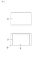
- FIG. 2 is a diagram showing a front surface and a back surface of the display device 100.
- the display device 100 is a movable terminal device that includes a display unit 101 and first and second imaging devices 102 and 103.
- portable terminals such as a smart phone, a tablet terminal, and PDA
- the display device 100 of the present embodiment is a smartphone
- the display unit 101 is a display such as a liquid crystal or an organic EL
- the first imaging device 102 is an in-camera
- the second imaging device 103 is an out-camera. It is.
- application software for executing processing for displaying an image corresponding to the installation position on the display unit 101 is installed in the display device 100. An image displayed on the display unit 101 according to the installation position will be described later.
- the communication unit 20 is connected to an in-vehicle network such as a CAN (Controller Area Network) and receives vehicle information from an in-vehicle device such as an ECU (Engine Control Unit or Electronic Control Unit).
- vehicle information includes speed, engine speed, brake state, steering state, in-vehicle camera image, blinker state, ON / OFF of headlight switch and vehicle width light switch, ON / OFF of ignition switch. Examples include OFF.
- the communication unit 20 is connected to the display device 100 via wireless communication such as Bluetooth (registered trademark) or wired communication such as a wired LAN, and the vehicle received from vehicle identification information such as a vehicle identification number or on-vehicle equipment. Information or the like is transmitted to the display device 100.
- the server 30 is connected to a wireless communication network and transmits / receives information to / from the display device 100.
- this wireless communication network LTE (Long Term Evolution), 3G and other mobile phone communication networks, WiMAX (registered trademark) and other wireless communication networks, and beacons and other highway traffic network wireless communication networks, etc. Can be illustrated.
- the server 30 acquires vehicle identification information, vehicle information, and information on the display device 100 from the display device 100, and sends information necessary for information display processing (hereinafter referred to as display processing information) to the display device 100. Send.
- display processing information information necessary for information display processing
- processing and function allocation between the server 30 and the display device 100 may be set as appropriate.
- the server 30 and the display device 100 cooperate such that the server 30 generates information to be displayed on the display unit 101 of the display device 100 based on the information acquired from the display device 100 and transmits the information to the display device 100. May be constructed.
- FIG. 3 is a block diagram showing a schematic configuration of the vehicle information display system 10.
- the display device 100 includes a communication unit 104, an acceleration sensor 105, and GPS (Global Positioning System) reception in addition to the display unit 101, the first and second imaging devices 102 and 103 described above.
- Machine 106 and processor 110 are examples of the display device 100.
- the communication unit 104 receives the above-described vehicle identification information, vehicle information, and the like from the communication unit 20, transmits vehicle identification information, vehicle information, a GPS signal, which will be described later, and display processing information Receive navigation information.
- the acceleration sensor 105 is a MEMS (Micro Electro Mechanical Systems) 3-axis acceleration sensor or the like, and can measure acceleration in three directions of the X-axis, Y-axis, and Z-axis, and can also measure gravity (static acceleration). it can.
- the GPS receiver 106 receives GPS signals related to absolute position coordinates (latitude / longitude) of the display device 100 from GPS satellites.
- the processor 110 is a computer that includes a ROM 112 that stores a display control program, a CPU 111 as an operation circuit that executes the display control program stored in the ROM 112, and a RAM 113 that functions as an accessible storage device.
- the processor 110 has a function of executing an information acquisition process, an installation position estimation process, a display information generation process, and a display control process, and each process is performed in cooperation with software for realizing each process and the hardware described above. Execute.
- the server 30 includes a communication unit 301, a database 302, and a processor 310.
- the communication unit 301 receives vehicle identification information, vehicle information, GPS signals, and the like, and transmits display processing information, navigation information, and the like with the communication unit 104 of the display device 100.
- the data base 302 stores map information and display processing information.
- the processor 310 is a computer including a ROM 312 in which a display control program is stored, a CPU 311 as an operation circuit that executes the display control program stored in the ROM 312, and a RAM 313 that functions as an accessible storage device.
- the processor 310 has a function of executing information acquisition processing, display processing information extraction processing, and navigation information generation processing, and executes each processing in cooperation with software for realizing each processing and the hardware described above. To do.
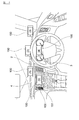
- FIG. 4 and 5 are diagrams for explaining the installation position estimation process of the processor 110.
- FIG. 4 As shown in FIG. 4, when the display device 100 is installed on the dashboard 2 in front of the driver, in front of the meter panel 3 or in front of the center console 4, the first imaging that is an in-camera. The driver's face enters the angle of view of the apparatus 102, and the driver's face is included in the captured image.
- the installation position (1) is the installation position near the center (left side when viewed from the driver) on the dashboard 2 in the right-hand drive vehicle, and the installation position in front of the driver on the dashboard 2 is the installation position ( 2)
- the installation position on the right side when viewed from the driver on the dashboard 2 is referred to as an installation position (3).
- the installation position in front of the meter panel 3 and in front of the driver is referred to as an installation position (4), and the installation position in front of the center console 4 is referred to as an installation position (5).
- the driver adjusts the display unit 101 of the display device 100 so that the driver can easily see the display unit 101.
- the display unit 101 of the display device 100 is arranged perpendicular to the vehicle longitudinal direction.
- the rectangular display device 100 is installed sideways.
- the first imaging device 102 is located on the left side of the display unit 101.
- FIG. 5 shows a position where the driver's face is displayed when the captured image of the first imaging device 102 is displayed on the display unit 101 of the display device 100 installed at the installation positions (1) to (5). It is a figure which shows direction of a driver
- the display device 100 When the display device 100 is installed at the installation position (5) in the lower left as viewed from the driver, the driver's face is displayed in the upper right of the display unit 101. Further, the display device 100 is installed at the installation position (2) on the upper front side when viewed from the driver, and the display device 100 is installed at the installation position (4) on the lower front side when viewed from the driver. In some cases, the display position of the driver's face on the display unit 101 is turned upside down. When the display device 100 is installed at the installation position (4), the driver's face is displayed on the upper left side slightly from the middle of the display unit 101.
- the display device 100 when the display device 100 is installed at the upper right installation position (3) when viewed from the driver and when the display device 100 is installed at the upper left installation position (1) when viewed from the driver.
- the display position of the driver's face on the display unit 101 is reversed left and right.
- the driver's face is displayed slightly on the right side from the middle of the display unit 101.
- the driver's face is displayed on the display unit 101 with the left face facing forward (rightward).
- the driver's face is in a direction in which the right face comes out (leftward). It is displayed on the display unit 101.
- the display device 100 is installed at the installation positions (2) and (4) on the front as viewed from the driver, the driver's face is displayed on the display unit 101 facing the front.
- the installation position in front of the center console 4 is at the lower right when viewed from the driver. Therefore, when the display device 100 is disposed in front of the center console 4 of the left-hand drive vehicle, the driver's face is displayed on the display unit 101 facing left at the upper left of the display unit 101.
- the processor 110 acquires shooting information (ranging information and shot images at the time of AF control) of the first imaging device 102 in the information acquisition processing, and the first imaging device 102 in the installation position estimation processing.
- the position and orientation of the driver's face in the captured image are determined, and the installation position of the display device 100 is estimated based on the determination result.
- the display device 100 when the display device 100 is installed on the dashboard 2, it exists on the windshield or the front side of the windshield at the angle of view of the second imaging device 103 that is an out camera. An object enters, the distance of the windshield or the object existing on the front side of the windshield is measured, and the brightness of the photographing range extending from the dashboard 2 to the front side of the vehicle is measured.
- the meter panel 3 enters the angle of view of the second imaging device 103, the meter panel 3 is measured, and the meter panel 3 The brightness is measured.
- the center console 4 enters the angle of view of the second imaging device 103, the center console 4 is measured, and the center console 4 The brightness is measured.
- the distance to the subject when the display device 100 is installed on the dashboard 2 is longer than the distance to the subject when the display device 100 is installed in front of the meter panel 3 or in front of the center console 4. Become.
- the amount of change in brightness of the shooting range when the display device 100 is installed on the dashboard 2 is the brightness of the shooting range when the display device 100 is installed in front of the meter panel 3 or in front of the center console 4. It becomes larger than the amount of change.
- the processor 110 acquires shooting information (ranging information and brightness at the time of AF control) of the second imaging device 103 in the information acquisition process, and the distance to the subject and the shooting range in the installation position estimation process. Is determined, and the installation position of the display device 100 is estimated based on the determination result.
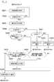
- FIGS. 6 and 7 are flowcharts showing a control procedure of information display processing executed by the vehicle information display system 10 according to the present embodiment.
- the processing routines shown in the flowcharts of these drawings are started when application software installed in the display device 100 is activated.
- the processor 110 of the display device 100 acquires vehicle identification information and vehicle information from the communication unit 20 of the vehicle 1 (step S101).
- the vehicle identification information acquired in this step includes destination information, and identifies the left-hand drive vehicle and right-hand drive vehicle of the vehicle 1 and the equipment of the vehicle 1 based on the destination information. Can do.
- the vehicle information acquired in this step includes at least the steering state, the captured image of the in-vehicle camera, and ON / OFF of the ignition switch.
- the processor 110 acquires detection information of a sensor mounted on the display device 100 (step S102).
- the sensor detection information acquired in this step includes acceleration information detected by the acceleration sensor 105.
- the processor 110 determines whether or not the display device 100 is in a fixed state based on the acceleration information acquired in step S102 (step S103). In this step, the processor 110 determines whether or not the acceleration in the gravity direction (Z-axis direction) detected by the acceleration sensor 105 is equal to or less than a predetermined threshold value. If a negative determination is made in this step, the process returns to step S102. If an affirmative determination is made in this step, the process proceeds to step S104.
- step S104 the processor 110 acquires shooting information from the first imaging device 102, and analyzes the acquired shooting information to thereby determine the position of the driver's face in the shot image and the driver's face as a subject. Is determined.
- the processor 110 acquires shooting information including distance measurement information and brightness information from the second imaging device 103, and calculates the distance to the subject and the amount of change in brightness of the shooting range (step S105). .
- the processor 110 determines whether or not the driver's face is located at the upper right of the captured image of the first imaging device 102 (step S106). If the determination is affirmative, the processor 110 is installed. The position is estimated as the installation position (5) (step S107). That is, the installation position (5) that is relatively far away from the driver's front is estimated based on the position of the driver's face in the captured image of the first imaging device 102. On the other hand, if a negative determination is made in step S106, the process proceeds to step S201 in FIG.
- the display device 100 In the case where the display device 100 is installed in front of the center console 4 of the left-hand drive vehicle, it is determined whether or not the driver's face is located at the upper left of the captured image of the first imaging device 102, When an affirmative determination is made, the installation position of the display device 100 is estimated to be in front of the center console 4.
- the display device 100 when the display device 100 is installed at the installation positions (1) to (4) that are closer to the driver than the installation position (5), the display unit 101 is operated so that the driver can easily see the display unit 101. It is assumed that the person is adjusting the orientation of the display device 100. Therefore, when the display device 100 is installed at the installation positions (1) to (4), there is no possibility that an identifiable difference occurs in the position of the driver's face in the captured image of the first imaging device 102. There is sex. Therefore, the installation position estimated based on the position of the driver's face in the captured image of the first imaging device 102 is only the installation position (5), and the installation positions (1) to (4) are the first. The estimation is based on the orientation of the driver's face in the captured image of the imaging device 102 and the distance measurement information and brightness information of the second imaging device 103.
- step S201 the processor 110 acquires vehicle information from the communication unit 20.
- the vehicle information acquired in this step includes the vehicle speed and the steering angle.
- step S202 the processor 110 determines whether or not the vehicle 1 is traveling in a straight line based on the vehicle speed and the steering angle acquired in step S201 (step S202). If an affirmative determination is made in this step, the process proceeds to step S203, and if a negative determination is made, the process returns to step S201.
- step S202 the processor 110 determines whether or not the vehicle speed is equal to or higher than a predetermined threshold and the steering angle is equal to or lower than the predetermined threshold.
- the threshold value of the vehicle speed is set to a value at which it can be determined that the vehicle 1 is traveling, such as 10 km / h, for example.
- the steering angle threshold is set to a value such as 10 °, for example, where it can be determined that the vehicle 1 is traveling straight.
- step S203 the processor 110 determines the orientation of the driver's face in the captured image of the first imaging device 102 by analyzing the captured image of the first imaging device 102.
- step S204 the processor 110 determines whether or not the direction of the driver's face determined in step S203 is the front direction (step S204). If an affirmative determination is made in this step, the process proceeds to step S205, and if a negative determination is made in this step, the process proceeds to step S301.
- step S301 the processor 110 determines whether or not the driver's face orientation determined in step S203 is rightward (the left face is facing forward). If an affirmative determination is made in this step, the process proceeds to step S302, and if a negative determination is made in this step, the process proceeds to step S303.
- step S302 the processor 110 estimates the installation position of the display device 100 as the installation position (1).
- step S303 the processor 110 estimates the installation position of the display device 100 as the installation position (3). And it transfers to step S108 of FIG. 6 from step S302, S303.
- the processor 110 estimates the installation position of the display device 100 as the installation position (1).
- the processor 110 determines the installation position of the display device 100 as the installation position ( 3).
- the processor 110 determines the installation position of the display device 100 as the installation position (2) or the installation position (4) when the orientation of the driver's face in the captured image of the first imaging device 102 is front-facing. Estimated.
- step S205 the processor 110 estimates whether the installation position of the display device 100 is the installation position (2) or (4) based on the distance measurement information and the brightness information of the second imaging device 103. . Specifically, the processor 110 determines whether or not the distance to the subject is greater than or equal to a predetermined threshold and the amount of change in brightness of the shooting range of the second imaging device 103 is greater than or equal to the predetermined threshold.
- the threshold of the distance to the subject is a value obtained by adding a short distance (for example, 10 cm) to the distance between the meter panel 3 or the center console 4 and the display device 100 installed in front thereof, that is, the windshield and the dashboard. 2 is set smaller than the distance from the display device 100 above.
- the threshold value of the brightness change amount in the shooting range is a value obtained by adding a small amount to the brightness change amount of the meter panel 3 or the center console 4, and is set to a smaller value than the brightness change amount outside the vehicle. ing. If an affirmative determination is made in step S205, the process proceeds to step S206. If a negative determination is made in step S205, the process proceeds to step S207.
- step S206 the processor 110 estimates the installation position of the display device 100 as the installation position (2).
- step S207 the processor 110 estimates the installation position of the display device 100 as the installation position (4). And it transfers to step S108 of FIG. 6 from step S206, S207.
- the processor 110 estimates the installation position of the display device 100 as the installation position (4).
- the distance to the subject of the second imaging device 103 is larger than the distance to the meter panel 3 or the center console 4, and the amount of change in the brightness of the shooting range is that of the meter panel 3 or the center console 4.
- the processor 110 estimates the installation position of the display device 100 as the installation position (2).
- step S108 the processor 110 causes the display unit 101 to display information corresponding to the installation position of the display device 100. If the installation position of the display device 100 is the installation position (1) in the upper left as viewed from the driver, for example, has an object such as another vehicle present on the left side of the vehicle 1 detected when the course is changed to the left side? Information on whether or not is displayed, and navigation information (an image substituting the function of in-vehicle navigation) is displayed except when the route is changed to the left side.
- the installation position of the display device 100 is the installation position (2) on the upper front side as viewed from the driver, for example, when passing through an intersection, an image taken in front of the vehicle by the in-vehicle camera is displayed, and other than when passing through the intersection Displays an image substituting for the function of the meter panel 3.
- the installation position of the display device 100 is the installation position (3) on the upper right side when viewed from the driver, for example, an object such as another vehicle existing on the right side of the vehicle 1 is detected when the route is changed to the right side. Information on whether or not it has been displayed is displayed, and navigation information is displayed except when the route is changed to the right. Further, when the installation position of the display device 100 is the installation position (4) on the lower front side as viewed from the driver, for example, an image that substitutes for the function of the meter panel 3 is displayed. Furthermore, when the installation position of the display device 100 is the lower left installation position (5) when viewed from the driver, for example, navigation information is always displayed.
- step S109 acquires vehicle information (ignition switch ON / OFF) (step S109) and determines whether the ignition switch is OFF (step S110). If an affirmative determination is made in step S110, the processor 110 ends the application software and ends the processing. On the other hand, if a negative determination is made in step S110, the process returns to step S108, and the display of information on the display unit 101 is continued.
- the face of the driver is photographed by the first imaging device 102 provided on the side of the display device 100 on which the display unit 101 is provided. Then, the position of the display device 100 is estimated based on the direction of the photographed driver's face. Thereby, the position of the display apparatus 100 arrange
- the position of the display device 100 is determined when the driver's face imaged by the first imaging device 102 is facing right while the vehicle 1 is traveling straight.
- the position on the left side (installation position (1) or installation position (5)) is estimated as viewed from the driver, and the driver's face imaged by the first imaging device 102 during the straight traveling of the vehicle 1 is facing forward.
- the position of the display device 100 is estimated to be the front position (installation position (2) or installation position (4)) as viewed from the driver, and the first imaging device 102 performs the straight traveling of the vehicle 1 by the first imaging device 102.
- the position of the display device 100 is estimated as the right position (installation position (3)) as viewed from the driver.
- the position of the display device 100 is estimated based on the position of the driver's face imaged by the first imaging device 102. Thereby, for example, the position of the display device 100 that is relatively far from the front of the driver, such as before the center console 4, can be estimated.
- the position of the display device 100 is set to the right handle.
- the position of the display device 100 arranged in front of the center console 4 of the right-hand drive vehicle is specified. can do.
- the position of the display device 100 may be estimated to be in front of the center console 4 of the left-hand drive vehicle.
- the vehicle information display system 10 there is a correlation between the installation position of the display device 100 and the distance to the subject on the vehicle front side acquired by the second imaging device 103 on the back side of the display device 100. Therefore, in the vehicle information display system 10 according to the present embodiment, the front side of the vehicle is photographed by the second imaging device 103, and the distance to the subject acquired by the second imaging device 103 is equal to or greater than a predetermined distance. In this case, the position of the display device 100 is estimated on the dashboard 2 (installation positions (1) to (3)), and the distance to the subject acquired by the second imaging device 103 is less than the predetermined distance.
- the position of the display device 100 is estimated to be in front of the front surface (meter panel 3) of the dashboard 2 (installation position (4) or installation position (5)). Thereby, the position of the up-down direction of the display apparatus 100 arrange
- the second imaging device 103 captures the vehicle front side, and the amount of change in brightness of the imaging range acquired by the second imaging device 103 is a predetermined value.
- the position of the display device 100 is estimated on the dashboard 2 (installation positions (1) to (3)), and the amount of change in brightness of the shooting range acquired by the second imaging device 103 is estimated.
- the position of the display device 100 is estimated to be in front of the front surface of the dashboard 2 (installation position (4) or installation position (5)). Thereby, the position of the up-down direction of the display apparatus 100 arrange
- information corresponding to the estimated position of the display device 100 is displayed on the display unit 101.
- the information according to the position can be displayed on the display device 100 arranged at an arbitrary position in front of the driver.
- FIGS. 8 and 9 are flowcharts showing a control procedure of information display processing executed by the vehicle information display system 10 according to another embodiment.
- description is abbreviate
- the processor 110 acquires shooting information including brightness information from the second imaging device 103, and acquires ON / OFF information of the headlamp switch from the communication unit 20 ( Step S401).
- the control of the light amount of the backlight of the meter panel 3 and the control of the display luminance are executed.
- the installation position is the installation position (4), the brightness of the imaging range of the second imaging device 103 changes in conjunction with the ON / OFF of the headlight switch or the vehicle width lamp switch.
- the display device 100 when the brightness of the shooting range of the second imaging device 103 changes even though the headlight switch or the vehicle width lamp switch is not switched ON / OFF, the display device 100 The installation position is not the installation position (4) but the installation position (2).
- the display device 100 when the brightness of the shooting range of the second imaging device 103 does not change while the headlamp switch or the vehicle width lamp switch is not switched ON / OFF, the display device 100 is installed.
- the position is the installation position (4).
- the installation position of the display device 100 is the installation position (4).
- the processor 110 determines whether or not the brightness of the shooting range of the second imaging device 103 changes in conjunction with the ON / OFF switching of the headlamp switch. (Steps S402 to S404). Specifically, the processor 110 determines whether or not the headlight switch has been switched (step S402). If the determination is affirmative, the processor 110 determines whether the second imaging device 103 is switched. It is determined whether or not the brightness of the shooting range has changed in accordance with the change in brightness of the meter panel 3 (step S403).
- step S404 the processor 110 determines whether or not the amount of change in lightness of the shooting range of the second imaging device 103 is less than a predetermined threshold (step S404).
- the lightness change amount threshold is set to a smaller value than the lightness change amount outside the vehicle.
- step S403 If an affirmative determination is made in step S403, the process proceeds to step S207, and if a negative determination is made in step S403, the process proceeds to step S206.
- step S404 the process proceeds to step S207, and when a negative determination is made in step S404, the process proceeds to step S206.
- step S206 the processor 110 estimates the installation position of the display device 100 as the installation position (2).
- step S207 the processor 110 estimates the installation position of the display device 100 as the installation position (4). And it transfers to step S108 of FIG. 8 from step S206, S207. Thereafter, steps S108 to S110 are executed.
- the subject on the vehicle front side is detected by the second imaging device 103 provided on the opposite side of the surface on which the display unit 101 of the display device 100 is provided.
- the display device The position of 100 is estimated to be in front of the meter panel 3.
- the position (installation position (5)) of the display device 100 disposed in front of the center console 4 is based on the position of the driver's face in the captured image of the first imaging device 102.
- the present invention is not limited to this, and the installation position (5) may be estimated based on the orientation of the driver's face in the captured image of the first imaging device 102.
- the position of the display device 100 arranged on the dashboard 2 (installation position (2)) and the position of the display device 100 arranged in front of the meter panel 3 (installation position (4)). ) Is estimated based on the distance measurement information and lightness information of the second imaging device 103, but is not limited thereto, and may be estimated based on only the distance measurement information or only the lightness information.
- information to be displayed on the display device 100 is set according to the estimation result of the installation position of the display device 100, but the use of the estimation result of the installation position of the display device 100 is limited to this. It is not a thing.
- the estimation result of the installation position of the display device 100 may be used for other purposes, such as turning on / off an audio device included in the display device 100 according to the estimation result of the installation position of the display device 100.
Landscapes
- Engineering & Computer Science (AREA)
- Mechanical Engineering (AREA)
- Transportation (AREA)
- Combustion & Propulsion (AREA)
- Chemical & Material Sciences (AREA)
- Theoretical Computer Science (AREA)
- General Physics & Mathematics (AREA)
- Physics & Mathematics (AREA)
- Multimedia (AREA)
- Health & Medical Sciences (AREA)
- General Health & Medical Sciences (AREA)
- Oral & Maxillofacial Surgery (AREA)
- Human Computer Interaction (AREA)
- Computer Vision & Pattern Recognition (AREA)
- Fittings On The Vehicle Exterior For Carrying Loads, And Devices For Holding Or Mounting Articles (AREA)
- Instrument Panels (AREA)
Abstract
Priority Applications (5)
| Application Number | Priority Date | Filing Date | Title |
|---|---|---|---|
| CN201680084798.XA CN109070748B (zh) | 2016-04-20 | 2016-04-20 | 信息处理装置和显示数据决定方法 |
| PCT/JP2016/062489 WO2017183128A1 (fr) | 2016-04-20 | 2016-04-20 | Procédé d'estimation d'emplacement de dispositif terminal, procédé d'affichage d'informations, et dispositif d'estimation d'emplacement de dispositif terminal |
| US16/095,298 US10776641B2 (en) | 2016-04-20 | 2016-04-20 | Information processing device and method of determining an image data displayed on the same |
| JP2018512700A JP6586226B2 (ja) | 2016-04-20 | 2016-04-20 | 端末装置位置推定方法、情報表示方法、及び端末装置位置推定装置 |
| EP16899401.0A EP3446913B1 (fr) | 2016-04-20 | 2016-04-20 | Procédé d'estimation d'emplacement de dispositif terminal, procédé d'affichage d'informations, et dispositif d'estimation d'emplacement de dispositif terminal |
Applications Claiming Priority (1)
| Application Number | Priority Date | Filing Date | Title |
|---|---|---|---|
| PCT/JP2016/062489 WO2017183128A1 (fr) | 2016-04-20 | 2016-04-20 | Procédé d'estimation d'emplacement de dispositif terminal, procédé d'affichage d'informations, et dispositif d'estimation d'emplacement de dispositif terminal |
Publications (1)
| Publication Number | Publication Date |
|---|---|
| WO2017183128A1 true WO2017183128A1 (fr) | 2017-10-26 |
Family
ID=60116706
Family Applications (1)
| Application Number | Title | Priority Date | Filing Date |
|---|---|---|---|
| PCT/JP2016/062489 Ceased WO2017183128A1 (fr) | 2016-04-20 | 2016-04-20 | Procédé d'estimation d'emplacement de dispositif terminal, procédé d'affichage d'informations, et dispositif d'estimation d'emplacement de dispositif terminal |
Country Status (5)
| Country | Link |
|---|---|
| US (1) | US10776641B2 (fr) |
| EP (1) | EP3446913B1 (fr) |
| JP (1) | JP6586226B2 (fr) |
| CN (1) | CN109070748B (fr) |
| WO (1) | WO2017183128A1 (fr) |
Cited By (2)
| Publication number | Priority date | Publication date | Assignee | Title |
|---|---|---|---|---|
| WO2020152786A1 (fr) * | 2019-01-22 | 2020-07-30 | ヤマハモーターパワープロダクツ株式会社 | Véhicule non routier |
| WO2023058145A1 (fr) * | 2021-10-06 | 2023-04-13 | 三菱電機株式会社 | Dispositif de détection d'occupant et dispositif de capture d'image |
Citations (4)
| Publication number | Priority date | Publication date | Assignee | Title |
|---|---|---|---|---|
| JP2008146356A (ja) * | 2006-12-11 | 2008-06-26 | Nissan Motor Co Ltd | 視線方向推定装置及び視線方向推定方法 |
| JP2012104052A (ja) * | 2010-11-12 | 2012-05-31 | Idea Consultants Inc | 推定方法 |
| JP2012214087A (ja) * | 2011-03-31 | 2012-11-08 | Kojima Press Industry Co Ltd | スマートフォンの配置構造 |
| JP2013203170A (ja) * | 2012-03-28 | 2013-10-07 | Honda Motor Co Ltd | 車両への携帯情報端末の取付位置判別方法 |
Family Cites Families (4)
| Publication number | Priority date | Publication date | Assignee | Title |
|---|---|---|---|---|
| JP5278292B2 (ja) * | 2009-11-27 | 2013-09-04 | 株式会社デンソー | 情報提示装置 |
| JP5847058B2 (ja) * | 2012-11-08 | 2016-01-20 | 本田技研工業株式会社 | 車両表示装置 |
| DE102013015634B4 (de) | 2013-09-20 | 2015-06-18 | Audi Ag | Verfahren und System zum Betreiben wenigstens einer Anzeigeeinrichtung eines Kraftwagens sowie Kraftwagen mit einem System zum Betreiben wenigstens einer Anzeigeeinrichtung |
| EP3134847A1 (fr) * | 2014-04-23 | 2017-03-01 | Google, Inc. | Commande d'interface utilisateur à l'aide d'un suivi du regard |
-
2016
- 2016-04-20 WO PCT/JP2016/062489 patent/WO2017183128A1/fr not_active Ceased
- 2016-04-20 EP EP16899401.0A patent/EP3446913B1/fr active Active
- 2016-04-20 US US16/095,298 patent/US10776641B2/en active Active
- 2016-04-20 JP JP2018512700A patent/JP6586226B2/ja active Active
- 2016-04-20 CN CN201680084798.XA patent/CN109070748B/zh active Active
Patent Citations (4)
| Publication number | Priority date | Publication date | Assignee | Title |
|---|---|---|---|---|
| JP2008146356A (ja) * | 2006-12-11 | 2008-06-26 | Nissan Motor Co Ltd | 視線方向推定装置及び視線方向推定方法 |
| JP2012104052A (ja) * | 2010-11-12 | 2012-05-31 | Idea Consultants Inc | 推定方法 |
| JP2012214087A (ja) * | 2011-03-31 | 2012-11-08 | Kojima Press Industry Co Ltd | スマートフォンの配置構造 |
| JP2013203170A (ja) * | 2012-03-28 | 2013-10-07 | Honda Motor Co Ltd | 車両への携帯情報端末の取付位置判別方法 |
Non-Patent Citations (1)
| Title |
|---|
| See also references of EP3446913A4 * |
Cited By (2)
| Publication number | Priority date | Publication date | Assignee | Title |
|---|---|---|---|---|
| WO2020152786A1 (fr) * | 2019-01-22 | 2020-07-30 | ヤマハモーターパワープロダクツ株式会社 | Véhicule non routier |
| WO2023058145A1 (fr) * | 2021-10-06 | 2023-04-13 | 三菱電機株式会社 | Dispositif de détection d'occupant et dispositif de capture d'image |
Also Published As
| Publication number | Publication date |
|---|---|
| CN109070748A (zh) | 2018-12-21 |
| EP3446913A4 (fr) | 2019-04-10 |
| US20190095732A1 (en) | 2019-03-28 |
| JPWO2017183128A1 (ja) | 2019-02-28 |
| EP3446913A1 (fr) | 2019-02-27 |
| JP6586226B2 (ja) | 2020-01-08 |
| EP3446913B1 (fr) | 2024-07-10 |
| CN109070748B (zh) | 2021-11-30 |
| US10776641B2 (en) | 2020-09-15 |
Similar Documents
| Publication | Publication Date | Title |
|---|---|---|
| US9020746B2 (en) | Vehicle-mounted information processing apparatus and information processing method | |
| JP4914726B2 (ja) | 現在位置算出装置、現在位置算出方法 | |
| RU2720591C1 (ru) | Способ отображения информации и устройство управления отображением | |
| JP4801232B1 (ja) | 端末装置、端末装置によって実行される画像表示方法及び画像表示プログラム | |
| US20170120819A1 (en) | Information display control system and method of controlling display of information | |
| US20180350241A1 (en) | Collision determination system, collision determination terminal, and computer program product | |
| CN111243314A (zh) | 信息提供系统、服务器、移动终端、非暂时性存储介质和信息提供方法 | |
| JP7006235B2 (ja) | 表示制御装置、表示制御方法および車両 | |
| JP6186905B2 (ja) | 車載表示装置およびプログラム | |
| JP2019040551A (ja) | 情報処理装置、車両および路側機 | |
| JP6586226B2 (ja) | 端末装置位置推定方法、情報表示方法、及び端末装置位置推定装置 | |
| JP2014203400A (ja) | 車外画像保存装置、及び撮像機能付き携帯端末 | |
| KR101744718B1 (ko) | 차량용 표시 시스템 및 그 제어방법 | |
| WO2014174822A1 (fr) | Unité d'aide à la conduite, appareil d'aide à la conduite, unité de capteur et terminal portatif | |
| JP2015007818A (ja) | ナビゲーション装置、通信装置、ナビゲーション方法、及びナビゲーションプログラム | |
| JP2018073036A (ja) | 画像取得方法、画像表示システム、及びコンピュータプログラム | |
| JP5174942B2 (ja) | 端末装置、端末装置によって実行される画像表示方法及び画像表示プログラム | |
| JP6547788B2 (ja) | 情報処理システム、情報処理装置及びプログラム | |
| JP2018074315A (ja) | 画像表示システム、画像表示方法及びコンピュータプログラム | |
| JP5036895B2 (ja) | 端末装置、端末装置によって実行される画像表示方法及び画像表示プログラム | |
| JP2013217808A (ja) | 車載機器 | |
| JP2012230115A (ja) | 端末装置、端末装置によって実行される画像表示方法及び画像表示プログラム | |
| JP2020087015A (ja) | 路側機、サーバ装置、通信システム、第1路側機、第2路側機、第1電子機器、第2電子機器及び車両 | |
| JP2016045668A (ja) | 情報処理装置、制御方法、プログラム及び記憶媒体 | |
| JP2014071080A (ja) | 車両の移動方向検出装置、及びコンピュータプログラム |
Legal Events
| Date | Code | Title | Description |
|---|---|---|---|
| ENP | Entry into the national phase |
Ref document number: 2018512700 Country of ref document: JP Kind code of ref document: A |
|
| NENP | Non-entry into the national phase |
Ref country code: DE |
|
| WWE | Wipo information: entry into national phase |
Ref document number: 2016899401 Country of ref document: EP |
|
| 121 | Ep: the epo has been informed by wipo that ep was designated in this application |
Ref document number: 16899401 Country of ref document: EP Kind code of ref document: A1 |
|
| ENP | Entry into the national phase |
Ref document number: 2016899401 Country of ref document: EP Effective date: 20181120 |