WO2017183198A1 - Ruban d'élément de fixation et procédé de fabrication d'élément de fixation - Google Patents
Ruban d'élément de fixation et procédé de fabrication d'élément de fixation Download PDFInfo
- Publication number
- WO2017183198A1 WO2017183198A1 PCT/JP2016/062821 JP2016062821W WO2017183198A1 WO 2017183198 A1 WO2017183198 A1 WO 2017183198A1 JP 2016062821 W JP2016062821 W JP 2016062821W WO 2017183198 A1 WO2017183198 A1 WO 2017183198A1
- Authority
- WO
- WIPO (PCT)
- Prior art keywords
- tape
- yarns
- yarn
- heat
- fastener
- Prior art date
- Legal status (The legal status is an assumption and is not a legal conclusion. Google has not performed a legal analysis and makes no representation as to the accuracy of the status listed.)
- Ceased
Links
Images


Classifications
-
- A—HUMAN NECESSITIES
- A44—HABERDASHERY; JEWELLERY
- A44B—BUTTONS, PINS, BUCKLES, SLIDE FASTENERS, OR THE LIKE
- A44B19/00—Slide fasteners
- A44B19/24—Details
- A44B19/34—Stringer tapes; Flaps secured to stringers for covering the interlocking members
-
- A—HUMAN NECESSITIES
- A44—HABERDASHERY; JEWELLERY
- A44B—BUTTONS, PINS, BUCKLES, SLIDE FASTENERS, OR THE LIKE
- A44B19/00—Slide fasteners
- A44B19/42—Making by processes not fully provided for in one other class, e.g. B21D53/50, B21F45/18, B22D17/16, B29D5/00
Definitions
- the present disclosure relates to a fastener tape and a method for manufacturing the fastener tape.
- Patent Document 1 discloses that a thread whose surface is coated with a synthetic resin is used as a warp or a weft so that the tape main part has a mesh-like structure.
- a predetermined number of warps are used for a predetermined width of the fastener tape.
- the weight of the fastener tape is increased, and the cost of the fastener tape is increased.
- reducing the number of warp yarns in the fastener tape causes warp misalignment in the width direction of the fastener tape, and is hardly studied as a practically effective option.
- the fastener tape is a fastener tape (100) having a tape upper surface and a lower surface (101, 102), Including a tape main part (112) including a structure in which the warp (10) and the weft (20) are woven;
- the tape main body portion (112) includes one or more barrier portions (30) that extend along the direction in which the warp yarn (10) extends and restrict displacement of the adjacent warp yarns (10) on both sides,
- the barrier portions (30) are alternately arranged at least on the first linear portions (31) extending so as to appear alternately on the upper and lower surfaces (101, 102) of the tape and on the upper and lower surfaces (101, 102) of the tape.
- the first linear portion (31) and the second linear portion (32) are partially fixed, including the second linear portion (32) extending so as to appear.
- the first and second linear portions (31, 32) are each Lower portions (31a, 32a) straddling the weft yarn (20) on the tape lower surface (102); Upper portions (31c, 32c) straddling the weft yarn (20) on the tape upper surface (101); A first connecting part (31b, 32b) that connects the lower part (31a, 32a) and the upper part (31c, 32c) and extends from the tape lower surface side to the tape upper surface side; The lower part (31a, 32a) and the upper part (31c, 32c) are connected, and includes a second connecting part (31d, 32d) extending from the tape upper surface side to the tape lower surface side, The first connecting portion (31b) of the first linear portion (31) and the second connecting portion (32d) of the second linear portion (32) are fixed, and the first linear portion (31). The second connecting portion (31d) and the first connecting portion (32b) of the second linear portion (32) adhere to each other.
- the direction in which the warp (10) extends in the plane on which the fastener tape (100) exists is the tape length direction
- the direction orthogonal to the direction in which the warp (10) extends is the tape width direction.
- the first and second linear portions (31, 32) alternately form a weft group (25) including two weft portions extending in the tape width direction on either the upper surface or the lower surface (101, 102) of the tape. It extends to straddle.
- the tape main body (112) includes a plurality of barrier portions (30).
- the plurality of barrier portions (30) include first and second barrier portions (30m, 30n), A plurality of warps (10) are provided between the first and second barrier portions (30m, 30n), and the plurality of warps (10) are warps that do not adhere to any adjacent warps (10) ( 10).
- the arrangement density of the plurality of warps (10) between the first and second barrier portions (30m, 30n) is one or more other portions of the tape main portion (112). Smaller than (R1, R3).
- the number of the plurality of warps (10) between the first and second barrier portions (30m, 30n) is one or more other portions of the tape main portion (112) ( Less than the number of the plurality of warps (10) in R1, R3).
- the barrier portion (30) further includes a third linear portion (33) extending so as to appear alternately on the upper surface and the lower surface (101, 102) of the tape, and the third linear shape.
- the part (33) is partially fixed to at least one of the first and second linear parts (31, 32).
- the method for manufacturing a fastener tape includes a first step of supplying a weft thread (20) and a warp thread (10) to manufacture a fastener tape (100) having an upper surface and a lower surface (101, 102) of the tape. At least a plurality of heat fusion yarns (51, 52, 53) are supplied adjacently as warp yarns (10), and non-heat is applied to both sides of the plurality of adjacent heat fusion yarns (51, 52, 53).
- the second step of heating the fastener tape (100) the plurality of adjacent heat fusion yarns (51, 52, 53) are partially fused, and the warp yarns (10
- an additional plurality of heat fusion yarns (54, 55, 56) are supplied adjacently as warp yarns (10), and the adjacent additional heat fusion yarns are provided.
- a warp yarn (10) of a non-heat-sealing yarn is supplied on both sides of the yarn (54, 55, 56).
- the plurality of heat fusion yarns (51, 52, 53) included in the fastener tape (100) heated in the second step are each A lower portion (51a, 52a, 53a) straddling the weft (20) on the lower surface (102) of the tape; An upper portion (51c, 52c, 53c) straddling the weft (20) on the upper surface (101) of the tape; A first connecting portion (31b, 32b) that connects the lower portion (51a, 52a, 53a) and the upper portion (51c, 52c, 53c) and extends from the tape lower surface (102) side to the tape upper surface (101) side; , A second connecting portion (31d, 32d) that connects the lower portion (51a, 52a, 53a) and the upper portion (51c, 52c, 53c) and extends from the tape upper surface (101) side to the tape lower surface (102) side.
- the first connecting portion (52b) of the heat-sealing yarn (52) is fused.
- the warp on both sides can be prevented from being displaced by the barrier portion of the tape main body.
- FIG. 4 is a schematic diagram showing a schematic cross-sectional configuration along IV-IV (a) in FIG. 3 and a schematic cross-sectional configuration along IV-IV (b) in FIG. 3.
- FIG. 1 it is a schematic front schematic diagram showing the structure of the tape main body provided with one barrier portion according to yet another example, and shows the tape upper surface of the fastener tape before the heating step.
- FIG. 1 It is a schematic flowchart which shows the manufacturing method of the fastener tape which concerns on the exemplary form of this indication.
- FIG. 1 shows the example in case the coil element of an example of a fastener element is woven with respect to a fastener tape.
- FIGS. 1 to 10 Each feature included in one or more disclosed embodiments and embodiments is not individually independent. Those skilled in the art can combine the embodiments and / or features without undue explanation. Those skilled in the art can also understand the synergistic effects of such combinations. In principle, duplicate descriptions between the embodiments are omitted.
- the reference drawings are mainly for description of the invention, and may be simplified for convenience of drawing.
- Each fastener stringer 300 includes a fastener tape 100 and a fastener element 200 provided on the side edge 111 of the fastener tape 100.
- a front stop 210 and a rear stop 220 are provided adjacent to the fastener element 200. In some embodiments, one or both of the front stop 210 and the rear stop 220 are omitted.
- the front-rear direction is understood with reference to the moving direction of the slider 400.
- the left and right fastener stringers 300 are closed, and the left and right fastener elements 200 are engaged.
- the slider 400 moves backward, the left and right fastener stringers 300 are opened, and the left and right fastener elements 200 are disengaged.
- the left-right direction is one of the directions orthogonal to the front-rear direction, and is parallel to the tape surface of the fastener tape 100.
- the vertical direction is another one of the directions orthogonal to the front-rear direction, and is orthogonal to the tape surface of the fastener tape 100.
- the fastener tape 100 has a tape upper surface and a lower surface 101, 102, and the approximate thickness of the fastener tape 100 is defined by these.
- the upper and lower surfaces 101 and 102 of the tape are named for convenience.
- the tape upper surface 101 does not necessarily have to be on the side where the upper blade 410 of the slider 400 exists.
- the tape lower surface 102 does not necessarily have to be on the side where the lower wing plate of the slider 400 exists.
- the fastener tape 100 of the left and right fastener stringer 300 has a side edge portion 111 that faces the fastener tape 100 of the other left and right fastener stringer 300.
- the side edge 111 is provided with a core string.
- the fastener tape 100 has a tape main body 112 adjacent to the side edge portion 111.
- the side edge 111 of the fastener tape 100 is provided on the inner side in the left-right direction with respect to the tape main body 112.
- the tape main body 112 is provided on the outer side in the left-right direction with respect to the side edge 111.
- the inner side in the left-right direction is a direction from a point or position on the tape main portion 112 of the fastener tape 100 of the fastener stringer 300 in the left-right direction to a point or position on the side edge 111.
- the outer side in the left-right direction is the direction opposite to the inner side in the left-right direction.
- the fastener element 200 is a coil element in which a monofilament is spirally wound in the illustrated example.
- the fastener element 200 includes an element row in which block-shaped resin elements are arranged at regular intervals in the front-rear direction, or an element row in which metal elements are arranged at regular intervals in the front-rear direction. .
- Various types of fastener elements may be used in various embodiments.
- the illustrated fastener element 200 includes a configuration in which unit structures are continuous along the front-rear direction.
- the unit structure includes an engaging head disposed on the inner side in the left-right direction than the side edge portion 111 of the fastener tape 100, an upper leg portion connected to the upper end of the engaging head and extending outward in the left-right direction, A lower leg connected to the lower end and extending outward in the left-right direction, and an inversion curved so as to join the outer end in the left-right direction of the lower leg to the outer end in the left-right direction of the upper leg of the adjacent basic unit Part.
- the mechanism by which the left and right fastener elements 200 mesh with each other is widely known to those skilled in the art and will not be described.
- the slider 400 includes an upper wing plate 410, a lower wing plate, a connecting column that connects the upper wing plate and the lower wing plate, a pulling attachment column 440 provided on the upper surface of the upper wing plate 410, and a pulling attachment column.
- One of the sliders having a handle 450 attached to 440.
- the left and right fastener elements 200 enter the slider 400 via the left and right front ports and engage with each other when passing through the connecting column of the slider 400.
- the left and right fastener elements 200 engaged with each other come out from the inside of the slider 400 through the rear opening of the slider 400.
- Various types of sliders can be used in various embodiments.
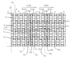
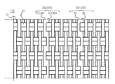
- the fastener tape 100 includes a structure in which warp yarns 10 extending in the front-rear direction and weft yarns 20 extending in the left-right direction are woven.
- the fastener tape 100 includes a tape main body 112 including a structure in which warps 10 extending in the front-rear direction and wefts 20 extending in the left-right direction are woven.
- the fastener tape 100 has a lateral width W100, a longitudinal length L100, and satisfies W100 ⁇ L100.
- the side edge portion 111 has a left-right width W111
- the tape main body portion 112 has a left-right width W112, which satisfies W111 ⁇ W112.
- the direction in which the warp 10 extends in the plane on which the fastener tape 100 exists is the tape length direction
- the direction perpendicular to the direction in which the warp 10 extends is the tape width direction.
- the front-rear direction referred to in the present specification is read in the tape length direction
- the left-right direction is read in the tape width direction to understand the disclosure of the present specification. These reverse readings are also possible.
- the tape main body 112 includes one or more barrier portions 30.
- the barrier portion 30 extends in the direction in which the warp yarn 10 extends, that is, in the tape length direction, and regulates the displacement of the adjacent warp yarns 10 in the tape width direction.
- the plurality of warp yarns 10 arranged adjacent to the barrier portion 30 include warp yarns 10 that do not adhere to any adjacent warp yarns 10. It can be said that the barrier portion 30 is incorporated in the structure of the warp 10 and the weft 20.
- the number of the barrier portions 30 provided in the tape main body 112 is not limited to the illustrated example. In some embodiments, the tape main body 112 is provided with 1, 2, 3, 4, 5, 6, 7, or 8 or more barrier portions 30.
- first and second barrier portions 30m and 30n are provided as two barrier portions.
- the first and second barrier portions 30m and 30n extend in parallel to the tape length direction while maintaining a constant interval in the tape width direction.
- Each barrier portion extends linearly in the tape length direction. Therefore, each barrier portion may be called a linear barrier.
- a third barrier portion 30r is optionally provided as a third barrier portion.
- the third barrier portion 30r is disposed in the vicinity of the fastener element 200. In the vicinity of the fastener element 200, contact between the slider 400 and the fastener tape 100 occurs, and the warp yarn 10 is easily displaced.
- the barrier portion 30 regulates the displacement of the warp yarn 10 adjacent to the left and right in the tape width direction. Therefore, it is allowed to secure a wide arrangement interval of the warps 10 at least in a range adjacent to the barrier portion 30. It is allowed to weave the fastener tape 100 with the reduced number of warps 10, the manufacturing efficiency of the fastener tape 100 can be increased, the weight of the fastener tape 100 can be reduced, or the cost of the fastener tape 100 can be reduced. Or all of this is achieved.
- the barrier portion 30 is constructed by fusing the heat fusion yarns 50 adjacent to the left and right in the tape main body portion 112 at a plurality of locations along the tape length direction.
- the number of heat fusion yarns 50 used to form one barrier portion 30 should not be limited to the illustrated example.
- one, two, three, four, five, six, seven, or eight or more thermal fusing yarns 50 are used to form one barrier portion 30.
- the tape main body 112 is configured by intersecting the warp 10 and the weft 20.
- the tape main body 112 includes a weft set 25 in which wefts 20 extending left and right in the tape width direction are arranged adjacent to each other in the front-rear direction.
- Each weft set 25 includes two weft portions extending in the tape width direction, and ends with a front weft portion and a rear weft portion.
- the left and right outer ends of the front weft portions included in the rear weft set 25 are located at the left and right outer ends of the rear weft portions included in the front weft set 25. It couple
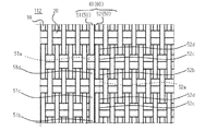
- the tape main body 112 includes a plurality of thermal fusion yarn sets 60, and first and second thermal fusion yarn sets 61 and 62 in order to form a plurality of barrier portions 30.
- the first heat-sealing yarn set 61 includes three heat-sealing yarns 50, and ends up including first to third heat-sealing yarns 51 to 53.
- the second heat fusing yarn set 62 includes three heat fusing yarns 50, and ends up including fourth to sixth heat fusing yarns 54 to 56.
- the number of the heat-fusible yarns 50 included in the first heat-fusible yarn set 61 is greater or less than the number of the heat-fusible yarns 50 included in the second heat-welding yarn set 62.
- the first heat fusion yarn 51 and the second heat fusion yarn 52 are adjacent to each other in the tape width direction.
- the second heat fusion yarn 52 and the third heat fusion yarn 53 are adjacent to each other in the tape width direction.
- the first heat fusion yarn 51 and the third heat fusion yarn 53 are arranged adjacent to each other with the second heat fusion yarn 52 interposed therebetween in the tape width direction.
- the same relationship applied to the first to third heat fusion yarns 51 to 53 applies to the fourth to sixth heat fusion yarns 54 to 56.
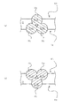
- each heat-sealing yarn 50 extends in the front-rear direction while lifting and sinking in units of 25 weft sets.
- the fact that the heat fusion yarn 50 is lifted means that the heat fusion yarn 50 rises from the tape lower surface 102 side to the tape upper surface 101 side.
- the sinking of the thermal fusion yarn 50 means that the thermal fusion yarn 50 descends from the tape upper surface 101 side to the tape lower surface 102 side.
- the extending modes in the front-rear direction of the two adjacent heat-bonding yarns 50 are not the same.
- the second heat-sealing yarn 52 straddles it on the tape lower surface 102 side.
- the second heat fusion yarn 52 straddles it on the tape upper surface 101 side. It should be noted that it is not always necessary for the two adjacent heat-bonding yarns 50 to rise and fall in a complementary manner.
- the first heat fusion yarn 51 and the second heat fusion yarn 52 extend so as to appear alternately on the upper surface 101 of the tape, Similarly, it extends so as to appear alternately on the lower surface 102 of the tape.
- the second heat fusion yarn 52 and the third heat fusion yarn 53 extend so as to alternately appear on the tape upper surface 101 and similarly extend so as to appear alternately on the tape lower surface 102. Since the first heat fusion yarn 51 and the third heat fusion yarn 53 rise and fall in synchronization, the first heat fusion yarn 51 and the third heat fusion yarn 53 appear together on the upper surface 101 of the tape. And so as to appear together on the lower surface 102 of the tape.
- the region where the first to third heat fusion yarns 51 to 53 are arranged is called a first heat fusion yarn arrangement region, and the fourth to sixth heat fusion yarns 54 to 56 are arranged.
- This area may be referred to as a second heat fusion yarn arrangement area.
- three or more warp yarns 10 are arranged between the third heat fusion yarn 53 and the fourth heat fusion yarn 54. These three or more warps 10 do not adhere to one or both adjacent warps 10.
- five warp yarns 10 are arranged between the third heat fusion yarn 53 and the fourth heat fusion yarn 54. Each of these five warps 10 does not adhere to one or both adjacent warps 10.
- a plurality of warp yarns 10 are arranged on the opposite side of the first thermal fusion yarn 51 to the second thermal fusion yarn 52 and the opposite side of the sixth thermal fusion yarn 56 to the fifth thermal fusion yarn 55.
- the first heat-sealing yarn 51 connects the lower portion 51a straddling the weft assembly 25 on the tape lower surface 102 side, the upper portion 51c straddling the weft assembly 25 on the tape upper surface 101 side, and the lower portion 51a and the upper portion 51c.
- a first connecting portion 51b extending from the tape upper surface 101 toward the front side, a lower portion 51a and an upper portion 51c, and a second connecting portion 51d extending from the tape upper surface 101 side toward the tape lower surface 102 toward the front side.
- the first heat-fusible yarn 51 has a unit structure of these portions 51a to 51d continuously in the front-rear direction.
- the second heat-sealing yarn 52 connects the lower portion 52a straddling the weft assembly 25 on the tape lower surface 102 side, the upper portion 52c straddling the weft assembly 25 on the tape upper surface 101 side, and the lower portion 52a and the upper portion 52c.
- a first connecting portion 52b extending from the tape upper surface 101 toward the front side, a lower portion 52a and an upper portion 52c are connected, and a second connecting portion 52d extending from the tape upper surface 101 side toward the tape lower surface 102 toward the front side is included.
- the second heat-bonding yarn 52 is composed of the unit structures of these portions 52a to 52d continuously in the front-rear direction.
- the third heat fusion yarn 53 connects the lower portion 53a straddling the weft set 25 on the tape lower surface 102 side, the upper portion 53c straddling the weft set 25 on the tape upper surface 101 side, and the lower portion 53a and the upper portion 53c.
- a first connecting portion 53b extending from the tape upper surface 101 toward the front side, a lower portion 53a and an upper portion 53c, and a second connecting portion 53d extending from the tape upper surface 101 side toward the tape lower surface 102 toward the front side.
- the third heat-bonding yarn 53 is composed of the unit structures of these portions 53a to 53d continuously in the front-rear direction.
- the description of the first to third heat fusion yarns 51 to 53 applies to the fourth to sixth heat fusion yarns 54 to 56 as well.
- 1st connection part 51b of the 1st heat fusion yarn 51 and 2nd connection part 52d of the 2nd heat fusion yarn 52 are arranged adjacent to right and left in the tape width direction.
- the second connecting portion 51d of the first heat-sealing yarn 51 and the first connecting portion 52b of the second heat-sealing yarn 52 are arranged adjacent to each other in the tape width direction.
- the 1st connection part 52b of the 2nd heat-fusion yarn 52 and the 2nd connection part 53d of the 3rd heat-fusion yarn 53 are distribute
- the second connecting portion 52d of the second heat-sealing yarn 52 and the first connecting portion 53b of the third heat-sealing yarn 53 are arranged adjacent to each other in the tape width direction.
- the second connection portion 52 d of the second heat fusion yarn 52 is sandwiched between the first connection portion 51 b of the first heat fusion yarn 51 and the first connection portion 53 b of the third heat fusion yarn 53.
- the first connection portion 52 b of the second heat fusion yarn 52 is sandwiched between the second connection portion 51 d of the first heat fusion yarn 51 and the second connection portion 53 d of the third heat fusion yarn 53.
- the same relationship applied to the first to third heat fusion yarns 51 to 53 applies to the fourth to sixth heat fusion yarns 54 to 56.
- each heat fusion yarn 50 partially fixed to the adjacent heat fusion yarn 50 is described as a linear portion of the constituent elements of the barrier portion 30.
- the tape main portion 112 has linear portions 31 to 36 corresponding to the heat fusion yarns 51 to 56.
- Each of the linear portions 31 to 36 has a basic structure that is the same as that of each of the heat fusion yarns 51 to 56.
- the first linear portion 31 connects the lower portion 31a straddling the weft assembly 25 on the tape lower surface 102 side, the upper portion 31c straddling the weft assembly 25 on the tape upper surface 101 side, and the lower portion 31a and the upper portion 31c.
- a first connecting portion 31b extending from the side toward the tape upper surface 101 toward the front, a lower portion 31a and an upper portion 31c, and a second connecting portion 31d extending from the tape upper surface 101 toward the tape lower surface 102 toward the front. .
- the second linear portion 32 connects the lower portion 32a straddling the weft assembly 25 on the tape lower surface 102 side, the upper portion 32c straddling the weft assembly 25 on the tape upper surface 101 side, and the lower portion 32a and the upper portion 32c.
- a first connecting portion 32b extending toward the front side on the tape upper surface 101 side, a lower portion 32a and an upper portion 32c are connected, and a second connecting portion 32d extending frontward from the tape upper surface 101 side to the tape lower surface 102 side is included.
- the third linear portion 33 connects the lower portion 33a straddling the weft assembly 25 on the tape lower surface 102 side, the upper portion 33c straddling the weft assembly 25 on the tape upper surface 101 side, and the lower portion 33a and the upper portion 33c.
- a first connecting portion 33b extending toward the front side on the tape upper surface 101 side, a lower portion 33a and an upper portion 33c are connected, and a second connecting portion 33d extending forward from the tape upper surface 101 side to the tape lower surface 102 side is included.
- the first connecting portion 31b of the first linear portion 31 and the second connecting portion 32d of the second linear portion 32 that are adjacent to each other in the tape width direction are fixed.
- the second connecting portion 31d of the first linear portion 31 and the first connecting portion 32b of the second linear portion 32 adjacent to each other in the tape width direction are fixed.
- the fixing portions of the first connecting portions 32b are alternately provided in the tape length direction.
- the first connecting portion 32b of the second linear portion 32 and the second connecting portion 33d of the third linear portion 33 adjacent to each other in the tape width direction are fixed.
- the second connecting portion 32d of the second linear portion 32 and the first connecting portion 33b of the third linear portion 33 adjacent to each other in the tape width direction are fixed.
- the first connecting portion 32 b of the second linear portion 32 and the fixing portion of the second connecting portion 33 d of the third linear portion 33, and the second connecting portion 32 d of the second linear portion 32 and the third linear portion 33 of The fixing portions of the first connecting portions 33b are alternately provided in the tape length direction.
- the fourth to sixth linear portions 34 to 36 are configured in the same manner as the first to third linear portions 31 to 33.
- the first connecting portion 31b of the first linear portion 31 and the first connecting portion 33b of the third linear portion 33 are also fixed. Accordingly, the first connecting portion 31b of the first linear portion 31, the second connecting portion 32d of the second linear portion 32, and the first connecting portion 33b of the third linear portion 33 form one fixing portion. .
- the second connecting portion 31d of the first linear portion 31 and the second connecting portion 33d of the third linear portion 33 are also fixed. Accordingly, the second connecting portion 31d of the first linear portion 31, the first connecting portion 32b of the second linear portion 32, and the second connecting portion 33d of the third linear portion 33 form one fixing portion. . In some embodiments, the first linear portion 31 and the third linear portion 33 are not directly fixed.
- the fourth to sixth linear portions 34 to 36 are configured in the same manner as the first to third linear portions 31 to 33.
- the displacement in the tape width direction of the warp yarn 10 adjacent to the barrier portion 30 in the tape width direction is preferably prevented by the barrier portion 30. Is done. Thereby, it is allowed to reduce the arrangement density of the warps 10 in the region of the tape main body 112 adjacent to the barrier portion 30.
- adjacent portions of the heat-sealing yarn are fixed to form a fixing portion, and the fixing portion is arranged in the tape length direction, thereby providing a stronger barrier portion 30.
- the number of warp yarns 10 in the region R2 between the first barrier portion 30m and the second barrier portion 30n shown in FIG. Less than the number of warps 10 in the region R1 and / or the region R3 adjacent to R2.
- the region R1 is a region between the second barrier portion 30n and the fastener element 200.
- the region R3 is a region between the first barrier portion 30m and the side edge portion of the fastener tape 100 where the fastener element 200 is not provided.
- the arrangement density of the warps 10 in the region R2 is smaller than the arrangement density of the warps 10 in the region R1 and / or the region R3.
- the number of warp yarns 10 occupying the unit width in the tape width direction in the region R2 is smaller than the number of warp yarns 10 occupying the same unit width in the tape width direction in the region R1 and / or the region R3.
- the arrangement density of the warps 10 in the region R3 is equal to the arrangement density of the warps 10 in the region R2. In some embodiments, the arrangement density of the warps 10 at the side edge 111 is equal to the arrangement density of the warps 10 in the region R1.
- the inventor of the present application introduces a plurality of heat fusion yarns 50 that are selectively adjacent to a group of warp yarns arranged in the left-right direction when the fastener tape 100 is woven using a loom, contrary to the above-mentioned practice.
- a plurality of the heat fusion yarns 50 arranged adjacent to each other in the tape width direction are partially fused and fixed, and the lateral displacement of the adjacent warp yarns 10 is restricted.
- the significance of constructing the possible barrier portion 30 was found.
- the barrier portion 30 When the barrier portion 30 is formed on the tape main portion 112, the barrier portion 30 is fixed to the weft 20 or the weft set 25 more strongly than the warp 10. Therefore, the displacement of the warp yarn 10 adjacent to the barrier portion 30 in the tape width direction is suitably restricted.
- the warp yarns 10 can be arranged sparsely in either the left or right region of the barrier portion 30 or in both regions.
- the number of heat-sealing yarns 50 introduced into the tape main body 112 is smaller than the number of warp yarns 10 of the non-heat-sealing yarn included in the tape main body 112 of the fastener tape 100.
- the heat-sealing yarn 50 is usually more expensive than the non-heat-sealing warp yarn 10, and stricter temperature control may be required for storage.
- each barrier portion 30 is composed of three heat-sealing yarns 50, and a total of six heat-sealing yarns 50 are used, which increases the manufacturing cost of the fastener tape. It has been avoided.
- the heat-bonding yarn 50, the barrier portion 30, and / or the linear portion exhibit a color different from that of the warp yarn 10.
- design property can be simultaneously provided to the fastener tape 100.
- the heat fusion yarn 50 includes a core and a clad covering the core.
- the core is made of a heat resistant material.
- the cladding includes a heat melting material.
- the heat fusion yarn 50 is a solid linear body made of a heat melting material.
- the warp yarn 10 is formed by twisting a large number of thin yarns. In this case, the heat fusion yarn 50 is less resistant to the needle than the warp yarn 10.
- the heat fusion yarn 50, the barrier portion 30, and / or the linear portion exhibits a different color from the warp yarn 10, otherwise a needle that allows left-right displacement of the warp yarn 10 adjacent to the barrier portion 30. It is possible to reduce the risk of damage to the barrier portion 30 and the linear portion.
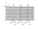
- FIG. 5 shows that three sets of adjacent heat-bonding yarn sets 61 to 63 are woven into the tape main body 112 in order to introduce the three barrier portions 30 into the tape main body 112. Even in such a case, the same effect as described above can be obtained.
- 6 and 7 show an example in which each barrier portion 30 is composed of two heat-sealing yarns 50. Even in such a case, the same effect as described above can be obtained.
- FIG. 8 shows an example in which one barrier portion 30 formed from two heat-sealing yarns 50 is introduced into the tape main body 112. Even in such a case, the same effect as described above can be obtained.
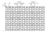
- FIG. 9 shows an example in which adjacent heat-bonding yarns 50 extend back and forth in different modes. Even in such a case, the same effect as described above can be obtained. Specifically, in FIG. 9, the first heat fusion yarn 51 floats and sinks every two weft sets 25, while the second heat fusion yarn 52 rises and sinks every one weft set 25.
- the upper part of the first heat fusion yarn 51 straddling the weft set 25 on the tape upper surface 101 side and the upper part of the second heat fusion yarn 52 straddling the weft set 25 on the tape upper surface 101 side are also fused and fixed to each other. .
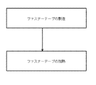
- FIG. 10 shows a method for manufacturing the fastener tape 100.
- the fastener element 200 is a coil element, it is incorporated into the fastener tape 100 when the fastener tape 100 is woven, or is sewn to the side edge 111 of the fastener tape 100 after the fastener tape 100 is woven.
- the fastener element 200 is a resin or metal element, the fastener element 200 is provided on the side edge 111 of the fastener tape 100 by a known method after the fastener tape 100 is woven.
- the method for manufacturing the fastener tape 100 includes a step of manufacturing the fastener tape and a step of heating the fastener tape.
- a fastener element is provided at the side edge of the fastener tape between the step of manufacturing the fastener tape and the step of heating the fastener tape.
- fastener elements are provided on the side edges of the fastener tape.
- the process which manufactures a fastener tape can use the loom currently used widely. By setting the weft and the warp to the loom and operating the loom, the illustrated example of the fastener tape can be manufactured.
- At least a plurality of heat fusion yarns 51 to 53 are supplied as warp yarns 10 adjacent to each other, and warp yarns 10 of non-heat fusion yarns are provided on both sides of the plurality of adjacent heat fusion yarns 51 to 53. Supplied.
- a plurality of additional heat fusing yarns 54-56 are fed adjacently as warp yarn 10, and non-heat fusing yarn warps on either side of the adjacent plurality of heat fusing yarns 54-56. 10 is supplied.
- the heat fusion yarn set 60 includes three heat fusion yarns.
- the first to third heat fusion yarns 51 to 53 are supplied adjacent to each other, and the non-heat fusion yarn warp yarn 10 is supplied on both sides of the first to third heat fusion yarns 51 to 53 arranged adjacent to each other. .
- a plurality of heat fusion yarn sets 60 are supplied.
- the fourth to sixth heat fusion yarns 54 to 56 are supplied adjacent to each other, and the fourth to sixth heat fusion yarns 54 to 56 arranged adjacent to each other are supplied.
- the non-heat-sealed warp yarn 10 is supplied.
- Three or more warp yarns 10 are supplied between the first to third heat fusion yarns 51 to 53 arranged adjacent to each other and the fourth to sixth heat fusion yarns 54 to 56 arranged adjacent to each other.
- the plurality of adjacent heat-sealing yarns 50 are partially fused to form a barrier portion 30 that prevents the displacement of the non-heat-sealing warp yarns 10.
- the heating temperature and the heating time are appropriately set in consideration of the material of the heat fusion yarn, the material of the weft and the warp.
- the first to third heat fusion yarns 51 to 53 are partially fixed to each other.
- the first connection portion 51b of the first heat fusion yarn 51 and the second connection portion 52d of the second heat fusion yarn 52 are fixed.
- the second connecting portion 51d of the first heat-sealing yarn 51 and the first connecting portion 52b of the second heat-sealing yarn 52 are fixed.
- the first connection portion 52b of the second heat fusion yarn 52 and the second connection portion 53d of the third heat fusion yarn 53 are fixed.
- the second connecting portion 52d of the second heat-sealing yarn 52 and the first connecting portion 53b of the third heat-sealing yarn 53 are fixed. Regarding the adjacent first heat fusion yarn 51 and third heat fusion yarn 53, the first connection portion 51b of the first heat fusion yarn 51 and the first connection portion 53b of the third heat fusion yarn 53 are fixed. The second connecting portion 51d of the first heat-sealing yarn 51 and the second connecting portion 53d of the third heat-sealing yarn 53 are fixed. Similarly, the fourth to sixth heat fusion yarns 54 to 56 are partially fixed to each other.
- the first and second heat fusion yarns 51 and 52 are partially fixed to each other.
- the first connection portion 51b of the first heat fusion yarn 51 and the second connection portion 52d of the second heat fusion yarn 52 are fixed.
- the second connecting portion 51d of the first heat-sealing yarn 51 and the first connecting portion 52b of the second heat-sealing yarn 52 are fixed.
- FIG. 11 shows an example in which a coil element as an example of a fastener element is woven into a fastener tape.
- the leg portions of the coil element 200 are fastened by a plurality of warps 10, and the side edges 111 of the fastener tape 100 are woven by the double pick wefts 20.
- the above-described steps or operations are performed so that the engaging head of the coil element 200 protrudes from the side edge portion 111.
- the coil element 200 is woven into the fastener tape 100 with one pick and one element.
- One element described here means one element of the coil element 200.
- the density of the wefts 20 in the fastener tape 100 is reduced, and the crossing density of the warp yarns 10 and the weft yarns 20 is also reduced. There is a risk.
- one or more barrier portions 30 are provided in the fastener tape 100, and it is possible to effectively cope with such a case.
- the upper and lower legs of one element of the coil element 200 are arranged between the weft sets 25 adjacent in the front-rear direction.
- the upper leg portion and the lower leg portion are coupled to each other via an engagement head that is formed to be wide on the left and right inner sides.
- An upper leg portion of an element is coupled to a lower leg portion of an adjacent element through a folded portion.
- the coil element 200 is constructed by a series of such basic elements.
Landscapes
- Woven Fabrics (AREA)
- Slide Fasteners (AREA)
Abstract
L'invention concerne un ruban d'élément de fixation (100) qui comporte des surfaces supérieure et inférieure de ruban (101, 102). Le ruban d'élément de fixation (100) comprend une partie principale de ruban (112) qui a une structure dans laquelle des chaînes (10) et des trames (20) sont tissées. La partie principale de ruban (112) s'étend dans la direction dans laquelle les chaînes (10) s'étendent, et comprend au moins une partie barrière (30) qui limite le déplacement de chaînes adjacentes (10) sur les deux côtés de la partie barrière (30). La partie barrière (30) comprend au moins une première partie linéaire (31) qui s'étend de façon à apparaître alternativement sur les surfaces supérieure et inférieure de ruban (101, 102), et une seconde partie linéaire (32) qui s'étend de façon à apparaître alternativement sur les surfaces supérieure et inférieure de ruban (101, 102). La première partie linéaire (31) et la seconde partie linéaire (32) sont partiellement fixées l'une à l'autre.
Priority Applications (3)
| Application Number | Priority Date | Filing Date | Title |
|---|---|---|---|
| CN201680084834.2A CN109068816B (zh) | 2016-04-22 | 2016-04-22 | 拉链带和拉链带的制造方法 |
| PCT/JP2016/062821 WO2017183198A1 (fr) | 2016-04-22 | 2016-04-22 | Ruban d'élément de fixation et procédé de fabrication d'élément de fixation |
| TW106109486A TWI634853B (zh) | 2016-04-22 | 2017-03-22 | Zipper chain cloth and zipper chain cloth manufacturing method |
Applications Claiming Priority (1)
| Application Number | Priority Date | Filing Date | Title |
|---|---|---|---|
| PCT/JP2016/062821 WO2017183198A1 (fr) | 2016-04-22 | 2016-04-22 | Ruban d'élément de fixation et procédé de fabrication d'élément de fixation |
Publications (1)
| Publication Number | Publication Date |
|---|---|
| WO2017183198A1 true WO2017183198A1 (fr) | 2017-10-26 |
Family
ID=60116685
Family Applications (1)
| Application Number | Title | Priority Date | Filing Date |
|---|---|---|---|
| PCT/JP2016/062821 Ceased WO2017183198A1 (fr) | 2016-04-22 | 2016-04-22 | Ruban d'élément de fixation et procédé de fabrication d'élément de fixation |
Country Status (3)
| Country | Link |
|---|---|
| CN (1) | CN109068816B (fr) |
| TW (1) | TWI634853B (fr) |
| WO (1) | WO2017183198A1 (fr) |
Families Citing this family (2)
| Publication number | Priority date | Publication date | Assignee | Title |
|---|---|---|---|---|
| CN111020816A (zh) * | 2019-12-27 | 2020-04-17 | 江苏驰马拉链科技股份有限公司 | 一种阻燃拉链布带及阻燃拉链的制备方法 |
| CN115434136B (zh) * | 2022-10-19 | 2024-02-13 | 东莞市思源织带实业有限公司 | 高弹性织带的分切方法 |
Citations (3)
| Publication number | Priority date | Publication date | Assignee | Title |
|---|---|---|---|---|
| JPS59130517U (ja) * | 1983-02-22 | 1984-09-01 | カラ−フアスナ−工業株式会社 | スライドフアスナ−本体 |
| JPH0542731Y2 (fr) * | 1986-12-02 | 1993-10-27 | ||
| JPH07124005A (ja) * | 1993-11-04 | 1995-05-16 | Ykk Kk | スライドファスナーの製造方法 |
Family Cites Families (15)
| Publication number | Priority date | Publication date | Assignee | Title |
|---|---|---|---|---|
| US4250598A (en) * | 1979-09-10 | 1981-02-17 | Textron Inc. | Woven slide fastener stringer with molded fastening elements |
| JPS5932580B2 (ja) * | 1980-08-08 | 1984-08-09 | ワイケイケイ株式会社 | スライドフアスナ−用編物製支持テ−プ |
| US4425683A (en) * | 1981-10-14 | 1984-01-17 | Yoshida Kogyo K. K. | Separable slide fastener |
| JPH01141611U (fr) * | 1988-03-22 | 1989-09-28 | ||
| JPH0779815A (ja) * | 1993-09-10 | 1995-03-28 | Ykk Kk | スライドファスナー用テープおよびスライドファスナー |
| CA2118199C (fr) * | 1993-10-29 | 1998-07-14 | Muchiji Shimono | Ruban tisse de fermeture a glissiere |
| US5456293A (en) * | 1994-08-01 | 1995-10-10 | Wangner Systems Corporation | Woven papermaking fabric with diagonally arranged pockets and troughs |
| JP2000303298A (ja) * | 1999-04-14 | 2000-10-31 | Ykk Corp | 帯 体 |
| JP3857541B2 (ja) * | 2001-04-25 | 2006-12-13 | Ykk株式会社 | 帯体 |
| JP2003227049A (ja) * | 2002-01-31 | 2003-08-15 | Ykk Corp | 反射性テープの製造方法とその反射性テープ |
| JP2003334108A (ja) * | 2002-05-20 | 2003-11-25 | Ykk Corp | 開離嵌挿具付きスライドファスナー |
| CN103082590B (zh) * | 2009-07-13 | 2015-11-25 | Ykk株式会社 | 编织拉链牙链带 |
| JP5414905B2 (ja) * | 2010-09-29 | 2014-02-12 | Ykk株式会社 | ファスナーチェーン及びスライドファスナー |
| WO2013035193A1 (fr) * | 2011-09-09 | 2013-03-14 | Ykk株式会社 | Ruban de fermeture pour fermeture à glissière et fermeture à glissière |
| CN105442150B (zh) * | 2015-12-22 | 2018-04-17 | 广东溢达纺织有限公司 | 织带及其制备方法 |
-
2016
- 2016-04-22 CN CN201680084834.2A patent/CN109068816B/zh active Active
- 2016-04-22 WO PCT/JP2016/062821 patent/WO2017183198A1/fr not_active Ceased
-
2017
- 2017-03-22 TW TW106109486A patent/TWI634853B/zh active
Patent Citations (3)
| Publication number | Priority date | Publication date | Assignee | Title |
|---|---|---|---|---|
| JPS59130517U (ja) * | 1983-02-22 | 1984-09-01 | カラ−フアスナ−工業株式会社 | スライドフアスナ−本体 |
| JPH0542731Y2 (fr) * | 1986-12-02 | 1993-10-27 | ||
| JPH07124005A (ja) * | 1993-11-04 | 1995-05-16 | Ykk Kk | スライドファスナーの製造方法 |
Also Published As
| Publication number | Publication date |
|---|---|
| TWI634853B (zh) | 2018-09-11 |
| CN109068816A (zh) | 2018-12-21 |
| TW201737832A (zh) | 2017-11-01 |
| CN109068816B (zh) | 2021-06-01 |
Similar Documents
| Publication | Publication Date | Title |
|---|---|---|
| CN103068272B (zh) | 拉链及其制造方法 | |
| CN102713050B (zh) | 用于接合工业用织物两端的铰接式缝合元件 | |
| JP2014512315A5 (fr) | ||
| TWI572794B (zh) | 無端布帶 | |
| WO2012120602A1 (fr) | Fermeture à glissière et procédé de fabrication de cette dernière | |
| WO2017183198A1 (fr) | Ruban d'élément de fixation et procédé de fabrication d'élément de fixation | |
| WO2019106806A1 (fr) | Bande de fixation, demi-chaîne de fermeture, fermeture à glissière, vêtement et procédé de fabrication de vêtement | |
| WO2014010078A1 (fr) | Demi-chaîne de fermeture et fermeture à glissière | |
| WO2012063340A1 (fr) | Fermeture à glissière | |
| JP2023087074A (ja) | スライドファスナー | |
| JP4762113B2 (ja) | 隠しスライドファスナー用ファスナーストリンガー | |
| JP7802969B2 (ja) | 他の部品と関節接合されることが意図された複合部品の製造のための繊維状強化材 | |
| CN114554903A (zh) | 改进的链带、拉链、蒙皮用品及其形成方法 | |
| WO2014013616A1 (fr) | Demi-chaîne de fermeture et fermeture à glissière | |
| WO2014002218A1 (fr) | Renfort de fermeture et fermeture à glissière | |
| CN106968040B (zh) | 拉链用的拉链带 | |
| US9339087B2 (en) | Incorporated slide fastener | |
| CN102821640A (zh) | 拉链带以及拉链条 | |
| JP2014136842A (ja) | 三次元織物の製造方法、三次元織物構造及び織機 | |
| JP2000014413A (ja) | 織り込みスライドファスナー | |
| JP4719033B2 (ja) | 製紙用シーム付きフェルト及びその製造方法 | |
| CN108430252B (zh) | 拉链牙链带和拉链 | |
| US20240315403A1 (en) | Slide fastener | |
| JP2005330616A (ja) | 玉虫様色調を有する織物 | |
| JP4106692B2 (ja) | 布製スラットの製造法 |
Legal Events
| Date | Code | Title | Description |
|---|---|---|---|
| NENP | Non-entry into the national phase |
Ref country code: DE |
|
| 121 | Ep: the epo has been informed by wipo that ep was designated in this application |
Ref document number: 16899470 Country of ref document: EP Kind code of ref document: A1 |
|
| 122 | Ep: pct application non-entry in european phase |
Ref document number: 16899470 Country of ref document: EP Kind code of ref document: A1 |
|
| NENP | Non-entry into the national phase |
Ref country code: JP |