WO2017183392A1 - Système d'imagerie et système d'endoscope - Google Patents
Système d'imagerie et système d'endoscope Download PDFInfo
- Publication number
- WO2017183392A1 WO2017183392A1 PCT/JP2017/012256 JP2017012256W WO2017183392A1 WO 2017183392 A1 WO2017183392 A1 WO 2017183392A1 JP 2017012256 W JP2017012256 W JP 2017012256W WO 2017183392 A1 WO2017183392 A1 WO 2017183392A1
- Authority
- WO
- WIPO (PCT)
- Prior art keywords
- characteristic value
- black spot
- endoscope
- light source
- unit
- Prior art date
- Legal status (The legal status is an assumption and is not a legal conclusion. Google has not performed a legal analysis and makes no representation as to the accuracy of the status listed.)
- Ceased
Links
Images






Classifications
-
- A—HUMAN NECESSITIES
- A61—MEDICAL OR VETERINARY SCIENCE; HYGIENE
- A61B—DIAGNOSIS; SURGERY; IDENTIFICATION
- A61B1/00—Instruments for performing medical examinations of the interior of cavities or tubes of the body by visual or photographical inspection, e.g. endoscopes; Illuminating arrangements therefor
- A61B1/04—Instruments for performing medical examinations of the interior of cavities or tubes of the body by visual or photographical inspection, e.g. endoscopes; Illuminating arrangements therefor combined with photographic or television appliances
- A61B1/045—Control thereof
-
- G—PHYSICS
- G02—OPTICS
- G02B—OPTICAL ELEMENTS, SYSTEMS OR APPARATUS
- G02B23/00—Telescopes, e.g. binoculars; Periscopes; Instruments for viewing the inside of hollow bodies; Viewfinders; Optical aiming or sighting devices
- G02B23/24—Instruments or systems for viewing the inside of hollow bodies, e.g. fibrescopes
Definitions
- the present invention relates to an inspection system and an endoscope system, and more particularly to an inspection system and an endoscope system for inspecting sunspot characteristic values.
- An endoscope system including an endoscope that captures an object inside a subject and an image processing device that generates an observation image of the object captured by the endoscope is widely used in the medical field, the industrial field, and the like. It is used.
- an image sensor such as a CCD image sensor or a CMOS image sensor is often used as a solid-state image sensor for imaging a subject.
- this type of image sensor is often planned to be mounted on multiple types of products (multiple types of endoscopes, etc.), but it is mounted when the image sensor itself is manufactured (that is, at the time of inspection). In many cases, the final product to be determined is undecided. Therefore, there is a possibility that sufficient correction accuracy cannot be obtained only by the inspection at the time of manufacturing the imaging device itself.
- the present invention has been made in view of the above-described circumstances, and it is possible to accurately perform black spot characteristic correction when the image sensor is mounted on a product and used with only information on inspection at the time of manufacturing the image sensor itself.
- An object is to provide an inspection system and an endoscope system.
- An inspection system receives an inspection light source capable of irradiating illumination light based on any one of light source conditions selected from a plurality of light source conditions, and the irradiation light emitted from the inspection light source.
- a plurality of optical lenses having different optical conditions can be selectively installed; and the optical lens installed in the optical lens installation unit is incident on the optical lens and irradiated from the inspection light source.
- An image sensor installation unit that installs an image sensor to be inspected that receives irradiation light; and an inspection light source control unit that controls to selectively switch any one of the plurality of light source conditions for the inspection light source;
- An image sensor control unit for controlling the image sensor installed in the image sensor installation unit; and selectively controlling the plurality of optical conditions relating to the optical lens unit installed in the optical lens installation unit
- a black point characteristic value calculation unit that calculates a black point characteristic value related to the image pickup device based on an image pickup signal related to the image pickup device, and black point characteristic value information related to the black point characteristic value calculated in the black point characteristic value calculation unit are stored. And a storage unit.
- An endoscope system includes an endoscope on which an imaging element that is an object to be inspected in the inspection system, an image processing apparatus that can connect the endoscope, and the image processing apparatus.
- An identification information acquisition unit that acquires first identification information related to the imaging element in the connected endoscope and second identification information related to light source characteristics and optical characteristics in the endoscope; and Of the black spot characteristic value information provided in the image processing apparatus and stored in the storage unit in the inspection system, the first identification information and the second identification information acquired in the identification information acquisition unit
- a black spot characteristic value information acquisition unit that acquires individual black spot characteristic value information corresponding to at least one of the identification information; and the pieces acquired by the black spot characteristic value information acquisition unit provided in the image processing apparatus.
- black spot characteristic value information and a black point characteristic correcting unit that corrects the black point characteristic of the image pickup device becomes the object to be tested in the test system.
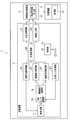
- FIG. 1 is a block diagram showing an electrical main configuration of the inspection system according to the first embodiment of the present invention.
- FIG. 2 is a diagram illustrating a main configuration in a state where an imaging element and an optical lens are installed in the inspection system of the first embodiment.
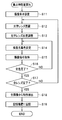
- FIG. 3 is a flowchart showing a black point characteristic value calculation process of the image sensor to be inspected in the inspection system of the first embodiment.
- FIG. 4 is a diagram illustrating an example of how the black spot characteristic is calculated when calculating the black spot characteristic of the image sensor in the inspection system according to the first embodiment.
- FIG. 5 is a diagram illustrating an example of parameters relating to the calculation of the black spot characteristic value of the field sequential type imaging device in the inspection system of the first embodiment.
- FIG. 1 is a block diagram showing an electrical main configuration of the inspection system according to the first embodiment of the present invention.
- FIG. 2 is a diagram illustrating a main configuration in a state where an imaging element and an optical lens are installed in the inspection system of the first embodiment.
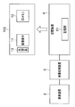
- FIG. 6 is a block diagram illustrating a state in which the black spot characteristic value information stored in the inspection system according to the first embodiment is transferred to an endoscope equipped with an image sensor to be inspected.
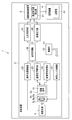
- FIG. 7 is a block diagram illustrating a main configuration of the endoscope system when using an endoscope equipped with an imaging device that is an inspection target of the inspection system of the first embodiment.
- FIG. 8 is a flowchart illustrating a black spot characteristic correction process in the first endoscope system when using an endoscope equipped with an imaging device that is an inspection target of the inspection system of the first embodiment.
- FIG. 9 is a block diagram showing a state in which identification information and black spot characteristic value information stored in the inspection system according to the second embodiment of the present invention are transferred to an endoscope and a server on which an imaging device to be inspected is mounted.
- FIG. FIG. 10 is a block diagram illustrating a main configuration of the second endoscope system when using an endoscope equipped with an imaging device that is an inspection target of the inspection system of the second embodiment.
- FIG. 11 is a diagram illustrating an example of parameters relating to the calculation of the black spot characteristic value of the special-light imaging device.
- FIG. 12 is a diagram illustrating an example of parameters relating to the calculation of the black spot characteristic value of the Bayer image sensor.
- FIG. 1 is a block diagram showing an electrical main configuration of the inspection system according to the first embodiment of the present invention.
- FIG. 2 shows an image sensor and an optical lens installed in the inspection system according to the first embodiment. It is a figure which shows the main structures in the state which carried out.
- an inspection system 1 is connected to an inspection apparatus 2 (see FIG. 2) that inspects the black spot characteristics of an image sensor 11 to be inspected, and the inspection apparatus 2.
- An inspection image processing device 3 for calculating a black spot characteristic value related to the image sensor 11 to be inspected from an output signal from the inspection device 2, and information relating to the black spot characteristic value calculated in the inspection image processing device 3
- the main part is constituted by the storage device 6 for storing.
- the inspection apparatus 2 described above has an imaging element installation unit 2a that can install the imaging element 11 to be inspected, and an optical lens installation that can selectively install a plurality of types of optical lenses 5a and the like (see FIG. 2).
- Unit 2b inspection light source 4 capable of emitting a plurality of types of illumination light
- inspection light source control unit 22 that controls inspection light source 4
- image sensor control unit that controls image sensor 11 installed in image sensor installation unit 2a
- an imaging signal receiving unit 24 that receives an imaging signal from the imaging element 11, an optical lens control unit 25 that controls the optical lens 5a installed in the optical lens installation unit 2b
- the main part is comprised by the control part 21 which manages control.
- the inspection light source 4 in the inspection apparatus 2 described above is controlled by the inspection light source control unit 22 and can irradiate predetermined illumination light toward the optical lens 5a (see FIG. 2) installed in the optical lens installation unit 2b. ing.
- the inspection light source 4 can irradiate any one of a plurality of types of illumination light having different light source conditions.
- the light source condition includes any of a plurality of types of spectroscopy having different wavelengths, and in the first embodiment, R spectroscopy, G spectroscopy, Assume illumination light of B spectroscopy.
- the optical lens installation unit 2b is controlled by the optical lens control unit 25, and can selectively install a plurality of types of optical lenses having different optical conditions, for example, optical lenses 5a, 5b, 5c (see FIG. 2). It has become.
- the optical condition is assumed to be a plurality of lenses having different aperture values or a plurality of lenses having different oblique incident angles.
- the image sensor installation unit 2a can install the image sensor 11 to be inspected (see FIG. 2), and when the image sensor 11 is installed, the image sensor 11 is described later.
- the imaging signal receiving unit 24 is connected.
- the inspection light source control unit 22 is a control unit that controls the above-described plurality of light source conditions related to the inspection light source 4 in the first embodiment under the control of the control unit 21. Specifically, the inspection light source control unit 22 performs switching control of illumination light of R spectroscopy, G spectroscopy, and B spectroscopy corresponding to the surface sequential observation method.
- the image sensor control unit 23 is a control unit that performs drive control of the image sensor 11 under the control of the control unit 21. Specifically, the image sensor control unit 23 is configured such that when the image sensor 11 to be inspected is installed in the image sensor installation unit 2a and predetermined illumination light is emitted from the inspection light source 4 through the optical lens 5a or the like. Then, drive control of the image sensor 11 is performed.
- the imaging signal receiving unit 24 is under the control of the control unit 21 when the imaging device 11 is installed in the imaging device installation unit 2a and predetermined illumination light is emitted from the inspection light source 4 through the optical lens 5a or the like. In addition to fulfilling the function of receiving the imaging signal from the imaging element 11, the imaging signal is output to the subsequent stage.
- the optical lens control unit 25 includes a plurality of types of optical lenses having different optical conditions, for example, optical lenses 5a, 5b, 5c (see FIG. 2) in the optical lens installation unit 2b. Control to be installed selectively.
- the optical lenses 5a, 5b, 5c, etc. are a plurality of lenses having different aperture values (Fno: a, b, c,%) Or oblique incidence angles (a, b, c,). ) Are assumed.
- the optical lens control unit 25 adjusts the position of the optical lens 5a and the like installed in the optical lens installation unit 2b.
- the position adjustment of the installed optical lens 5a and the like may be performed manually.
- the inspection device 2 includes a signal processing unit 26 that processes each signal related to the inspection light source control unit 22, the imaging element control unit 23, the imaging signal reception unit 24, and the like, and the inspection device 2 under the control of the control unit 21.
- An input / output control unit 27 that controls the various input / output signals, and an image output unit 28 that outputs an imaging signal related to the imaging element 11 output from the imaging signal reception unit 24 to the inspection image processing device 3. Further prepare.
- the inspection image processing apparatus 3 described above includes a black spot characteristic value calculation unit 31 that calculates a black spot characteristic value related to the imaging element 11 to be inspected.
- the black spot characteristic value calculation unit 31 calculates the black spot characteristic value from the image pickup signal related to the image pickup element 11 output from the inspection apparatus 2.
- the imaging signal related to the imaging element 11 is an imaging signal under a condition set by changing at least one of the plurality of light source conditions and the plurality of optical conditions.
- the storage device 6 includes a storage unit 61 that stores information on the black spot characteristic value calculated by the black spot characteristic value calculation unit 31.
- the storage unit 61 stores the black point characteristic value information calculated by the black point characteristic value calculation unit 31 as table information in which each condition and the black point characteristic value are associated with each other.
- the black spot characteristic value information is information based on an imaging signal under a condition set by changing at least one of the plurality of light source conditions and the plurality of optical conditions.
- the storage unit 61 stores table information in which each condition and the black spot characteristic value are associated with each other, and this information corresponds to the individual imaging element 11 to be inspected.
- the table information in which each condition associated with the individual image sensor 11 is associated with the black spot characteristic value is stored.
- FIG. 3 is a flowchart showing a black point characteristic value calculating process of the image sensor to be inspected in the inspection system of the first embodiment.
- FIG. 4 is a flowchart of the image sensor in the inspection system of the first embodiment. It is the figure which showed an example of the method of black spot characteristic calculation at the time of black spot characteristic calculation.
- FIG. 5 is a diagram illustrating an example of parameters relating to the calculation of the black spot characteristic value of the field sequential type imaging device in the inspection system according to the first embodiment.
- the image sensor 11 to be inspected is installed in the image sensor installation section 2a of the inspection apparatus 2 (step S11).
- the optical lens control unit 25 selectively installs a plurality of types of optical lenses 5a, 5b, 5c,... With different optical conditions in the optical lens installation unit 2b (step S12). Specifically, the optical lens control unit 25 installs the optical lens having the first optical condition (here, the optical lens 5a having the first aperture value (Fno: a)) in the optical lens installation unit 2b. .
- optical lens control unit 25 adjusts the position of the optical lens 5a installed in the optical lens installation unit 2b to a predetermined position under the control of the control unit 21 (step S13).
- the inspection light source control unit 22 uses the illumination light emitted from the inspection light source 4 as the first light source condition (in this case, R spectrum of each color corresponding to the surface sequential observation method). ) To change the light source color (step S14).
- the image sensor control unit 23 drives the image sensor 11 under the control of the control unit 21, and the image signal reception unit 24 acquires the image signal from the image sensor 11 (step S15).
- the inspection light source control unit 22 under the control of the control unit 21, the inspection light source control unit 22, the imaging element control unit 23, and the imaging signal reception unit 24 repeat the above steps S14 and S15.
- the inspection light source control unit 22 changes the light source color so that the illumination light emitted from the inspection light source 4 is set to the second light source condition (G spectroscopy) (step S14), and imaging is performed.
- the element control unit 23 drives the image pickup device 11 under the control of the control unit 21, and the image pickup signal reception unit 24 acquires an image pickup signal from the image pickup device 11 (step S15).
- the imaging signal receiving unit 24 acquires an imaging signal in a state where the second light source condition (G spectroscopy) and the first optical condition (first aperture value (Fno: a)) are set. It will be.
- the inspection light source control unit 22, the image sensor control unit 23, and the imaging signal reception unit 24 are further controlled by the control unit 21 under the third light source condition (B spectroscopy) and the first optical condition (first optical condition).
- the imaging signal in the state set to the aperture value (Fno: a)) is acquired (repetition of steps S14 and S15).
- step S14 and step S15 are repeated for each color corresponding to the plane sequential observation method, and when acquisition of imaging signals for all colors is completed (step S16), the process proceeds to step S17.
- step S16 when the acquisition of imaging signals related to all light source conditions (R spectroscopy, G spectroscopy, B spectroscopy) corresponding to the first optical condition (first aperture value (Fno: a)) is completed (step S16).
- the control unit 21 controls the optical lens control unit 25 and changes the optical lens according to the changed optical condition (for example, the optical lens is changed to the optical lens 5b having the second aperture value (Fno: b)).
- Acquisition of imaging signals related to all light source conditions (R spectroscopy, G spectroscopy, B spectroscopy) corresponding to the second optical condition is executed (repetition of step S12 to step S16).
- an optical condition with another parameter is assumed as the optical condition. That is, in this embodiment, as another optical condition, for example, lenses having different oblique incident angles (specifically, a first oblique incident angle a, a second oblique incident angle b, etc are assumed. .
- step S17 image pickup signals relating to all combinations (matrix form; see FIG. 5) of all optical conditions (for example, a plurality of aperture values, a plurality of oblique incident angles) and all light source conditions are acquired. Then, all these imaging signals are output from the imaging signal receiving unit 24 and input to the black spot characteristic value calculating unit 31 in the inspection image processing apparatus 3 via the signal processing unit 26 and the image output unit 28.
- the black spot characteristic value calculation unit 31 outputs the imaging signal output from the inspection apparatus 2 side (imaging signal related to all optical conditions and all light source conditions (combination of all conditions) in a matrix).
- black spot characteristic values are calculated from all the images related to the imaging signal (step S18).
- the black spot characteristic value calculation unit 31 tries to detect a pixel whose pixel output is different from a surrounding pixel by a predetermined value or more in the entire pixel of one frame related to the imaging signal, and when there is a detected pixel, Assuming that the pixel is a black point, the output of the pixel is calculated as a black point characteristic value.
- the black point characteristic value calculation unit 31 detects that the predetermined pixel is a black point and calculates the black point characteristic value related to the black point, the information related to the black point characteristic value is transmitted to the storage unit 61 in the storage device 6.
- the information is associated with the image sensor 11 and stored in the storage unit 61 (step S19).
- FIG. 5 is a diagram showing an example of parameters related to the calculation of the black spot characteristic value of the image sensor corresponding to the frame sequential method in the inspection system of the first embodiment.
- a plurality of optical conditions for example, a plurality of aperture values (Fno), a plurality of oblique incident angles) and all light source conditions (R spectroscopy, G spectroscopy, B spectroscopy)
- the black spot characteristic values relating to all combinations of the conditions are associated with the image sensor 11 and stored in the storage unit 61.
- an imaging signal is acquired under a combination of a plurality of optical conditions and a plurality of light source conditions.
- the black spot characteristic value calculation unit 31 outputs pixel outputs according to all the combination conditions. Perform detection.
- the characteristic values in all the conditions are detected for the detected pixel (that is, a black dot).
- the information is stored in the storage unit 61.
- this pixel detection condition does not necessarily require that only pixels that exceed a predetermined threshold be extracted.
- both the pixel A and the pixel B acquire characteristic values even when the pixel B exceeds the detection threshold value of the black spot characteristic while the pixel A does not exceed the detection threshold value. And memorize it.
- FIG. 6 is a block diagram illustrating a state in which the black spot characteristic value information stored in the inspection system according to the first embodiment is transferred to an endoscope equipped with an image sensor to be inspected.
- the image sensor 11 inspected by the inspection system 1 of the present embodiment is mounted on a predetermined endoscope (for example, an endoscope 102 to be described later).
- a predetermined amount is stored from the storage unit 61 in the inspection system 1.
- Information is transferred to an ID memory 12 in the endoscope 102 (the ID memory 12 will be described in detail later).
- table information stored in the storage unit 61 that is, the conditions relating to the plurality of light source conditions and the plurality of optical conditions are associated with the black spot characteristic values.
- individual black spot characteristic value information corresponding to the endoscope 102 on which the imaging device 11 to be inspected is mounted is transferred to the ID memory 12.
- the inspection system 1 of the first embodiment when the table information is transferred from the storage unit 61 to the ID memory 12, the light source characteristics (for example, the endoscope 102 on which the imaging element 11 is mounted (for example, And the black spot characteristic value information relating to the light source condition and the optical condition specific to the endoscope 102 are transferred to the ID memory 12 by acquiring information such as the optical characteristics and the like. It has become.
- all the black spot characteristic value information associated with the image sensor 11 mounted on the endoscope 102 in other words, for the image sensor 11, a combination condition of the plurality of optical conditions and a plurality of light source information.
- the black spot characteristic value information calculated by the above may be transferred to the ID memory 12 as information associated with the image sensor 11.
- the light source characteristics related to the endoscope 102 (as described above, even if the type of observation method is used).
- the light spot conditions specific to the endoscope 102 and the black spot characteristic value information related to the optical conditions are extracted.
- FIG. 7 is a block diagram showing the main configuration of the endoscope system when using an endoscope equipped with an imaging device that is an inspection target of the inspection system of the first embodiment. It is the flowchart which showed the black point characteristic correction process in the 1st endoscope system at the time of using the endoscope which mounts the imaging device which is a test object of the inspection system of 1st Embodiment.
- the endoscope system 101 includes an endoscope 102 that observes and images a subject, and a video processor 103 that is an image processing apparatus that is connected to the endoscope 102 and that inputs the imaging signal and performs predetermined image processing. And a light source device 104 that supplies illumination light for illuminating the subject, and a monitor device 105 that displays an observation image corresponding to the imaging signal.
- the endoscope 102 is mounted with the image pickup device 11 that is the inspection target of the inspection system 1 described above.
- the endoscope 102 includes an illumination unit 14 formed at the tip of a light guide (not shown) extending from the light source device 104 and illumination light emitted from the illumination unit 14.
- ID memory that can store the optical system 13 that receives the reflected light of the subject, the image pickup device 11 disposed on the imaging surface of the optical system 13, and unique identification information related to the endoscope 102, etc. 12 and.
- the optical system 13 receives reflected light related to the subject according to predetermined illumination light (frame sequential light) emitted to the subject by the illumination unit 14. It has become.
- the image pickup device 11 is configured by a CMOS image sensor, and the light receiving unit includes photodiodes that are a plurality of photoelectric conversion units that photoelectrically convert light according to incident light to generate signal charges. And a plurality of pixels for generating and outputting an imaging signal based on the signal charges generated in the photoelectric conversion unit.
- the imaging device 11 is a known circuit that performs predetermined processing on the imaging signal, and includes a known CDS (Correlation Double Sampling) circuit, an analog / digital converter (ADC), and the like.
- An AFE analog front end
- TG timing generator
- the imaging element 11 photoelectrically converts the light incident on each pixel in the photoelectric conversion unit and outputs a predetermined imaging signal.
- the ID memory 12 in the endoscope 102 is composed of, for example, a non-volatile memory, and is used for identifying information unique to the endoscope 102, for example, optical characteristic information related to the optical system 13, illumination light emitted from the illumination unit 14. Such light source characteristic information, individual information of the image sensor 11 itself, and the like are stored.
- the ID memory 12 is associated with the imaging element 11 described above together with the identification information.
- the table information individual black spot characteristic value information unique to the endoscope 102 is stored.
- the table information (that is, the plurality of the plurality of pieces of information) stored in the storage unit 61 in the inspection system 1 and associated with the imaging device 11 at the time of manufacturing the endoscope 102 on which the imaging device 11 is mounted.
- the light spot condition corresponding to the optical characteristic and the light source characteristic in the endoscope 102 and the black spot characteristic value relating to the optical condition.
- Information is transferred to the ID memory 12.
- the video processor 103 includes a control unit 131 that controls various circuits in the video processor 103.
- the control unit 131 identifies the endoscope 102 (for example, optical characteristic information related to the optical system 13, light source characteristic information related to illumination light emitted from the illumination unit 14, and individual information about the image sensor 11 itself). It has the identification information acquisition part 131a which acquires.
- control unit 131 associates the black spot characteristic value information associated with the image sensor 11 (that is, table information in which the conditions relating to the plurality of light source conditions and the plurality of optical conditions are associated with the black spot characteristic value).
- the black spot characteristic value information associated with the image sensor 11 that is, table information in which the conditions relating to the plurality of light source conditions and the plurality of optical conditions are associated with the black spot characteristic value.
- the light source condition corresponding to the optical characteristic and the light source characteristic in the endoscope 102 and the individual black spot characteristic value information acquisition unit 131b for acquiring individual black spot characteristic value information related to the optical condition are included.
- both “identification information” and “individual black spot characteristic value information” of the endoscope 102 are stored in the ID memory 12 of the endoscope 102 in this embodiment.
- the identification information acquisition unit 131a acquires the “identification information”
- the black spot characteristic value information acquisition unit 131b acquires the “ The “individual black spot characteristic value information” corresponding to “identification information” is acquired.
- the video processor 103 has an image processing unit 132 that inputs an imaging signal from the endoscope 102 and performs predetermined image processing.
- the image processing unit 132 uses the individual black point characteristic value information acquired by the black point characteristic value information acquiring unit 131b to correct the black point characteristic of the imaging element 11 to be inspected in the inspection system 1. It has a characteristic correction unit 132a.
- the light source device 104 includes a light source 144, a light source driver 142, a rotary filter 146, a drive unit 145, a drive driver 143, and a light source control unit 141.
- the light source 144 is configured using a white LED (Light Emitting Diode), a xenon lamp, or the like, and generates white light under the control of the light source control unit 141.
- a white LED Light Emitting Diode
- a xenon lamp or the like
- the light source driver 142 causes the light source 144 to generate white light by supplying a current to the light source 144 under the control of the light source control unit 141.
- Light generated by the light source 144 is emitted from the illumination unit 14 of the endoscope 102 via the rotary filter 146, a condenser lens (not shown), and the light guide.
- the rotary filter 146 is arranged on the optical path of white light emitted from the light source 144, and transmits only the light having a predetermined wavelength band through the white light emitted from the light source 144 by rotating.
- the rotary filter 146 includes a red filter 146R, a green filter 146G, and a blue filter 146B that transmit light having respective wavelength bands of red light (R), green light (G), and blue light (B).
- R red light
- G green light
- B blue light
- the driving unit 145 rotates the rotation filter 146 based on the synchronization signal transmitted from the video processor 103.
- the drive driver 143 supplies a predetermined current to the drive unit 145 under the control of the light source control unit 141.
- the light source control unit 141 controls the amount of current supplied to the light source 144 according to the dimming signal transmitted from the control unit 131 in the video processor 103. Further, the light source control unit 141 rotates the rotary filter 146 by driving the drive unit 145 via the drive driver 143.
- the light source device 104 is configured using the single light source 144 of white light and the rotation filter 146 as described above in order to support the frame sequential method. By using a plurality of LEDs corresponding to the above, it may be compatible with the field sequential method.
- the monitor device 105 has a function of receiving an in-vivo image generated by the video processor 103 from the video processor 103 via a video cable and displaying it.
- FIG. 8 is a flowchart showing a black spot characteristic correction process in the first endoscope system when using an endoscope equipped with an imaging device that is an inspection target of the inspection system of the first embodiment.
- the identification information acquisition unit 131a in the video processor 103 relates to the endoscope 102 from the ID memory 12 arranged in the endoscope 102.
- the “identification information” is acquired (step S21).
- the identification information acquisition unit 131a acquires optical characteristic information (lens characteristic information) related to the optical system 13 (step S22), and light source characteristic information (photo primary color information) related to illumination light emitted from the illumination unit 14. Is acquired (step S23). Further, the identification information acquisition unit 131a further acquires identification information of the image sensor 11 itself.
- the black spot characteristic value information acquisition unit 131b in the video processor 103 performs black spot characteristic value information associated with the image sensor 11 (that is, the conditions and black spot characteristics related to the plurality of light source conditions and the plurality of optical conditions). Table information in which values are associated with each other), the optical characteristics and the light source conditions corresponding to the light source characteristics in the endoscope 102 and the individual black spot characteristic value information (correction characteristic value information) related to the optical conditions are acquired, and the black spots The characteristic is calculated (step S24).
- the black point characteristic correction unit 132a is calculated by the black point characteristic value information acquisition unit 131b. Based on the black spot characteristics, the imaging signal is corrected for each frame corresponding to each of R spectroscopy, G spectroscopy, and B spectroscopy (step S26).
- a black point correction method in the black point characteristic correction unit 132a a method of multiplying the black point pixel output by the reciprocal of the black point increase / decrease rate calculated by the black point characteristic value information acquisition unit 131b is adopted in this embodiment.
- the black spot characteristic correction unit 132a is output from the endoscope 102 when the endoscope 102 is connected to the video processor 103. Based on the imaging signal, it is determined whether or not the imaging signal is obtained by irradiation with illumination light having any wavelength characteristic.
- the black spot characteristic correcting unit 132a determines whether the imaging signal is generated by the R light, the G light, or the B light (light source), and for each imaging frame according to the determination result.
- the black spot characteristic of the image sensor 11 is corrected using the individual black spot characteristic value information acquired by the black spot characteristic value acquisition unit 131b.
- the optical system A plurality of types of optical lenses 5a, 5b, and 5c having different conditions are selectively installed in the installation unit 2b, and in this state, a plurality of types of illumination light having different light source conditions are irradiated from the inspection light source 4, and the imaging signal receiving unit 24
- the black spot characteristic value calculation unit 31 calculates a black point characteristic value unique to the imaging element 11, stores the calculated unique black spot characteristic value information in the storage unit 61, and further stores the calculated black point characteristic value information from the storage unit 61.
- the information is transferred to the ID memory 12 of the endoscope 102 on which the image sensor 11 is mounted.
- the identification information acquisition unit 131a and the black spot characteristic value information acquisition unit 131b in the video processor 103 acquire identification information and black spot characteristic value information from the ID memory 12, and the black spot characteristic correction unit. Since 132a corrects the black spot characteristics of the image sensor 11, an inspection system for accurately correcting the black spot characteristics when the image sensor is mounted on a product and used with only information on inspection at the time of manufacturing the image sensor itself. And an endoscopic system can be provided.
- the inspection system and the endoscope system according to the first modification of the present embodiment have the plurality of optical points related to all the black spot characteristic value information associated with the image sensor 11, in other words, the image sensor 11.
- the feature is that “all black spot characteristic value information” calculated based on the conditions and the combination conditions of all of the plurality of light source information is transferred to the ID memory 12 as information associated with the image sensor 11.
- the identification information acquisition unit 131a in the video processor 103 connected to the endoscope 102 firstly uses the ID memory 12 provided in the endoscope 102.
- the “identification information” related to the endoscope 102 is acquired.
- the identification information acquisition unit 131a is similar to the endoscope system 101 according to the first embodiment, the identification information related to the endoscope 102, that is, the optical characteristic information (lens characteristic information) related to the optical system 13. , The light source characteristic information (light primary color information) related to the illumination light irradiated from the illumination unit 14, and the identification information of the image sensor 11 itself are also acquired.
- the black spot characteristic value information acquisition unit 131b in the video processor 103 is based on each identification information related to the endoscope 102 acquired by the identification information acquisition unit 131a.
- the “individual black spot characteristic value information” related to the endoscope 102 is extracted from the “all black spot characteristic value information” described above, and the black spot characteristic is calculated.
- the black spot characteristic value information acquisition unit 131b according to the first modification is associated with the imaging element 11 stored in the ID memory 12 based on the identification information acquired by the identification information acquisition unit 131a.
- the optical characteristics and the endoscope 102 “Individual black spot characteristic value information” relating to the light source condition and optical condition corresponding to the light source characteristic is extracted, and the black spot characteristic is calculated.
- the black spot characteristic correction unit 132a is a black spot characteristic value information acquisition unit, as in the first embodiment. Based on the black spot characteristics calculated in 131b, the imaging signal is corrected for each frame corresponding to R spectroscopy, G spectroscopy, and B spectroscopy.
- the black spot characteristic correction when the image pickup device is mounted on a product and used is the information only for the inspection at the time of manufacturing the image pickup device itself. Therefore, it is possible to provide an inspection system and an endoscope system that can accurately perform the above.
- the ID memory 12 in the endoscope 102 includes the light source corresponding to the optical characteristics and the light source characteristics in the endoscope 102. It was assumed that “individual black spot characteristic value information” related to the conditions and optical conditions was stored.
- the storage unit 61 in the inspection system 1 stores all the black spot characteristic value information associated with the image sensor 11, in other words, the combination conditions of the plurality of optical conditions and the plurality of light source information regarding the image sensor 11. Is stored in the ID memory 12 of the endoscope 102, and the light source conditions corresponding to the optical characteristics and the light source characteristics of the endoscope 102 and the “individual” "Spot characteristic value information" has been transferred.
- the ID memory 12 in the endoscope 102 has all the black dots associated with the image sensor 11 mounted on the endoscope 102 as described above.
- Characteristic value information in other words, “all black spot characteristic value information” calculated based on the combination conditions of all of the plurality of optical conditions and the plurality of light source information is transferred for the image sensor 11.
- the “spot characteristic value information acquisition unit 131b” stores “all” stored in the ID memory 12 based on the identification information acquired by the identification information acquisition unit 131a. From the “black spot characteristic value information” (all table information linked to the image sensor 11), the “individual black spot characteristic value information” related to the optical characteristics and the optical conditions in the endoscope 102, and the optical conditions. To extract.
- the black spot characteristic value information acquisition unit 131b includes the endoscope.
- “Individual black spot characteristic value information” relating to the light source condition and the optical condition corresponding to the optical characteristic and the light source characteristic in 102 can be acquired.
- the inspection system and the endoscope system of the second modification As in the first modification, “all black spot characteristic value information” (all table information associated with the image sensor 11) is transferred to the ID memory 12 of the endoscope 102, while the “all black point characteristic value information” is transferred.
- the “spot characteristic value information” does not include the light source condition corresponding to the optical characteristic and the light source characteristic in the endoscope 102 and “individual black spot characteristic value information” related to the optical condition Even in this case, predetermined black point correction is performed.
- the “black spot characteristic value information” stored in the ID memory 12 of the endoscope 102 in the black spot characteristic value information acquisition unit 131b in the video processor 103 Two or more black spot characteristic values approximate to the light source condition and / or the optical condition corresponding to the optical characteristic and the light source characteristic in the endoscope 102 are acquired.
- the black point characteristic correction unit 132a estimates a predetermined black point characteristic value from the two or more approximated black point characteristic value information acquired by the black point characteristic value information acquisition unit 131b. Further, the black spot characteristic correcting unit 132a corrects the black spot characteristic related to the imaging signal (image signal) from the imaging device 11 using the estimated black spot characteristic value.
- the inspection system and the endoscope system of the second modified example the light spot condition and the optical condition corresponding to the optical characteristic and the light source characteristic in the endoscope 102 in the black spot characteristic value information acquisition unit 131b. Even when the “individual black spot characteristic value information” cannot be acquired, the image sensor is included in the product with the information only for the inspection at the time of manufacturing the image sensor itself, as in the first embodiment. It is possible to provide an inspection system and an endoscope system that can accurately correct black spot characteristics when mounted and used.
- FIG. 9 is a block diagram showing a state in which the black spot characteristic value information stored in the inspection system according to the second embodiment of the present invention is transferred to an endoscope and a server equipped with an image sensor to be inspected.
- FIG. 10 is a block diagram showing a main configuration of the second endoscope system when using an endoscope equipped with an imaging device that is an inspection target of the inspection system of the second embodiment.
- the basic configuration of the inspection system and the endoscope system of the second embodiment is the same as that of the first embodiment, and the transfer destination of the black spot characteristic value information stored in the storage unit in the inspection system is different.
- the endoscope system only the acquisition path of the sunspot characteristic value information is different. Accordingly, only the differences from the first embodiment will be described here, and descriptions of common parts will be omitted.
- the storage device 6 includes a storage unit 61 that stores information on the black spot characteristic value calculated by the black spot characteristic value calculation unit 31.
- the storage unit 61 stores the black point characteristic value information calculated by the black point characteristic value calculation unit 31 as table information in which the conditions are associated with the black point characteristic values.
- the storage unit 61 stores table information (black spot characteristic value information) in which each condition associated with the image sensor 11 is associated with the black spot characteristic value.
- the black spot characteristic value information stored in the storage unit 61 is transferred to an external server 106 via a predetermined network.
- all or a part of “all black spot characteristic value information” associated with the image sensor 11 is transferred from the storage unit 61 of the storage device 6 to the server 106. ing.
- the black spot characteristic value information related to the image sensor 11 that is one inspection target is transferred from the storage unit 61 in the inspection system 1 to the server 106.
- the server 106 can also store black spot characteristic value information relating to other imaging elements that are other inspection targets.
- the black spot characteristic value information relating to the other image sensor may be transmitted from the inspection system 1 or may be transmitted from another inspection system.
- identification information of the endoscope 102 (for example, optical characteristic information related to the optical system 13, light source characteristic information related to illumination light emitted from the illumination unit 14, and imaging) The individual information of the element 11 itself, etc.) is stored.
- the black spot characteristic value information When the black spot characteristic value information is transferred from the storage unit 61 of the storage device 6 to the server 106 as described above, the black spot characteristic value information (or individual black spot characteristic value information) is stored in parallel. You may transfer to the ID memory 12 in the endoscope 102.
- FIG. 10 is a block diagram showing the main configuration of the second endoscope system when using an endoscope equipped with an imaging device that is an inspection target of the inspection system of the second embodiment.
- the second endoscope system 201 includes an endoscope 102 that observes and images a subject, and inputs the imaging signal connected to the endoscope 102 to receive a predetermined image.
- a video processor 103 that is an image processing device that performs processing, a light source device 104 that supplies illumination light for illuminating a subject, and a monitor device 105 that displays an observation image according to an imaging signal.
- a server 106 is included.
- the video processor 103 controls various circuits and includes a control unit 131 including an identification information acquisition unit 131a and a black spot characteristic value information acquisition unit 131b.
- the control unit 131 is connected to the server 106 via a predetermined network.
- the identification information acquisition unit 131a includes identification information of the endoscope 102 (for example, optical characteristic information related to the optical system 13, light source characteristic information related to illumination light emitted from the illumination unit 14, And individual information of the image sensor 11 itself).
- the sunspot characteristic value information acquisition unit 131 b is connected to the server 106 via a predetermined network and stores “all sunspot characteristic value information” stored in the server 106. All or part of the data can be read out.
- the black spot characteristic value information acquisition unit 131b performs the black spot characteristic value information associated with the image sensor 11 (that is, each condition relating to the plurality of light source conditions and the plurality of optical conditions). All or part of the table information associated with the black spot characteristic values) can be read out.
- the black spot characteristic value information acquisition unit 131b corresponds to “individual information” related to the “identification information” related to the endoscope 102 acquired by the identification information acquisition unit 131a when the endoscope 102 is connected to the video processor 103.
- the “spot characteristic value information” is read from the server 106.
- the identification information acquisition unit 131a in the video processor 103 acquires the “identification information” related to the endoscope 102 from the ID memory 12 provided in the endoscope 102. To do.
- the identification information acquisition unit 131a acquires optical characteristic information (lens characteristic information) related to the optical system 13, and also acquires light source characteristic information (light primary color information) related to the illumination light emitted from the illumination unit 14. Further, the identification information acquisition unit 131a further acquires identification information of the image sensor 11 itself.
- the black spot characteristic value information acquisition unit 131b in the video processor 103 is connected to the server 106 via a predetermined network, and the black spot characteristic value information associated with the imaging device 11 (that is, the plurality of light source conditions and Among the table information in which each condition related to the plurality of optical conditions is associated with the black spot characteristic value), the optical characteristic and the light source characteristic in the endoscope 102 are determined according to the “identification information” by the identification information acquisition unit 131a. Individual black spot characteristic value information (correction characteristic value information) relating to the corresponding light source condition and optical condition is read, and the black spot characteristic is calculated.
- the black spot characteristic correction unit 132a is a black spot characteristic value information acquisition unit, as in the first embodiment. Based on the black spot characteristics calculated in 131b, the imaging signal is corrected for each frame corresponding to R spectroscopy, G spectroscopy, and B spectroscopy.
- all or part of the “spot characteristic value information” related to the image sensor 11 that has been inspected and acquired by the inspection system 1. Is stored in the external server 106.
- the second embodiment is an essential process in the first embodiment described above, and the black spot characteristic value to the endoscope 102 (the ID memory 12) at the time of manufacturing the endoscope 102 or the like.
- the information transfer process can be omitted, and the effects of the present invention can be realized in a wider range of endoscope systems.
- an observation method using a surface sequential light source is adopted.
- the present invention is not limited to this, and an example of performing PWM control using an LED light source or the like, or a narrow band as special light observation It can also be applied to examples employing observation methods such as light observation (NBI: NarrowBIBand Imaging), infrared light observation (IRI: InfraRed Imaging), or fluorescence observation (AFI: Auto Fluorescence Imaging).
- NBIBand Imaging NarrowBIBand Imaging
- IRI InfraRed Imaging
- AFI Auto Fluorescence Imaging
- FIG. 11 is a diagram illustrating an example of a parameter related to the calculation of the black spot characteristic value of the special-light imaging device
- FIG. 12 is a diagram illustrating an example of the parameter related to the calculation of the black spot characteristic value of the Bayer imaging device. It is.
- the light source condition is narrow as shown in FIG. 11 instead of the surface sequential method in the first embodiment.
- G ′ spectroscopy and B ′ spectroscopy which are band lights, can be applied.
- the light source condition is Instead of the surface sequential method in the first embodiment, as shown in FIG. 12, normal light (white light spectrum (W spectrum)) and special light (NBI spectrum) can be applied.
Landscapes
- Physics & Mathematics (AREA)
- Health & Medical Sciences (AREA)
- Life Sciences & Earth Sciences (AREA)
- Surgery (AREA)
- Optics & Photonics (AREA)
- Biomedical Technology (AREA)
- Medical Informatics (AREA)
- Nuclear Medicine, Radiotherapy & Molecular Imaging (AREA)
- Pathology (AREA)
- Radiology & Medical Imaging (AREA)
- Astronomy & Astrophysics (AREA)
- Engineering & Computer Science (AREA)
- General Physics & Mathematics (AREA)
- Biophysics (AREA)
- Molecular Biology (AREA)
- Heart & Thoracic Surgery (AREA)
- Animal Behavior & Ethology (AREA)
- General Health & Medical Sciences (AREA)
- Public Health (AREA)
- Veterinary Medicine (AREA)
- Endoscopes (AREA)
- Instruments For Viewing The Inside Of Hollow Bodies (AREA)
Abstract
Selon la présente invention, pendant une inspection, un élément de capture d'image 11 d'un objet devant être inspecté est placé dans une unité de placement 2a, après quoi une pluralité de lentilles optiques 5a ... ayant différentes conditions optiques sont sélectivement placées dans une unité de placement 2b. Dans cet état, une pluralité de types de lumière d'éclairage ayant différentes conditions de source de lumière sont rayonnés depuis une source de lumière d'inspection 4, des valeurs caractéristiques de point noir uniques pour l'élément de capture d'image 11 sont calculées par une unité de calcul de valeur caractéristique de point noir 31 sur la base d'un signal d'imagerie obtenu, et des informations de valeur caractéristique de point noir sont stockées dans une unité de stockage 61. En outre, lesdites informations sont transférées de l'unité de stockage 61 vers une mémoire d'identifiant 12 d'un endoscope 102 dans lequel l'élément de capture d'image 11 doit être monté. Pendant l'utilisation, une unité d'acquisition d'informations d'identification 131a et une unité d'acquisition d'informations de valeur caractéristique de point noir 131b dans un processeur vidéo 103 acquièrent des informations d'identification et les informations de valeur caractéristique de point noir depuis la mémoire d'identifiant 12, et une unité de correction de caractéristique de point noir 132a corrige les caractéristiques de point noir de l'élément de capture d'image 11.
Priority Applications (1)
| Application Number | Priority Date | Filing Date | Title |
|---|---|---|---|
| JP2018513083A JPWO2017183392A1 (ja) | 2016-04-22 | 2017-03-27 | 検査システムおよび内視鏡システム |
Applications Claiming Priority (2)
| Application Number | Priority Date | Filing Date | Title |
|---|---|---|---|
| JP2016086420 | 2016-04-22 | ||
| JP2016-086420 | 2016-04-22 |
Publications (1)
| Publication Number | Publication Date |
|---|---|
| WO2017183392A1 true WO2017183392A1 (fr) | 2017-10-26 |
Family
ID=60116099
Family Applications (1)
| Application Number | Title | Priority Date | Filing Date |
|---|---|---|---|
| PCT/JP2017/012256 Ceased WO2017183392A1 (fr) | 2016-04-22 | 2017-03-27 | Système d'imagerie et système d'endoscope |
Country Status (2)
| Country | Link |
|---|---|
| JP (1) | JPWO2017183392A1 (fr) |
| WO (1) | WO2017183392A1 (fr) |
Citations (4)
| Publication number | Priority date | Publication date | Assignee | Title |
|---|---|---|---|---|
| JP2005124036A (ja) * | 2003-10-20 | 2005-05-12 | Pentax Corp | 欠陥画素検出装置、欠陥画素検出方法、及び欠陥画素検出プログラム |
| JP2006026234A (ja) * | 2004-07-20 | 2006-02-02 | Olympus Corp | 生体内撮像装置および生体内撮像システム |
| JP2010130289A (ja) * | 2008-11-27 | 2010-06-10 | Panasonic Corp | 固体撮像装置、半導体集積回路および欠陥画素補正方法 |
| JP2013093695A (ja) * | 2011-10-25 | 2013-05-16 | Canon Inc | 撮像装置及びその制御方法、並びにプログラム |
Family Cites Families (3)
| Publication number | Priority date | Publication date | Assignee | Title |
|---|---|---|---|---|
| JPH0746898Y2 (ja) * | 1989-01-25 | 1995-10-25 | 富士写真光機株式会社 | 内視鏡の接眼レンズ装置 |
| JPH10295637A (ja) * | 1997-04-25 | 1998-11-10 | Olympus Optical Co Ltd | 内視鏡用撮像装置 |
| WO2016056332A1 (fr) * | 2014-10-06 | 2016-04-14 | オリンパス株式会社 | Système d'acquisition d'image |
-
2017
- 2017-03-27 WO PCT/JP2017/012256 patent/WO2017183392A1/fr not_active Ceased
- 2017-03-27 JP JP2018513083A patent/JPWO2017183392A1/ja active Pending
Patent Citations (4)
| Publication number | Priority date | Publication date | Assignee | Title |
|---|---|---|---|---|
| JP2005124036A (ja) * | 2003-10-20 | 2005-05-12 | Pentax Corp | 欠陥画素検出装置、欠陥画素検出方法、及び欠陥画素検出プログラム |
| JP2006026234A (ja) * | 2004-07-20 | 2006-02-02 | Olympus Corp | 生体内撮像装置および生体内撮像システム |
| JP2010130289A (ja) * | 2008-11-27 | 2010-06-10 | Panasonic Corp | 固体撮像装置、半導体集積回路および欠陥画素補正方法 |
| JP2013093695A (ja) * | 2011-10-25 | 2013-05-16 | Canon Inc | 撮像装置及びその制御方法、並びにプログラム |
Also Published As
| Publication number | Publication date |
|---|---|
| JPWO2017183392A1 (ja) | 2018-12-13 |
Similar Documents
| Publication | Publication Date | Title |
|---|---|---|
| US9844312B2 (en) | Endoscope system for suppressing decrease of frame rate without changing clock rate of reading | |
| JP5452785B1 (ja) | 撮像システム | |
| JP6072374B2 (ja) | 観察装置 | |
| JP5164473B2 (ja) | 内視鏡装置 | |
| US10225446B2 (en) | Image pickup system and light source apparatus | |
| JP5467182B1 (ja) | 撮像システム | |
| WO2014002732A1 (fr) | Dispositif d'imagerie et système d'imagerie | |
| WO2013128764A1 (fr) | Dispositif médical | |
| EP3187098A1 (fr) | Système de capture d'images | |
| WO2016039227A1 (fr) | Dispositif d'imagerie et dispositif de traitement | |
| US10191271B2 (en) | Image pickup system | |
| WO2015114906A1 (fr) | Système d'imagerie et dispositif d'imagerie | |
| US9838610B2 (en) | Imaging system | |
| WO2017183392A1 (fr) | Système d'imagerie et système d'endoscope | |
| JP6275357B1 (ja) | 内視鏡 | |
| JP2015134110A (ja) | 内視鏡装置及び色ムラ低減方法 | |
| JP6335776B2 (ja) | 内視鏡システム | |
| US20180049630A1 (en) | Endoscope system | |
| WO2023276497A1 (fr) | Processeur pour endoscope et système endoscopique | |
| JP2022178297A (ja) | 電子内視鏡システム | |
| JPH03237966A (ja) | 内視鏡用外付けテレビカメラ | |
| WO2017145813A1 (fr) | Système d'imagerie, dispositif d'imagerie et dispositif de traitement | |
| JP2016083300A (ja) | 内視鏡システム |
Legal Events
| Date | Code | Title | Description |
|---|---|---|---|
| WWE | Wipo information: entry into national phase |
Ref document number: 2018513083 Country of ref document: JP |
|
| NENP | Non-entry into the national phase |
Ref country code: DE |
|
| 121 | Ep: the epo has been informed by wipo that ep was designated in this application |
Ref document number: 17785734 Country of ref document: EP Kind code of ref document: A1 |
|
| 122 | Ep: pct application non-entry in european phase |
Ref document number: 17785734 Country of ref document: EP Kind code of ref document: A1 |