WO2017183419A1 - Chaise - Google Patents
Chaise Download PDFInfo
- Publication number
- WO2017183419A1 WO2017183419A1 PCT/JP2017/013464 JP2017013464W WO2017183419A1 WO 2017183419 A1 WO2017183419 A1 WO 2017183419A1 JP 2017013464 W JP2017013464 W JP 2017013464W WO 2017183419 A1 WO2017183419 A1 WO 2017183419A1
- Authority
- WO
- WIPO (PCT)
- Prior art keywords
- chair
- electronic control
- control unit
- holding member
- ecu
- Prior art date
- Legal status (The legal status is an assumption and is not a legal conclusion. Google has not performed a legal analysis and makes no representation as to the accuracy of the status listed.)
- Ceased
Links
Images






Classifications
-
- A—HUMAN NECESSITIES
- A47—FURNITURE; DOMESTIC ARTICLES OR APPLIANCES; COFFEE MILLS; SPICE MILLS; SUCTION CLEANERS IN GENERAL
- A47C—CHAIRS; SOFAS; BEDS
- A47C7/00—Parts, details, or accessories of chairs or stools
- A47C7/62—Accessories for chairs
Definitions
- the present invention relates to a chair equipped with a wake-up device that applies vibration stimulation to a seated person.
- a vibration motor is embedded in a seat portion, and the vibration motor is operated when a drive signal is received by a receiving portion provided in a backrest portion.
- an electronic control unit that controls the vibration motor based on the signal detected by the sensor. Used. In order to reduce the weight of the chair, it is an issue to realize a cover for protecting such an electronic control unit from an impact with a small number of parts.
- the present invention has been made in view of the above problems, and an object of the present invention is to provide a chair in which the number of components of a cover that protects an electronic control unit that controls the vibration device is reduced.
- Said subject is a chair provided with the chair main part which has a seat part, and the wake-up device which wakes up the seated person seated on the above-mentioned seat part, and the above-mentioned wake-up device, the sensor which detects the body signal of the above-mentioned seated person, A vibration device that applies a vibration stimulus to the seated person, an electronic control unit that controls the vibration device based on a body signal detected by the sensor, and a holding member that holds the electronic control unit,
- the holding member includes a cover main body that covers the electronic control unit, an electronic control unit mounting unit that is formed integrally with the cover main body and to which the electronic control unit is mounted, and a holding unit for mounting the holding member on the chair main body. It solves by the chair characterized by having a member attaching part.
- the electronic control unit that controls the vibration device can be protected. Moreover, the number of components of the holding member for attaching the electronic control unit to the chair body can be reduced. Thereby, a holding member can be reduced in size.
- the said cover main body has a recessed part dented in the said chair main body side, and the said electronic control part attachment part is good as being provided in the surface side facing the said chair main body among the said recessed parts.
- Said chair WHEREIN It has a power supply part which supplies electric power to the said awakening apparatus,
- the said power supply part is good as being arrange
- the electronic control unit mounting portion includes a first projecting portion and a second projecting portion that project toward the chair body side from a surface of the recess facing the chair body, It is good also as the said electronic control part attached to 1 protrusion part and said 2nd protrusion part, and the surface which opposes the said chair main body among the said recessed parts. By carrying out like this, the heat dissipation of an electronic control part can be improved.
- the first protrusion and the second protrusion may be arranged diagonally to the electronic control unit. By doing so, the attachment of the electronic control unit can be stabilized.
- Said chair WHEREIN It is good also as having formed the through-hole in the surface facing the said chair main body among the said recessed parts. By carrying out like this, the heat dissipation of an electronic control part can be improved. Further, the inside of the awakening device can be confirmed from the through hole.
- the holding member includes a vibration device attachment portion to which the vibration device is attached, and a vibration device cover member that covers an exposed portion of the vibration device attached to the vibration device attachment portion.
- An end of the vibration device cover member on the chair main body side may be closer to the chair main body side than the electronic control unit. By doing so, the vibration device cover member receives an impact from the chair body side, and the electronic control unit can be protected.
- the holding member attaching portion may be configured as a flange extending from the cover main body, and may include at least one rib that connects the holding member attaching portion and the cover main body.
- a plane in which the surface of the rib is extended may overlap with at least a part of the vibration device.
- the electronic control unit may include a wireless communication unit that performs wireless communication with a wireless communication terminal. By doing so, it is possible to reduce the number of components of the holding member for attaching the electronic control unit having the wireless communication function to the chair body.
- the number of components of the cover that protects the electronic control unit that controls the vibration device can be reduced.
- the electronic control unit can be held between the chair body and the recess, and the electronic control unit can be protected from external impacts.
- the degree of freedom of installation of the chair can be improved.
- the heat dissipation of the electronic control unit can be improved.
- the inside of the awakening device can be confirmed from the through hole.
- the vibration device cover member receives an impact from the chair body side, and the electronic control unit can be protected.
- the strength of the holding member can be improved.
- vibration from the vibration device can be efficiently transmitted to the chair body via the rib.
- FIG. 3 is a sectional view taken along line III-III in FIG. 1.
- It is a perspective view of the main unit which comprises an awakening apparatus. It is a disassembled perspective view of a main unit. It is a top view of a main unit. It is a top view of the main unit in a state where the ECU is removed. It is VIII-VIII sectional drawing of FIG. It is a side view of a main unit. It is a top view regarding the chair main-body part of the chair which concerns on a 1st modification.
- FIGS. 1 to 14 a chair S having a vibration function according to an embodiment of the present invention (hereinafter, this embodiment) will be described with reference to FIGS. 1 to 14.
- the embodiment described below is merely an example for facilitating the understanding of the present invention, and does not limit the present invention. That is, the shape, dimensions, arrangement, and the like of the members described below can be changed and improved without departing from the spirit of the present invention, and the present invention naturally includes equivalents thereof.
- the chair S according to the present embodiment will be described with reference to FIGS. 1 to 9.
- the front and rear, left and right, and top and bottom directions coincide with the directions viewed from the seated person of the chair S.
- FIG. 1 is an external view of the chair S according to the present embodiment
- FIG. 2 is a lower perspective view showing the lower surface of the seat S1 constituting the chair S.
- the chair S mainly includes a seat S1, a backrest S2, a support S3, a leg S4, a caster S5, and a wake-up device D.
- the seat part S1 is a member constituting a seat surface that supports the buttocks of the seated person.
- the backrest portion S2 is a member that is connected to the seat portion S1 and constitutes a backrest surface that supports the waist and back of the seated person.
- the part which consists of seat part S1 and backrest part S2 be the chair main body B.
- the support column S3 is attached to the lower surface of the seat part S1, and is a member that supports the seat part S1.
- Leg part S4 is a member attached to the lower part of support
- a caster S5 is attached to the tip of each leg of the leg S4.
- the awakening device D includes a main unit 10, a biological sensor 30 (an example of a sensor) that detects a body signal of a seated person, and a harness 31 for transmitting a detection signal of the biological sensor 30 to the main unit 10.
- the main unit 10 has a main function of giving a vibration stimulus to a seated person based on a detection signal from the biosensor 30 and also has a function of performing wireless communication with the wireless communication terminal 2.
- the biosensor 30 is an example using a respiration sensor that detects information related to breathing of the seated person based on a change in pressure that supports the seated person. Etc. may be used.
- the wireless communication terminal 2 is a computer such as a tablet terminal, a portable terminal (including a smart phone), a personal computer, and the like, and acquires information from the main unit 10 by performing bidirectional wireless communication with the main unit 10, The unit 10 can be controlled.
- the main unit 10 is attached to the lower surface of the seat S1.
- a holding member 11 serving as a cover member of the main unit 10 is attached in front of the connecting portion of the support column S3 in the resin plate 40 constituting the lower surface of the seat S1.
- a battery cover 21 detachably provided to attach a dry battery serving as a power source for the main unit 10 is provided at the center of the lower surface of the holding member 11, and provided at the four corners of the lower surface of the holding member 11.
- the main unit 10 is attached to the lower surface of the seat portion S1 by inserting a tapping screw (fastening member) into the through hole 15 and fastening it.
- the biosensor 30 is disposed on the upper surface of the pad portion 41 constituting the seat portion S1.
- a harness 31 connected to the biosensor 30 is connected to the main unit 10 through a guide hole 42 formed in a pad portion 41 made of a cushion material such as urethane and a hole 43 formed in a resin plate 40.
- FIG. 4 is a perspective view of the main unit 10 in a state where the main unit 10 is detached from the chair S
- FIG. 5 is an exploded perspective view of the main unit 10.
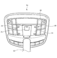
- FIG. 6 is a top view of the main unit 10
- FIG. 7 is a top view of the main unit 10 in a state where the ECU 12 is removed from the main unit 10.
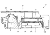
- 8 is a cross-sectional view taken along the line VIII-VIII in FIG. 6, and
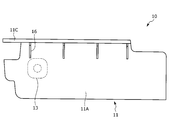
- FIG. 9 is a side view of the main unit 10.
- the main unit 10 mainly holds the ECU 12 (electronic control unit), the vibration motor 13 (an example of a vibration device), and the ECU 12 and the vibration motor 13 that are held inside.
- a member 11 is provided.
- the holding member 11 includes a cover body 11A, an ECU attachment portion 11B (an example of an electronic control portion attachment portion), a holding member attachment portion 11C, and a vibration motor attachment portion 11D.
- the holding member 11 is made of, for example, a resin material.
- the cover body 11 ⁇ / b> A has a substantially U-shaped vertical cross section with the upper part opened, and functions as a casing of the awakening device D.
- a recess 17 that is recessed inward is provided on the lower surface of the cover body 11A.
- a battery end plate 20 is attached to the side wall of the recess 17, and the dry battery 23 is accommodated in the recess 17 in a state where electrodes are arranged in a direction facing the battery end plate 20.
- the battery end plate 20 and the dry battery 23 function as a power source for the ECU 12 and the vibration motor 13.
- the battery cover 21 is a member that engages with the opening on the lower side of the recess 17 and covers the dry battery 23 accommodated in the recess 17. In addition, since the dry battery 23 can be exposed by removing the battery cover 21, the dry battery 23 can be easily replaced.
- an ECU attachment portion 11B On the surface of the concave portion 17 on the seat S1 side, an ECU attachment portion 11B (first attachment portion 11Ba (an example of a first protrusion) and second attachment portion 11Bb (an example of a second protrusion)),
- the ECU support part 19 is formed in a shape protruding to the seat part S1 side.
- the ECU attachment portion 11B and the ECU support portion 19 are members that are integrally formed with the cover main body 11A and support the ECU 12, respectively.
- a screw hole that is screwed into the fixing screw 18 is formed at the center of the ECU attachment portion 11B. Ribs are formed around the ECU attachment portion 11B and the ECU support portion 19, respectively, thereby increasing the strength of the ECU attachment portion 11B and the ECU support portion 19.
- screw insertion holes 12B are formed on one of the four corners of the substrate of the ECU 12, and support portion insertion holes 12C are formed on the other diagonal.
- the screw insertion hole 12B of the ECU 12 and the ECU attachment portion 11B are opposed to each other, and the support portion insertion hole 12C and the ECU support portion 19 are arranged to face each other.
- the ECU 12 can be attached to the holding member 11 by screwing the fixing screw 18 into the screw hole.
- the ECU 12 and the concave portion 17 are separated from each other, and thus, by providing a space between the ECU 12 and the concave portion 17, the heat dissipation of the ECU 12 can be enhanced.
- a through-hole 17A is formed in the central portion of the upper surface of the concave portion 17, and this has a structure for releasing the exhaust heat from the ECU 12, thereby further improving the heat dissipation. it can. Moreover, the attachment state of the inside of the main unit 10 or the dry battery 23 can be confirmed through the through-hole 17A.
- cover body 11A is formed with a plurality of ribs 22 that connect the inner surface of the cover body 11A and the recesses 17, and the ribs 22 can improve the rigidity of the cover body 11A.
- the holding member attaching portion 11C is a portion for attaching the main unit 10 to the seat portion S1, and is formed as a flange extending on both sides of the cover main body 11A.
- a plurality of through holes 15 are formed in the holding member attaching portion 11C, and a tapping screw is passed through each through hole 15 to fix the holding member attaching portion 11C to the lower surface of the seat portion S1. Thereby, the main unit 10 is attached to the lower side of the seat S1.
- the vibration motor attachment portion 11D (an example of a vibration device attachment portion) has an accommodation groove to which the vibration motor 13 is attached and the vibration motor 13 is accommodated.
- the vibration motor 13 corresponds to the vibration device according to the present invention, and is switched between driving and stopping based on a control signal received from the ECU 12.
- the vibration motor 13 may be an unbalanced mass type motor.
- the vibration motor 13 is housed in the housing groove, and a vibration motor cover member 14 (vibration device cover member) is disposed on the top, and the vibration motor cover member 14 covers the upper surface of the vibration motor 13. Is done.
- the vibration motor 13 is sandwiched between the vibration motor mounting portion 11D and the vibration motor cover member 14, the displacement of the vibration motor 13 can be suppressed even in the driving state.
- the upper end portion of the vibration motor cover member 14, that is, the end portion 14A on the seat portion S1 side is closer to the seat portion S1 than the ECU 12.
- the vibration motor cover member 14 contacts the resin plate 40 constituting the lower surface of the seat S1 before the ECU 12. Since it becomes easy to contact, even if it does not provide a protection member in the upper part of ECU12, it becomes possible to protect ECU12 suitably.
- the number of component parts of the main unit 10 can be reduced.
- the ECU 12 is a control device that controls the awakening device D.
- the ECU 12 controls the vibration motor 13 based on the potential difference signal converted into a digital signal indicating the breathing interval detected by the biosensor 30. It has a drive control function.
- the ECU 12 has a wireless communication unit 12A that performs wireless communication together with a CPU, ROM, and RAM for arithmetic control, and the wireless communication unit 12A enables bidirectional communication with the wireless communication terminal 2.
- the ECU 12 may control the operation of the vibration motor 13 based on control signals (a drive signal, a stop signal, etc.) received from the wireless communication terminal 2.
- the signal input to the ECU 12 is a potential difference signal converted into a digital signal by the signal processing circuit, and the output is electric power for driving the vibration motor 13.
- the RAM temporarily stores parameters including signals under calculation control and input / output signals, and functions as a storage unit that stores potential difference signals converted to digital signals and other signals.
- the ROM stores a program executed by the CPU and predetermined parameters.
- the program includes, for example, a setting program for setting a predetermined reference value, and a determination for determining the arousal state based on the reference value.
- a program and a drive program for driving the vibration motor 13 are included.
- the ECU 12 has a function of driving the vibration motor 13 by supplying electric power in accordance with an instruction from the CPU.
- the CPU instruction signal is generated by calculating a signal from the biological sensor 30 (respiration sensor). That is, the CPU determines the awake state of the seated person based on the signal transmitted from the biological sensor 30, and drives the vibration motor 13 when determining the low awake state (that is, not the awake state).
- a signal is output to the vibration motor 13.
- a plurality of ribs 16 are formed on the outer surface of the cover body 11A to connect the cover body 11A and the holding member attachment portion 11C. Thereby, the rigidity of the holding member 11 can be increased. Further, as shown in FIG. 9, a plane in which the surface of at least one rib 16 is extended overlaps with the vibration motor 13. In other words, in the side view of the main unit 10, there is at least one rib 16 that overlaps with the vibration motor 13 in the front-rear direction. With this configuration, vibration from the vibration motor 13 can be attached to the holding member. It can be efficiently transmitted to the seat part S1 via the part 11C.
- FIG. 10 is a schematic top view of the seat S ⁇ b> 1 showing the arrangement of the biosensor 30. As shown in FIG. 10, the first modification is different from the above embodiment in that a plurality of biosensors 30 are provided on the seat S ⁇ b> 1 across the column S ⁇ b> 3.
- the biosensor 30 is disposed at a position where the fluctuation of the pressure applied from the seated person is large during the breathing of the seated person, avoiding the position where the load of the seated person is most applied. May be able to suitably detect the body signal. Assuming such a case, when the seated person is seated shallowly on the seat S1 (in front of the seat S1), that is, when the maximum load area is located on the front side of the support column S3, the biosensor If 30 is arrange
- the biosensor 30 If it is arranged in front of S3, a body signal can be detected suitably.
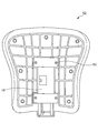
- FIG. 11 shows the rear surface of the backrest S2 to which the main unit 10 is attached.
- the main unit 10 has the holding member attachment portion 11 ⁇ / b> C attached to the back surface portion of the backrest portion S ⁇ b> 2 with a fixing screw 50.
- the backrest portion S2 can be vibrated and vibration can be transmitted to the upper body of the seated person. Can be increased.
- the lower part of the backrest part S2 often faces the waist of the seated person, and the seated person's waist is less likely to leave depending on the posture. For this reason, by attaching the main unit 10 to the lower part of the backrest part S2, it is possible to stably transmit the stimulus to the waist of the seated person, and the awakening effect can be improved.
- the third embodiment is different from the above-described embodiment in that the main unit 10 is attached to the armrest-equipped chair Sa including the armrest S6.
- FIG. 12 is a schematic front view of a chair Sa with an armrest provided with an armrest S6, and FIG. 13 is a schematic bottom view of the chair Sa with an armrest.
- the armrest S6 is attached to both sides of the seat portion S1.
- the armrest mounting portion 60 for mounting the armrest S6 to the lower surface portion of the seat portion S1 is provided on the lower surface portion of the seat portion S1 so as to overlap the main unit 10 in the front-rear direction. It may be attached.
- the fourth embodiment differs from the third embodiment in the mounting position of the armrest mounting portion 60 of the armrest S6. That is, as shown in FIG. 14, the armrest mounting portion 60 for mounting the armrest S6 to the lower surface portion of the seat portion S1 is located at the lower surface portion of the seat portion S1 so as not to overlap the main unit 10 in the front-rear direction. It may be attached to.
- the ECU 12 that controls the vibration motor 13 can be protected by the holding member 11. Further, by integrating the ECU attachment portion 11B for attaching the ECU 12 to the chair body B with the cover body 11A, the number of components of the holding member 11 can be reduced. Thereby, the main unit 10 can be reduced in size and weight.
- the ECU 12 can be protected from an external impact by holding the ECU 12 between the chair body B and the recess 17.
- the awakening device D can be operated by the dry battery 23. Thereby, the installation freedom degree of the chair S can be improved.
- the heat dissipation of the ECU 12 can be improved by separating the ECU 12 attached to the ECU attachment portion 11B and the recess 17 from each other.
- the first mounting portion 11Ba and the second mounting portion 11Bb for mounting the ECU 12 are arranged on the diagonal of the ECU 12, whereby the mounting of the ECU 12 can be stabilized.
- the heat dissipation of the ECU 12 can be enhanced by forming the through hole 17A on the surface of the recess 17 facing the chair body B. Further, the inside of the main unit 10 can be confirmed from the through hole 17A.
- the edge part by the side of the chair main body B of the vibration motor cover member 14 is nearer to the chair main body B side compared with ECU12, Therefore The impact from the chair main body B side is received.
- the ECU 12 can be protected by receiving the vibration motor cover member 14.
- the rigidity of the holding member 11 can be improved by providing the rib 16 which connects 11C of holding member attaching parts 11C of the holding member 11, and 11 A of cover main bodies. .
- the vibration from the vibration motor 13 can be reduced by arranging the flat surface extending the surface of the rib 16 and at least a part of the vibration motor 13 so as to overlap each other. 16 can be efficiently transmitted to the chair body B.
- the ECU 12 includes the wireless communication unit 12A that performs wireless communication with the wireless communication terminal 2, so that the holding member for attaching the ECU 12 having the wireless communication function to the chair main body B. 11 component parts can be reduced.
Landscapes
- Chair Legs, Seat Parts, And Backrests (AREA)
- Measuring And Recording Apparatus For Diagnosis (AREA)
Abstract
La présente invention concerne une chaise qui peut comporter un couvercle de taille réduite protégeant une unité de commande électronique destinée à commander un dispositif vibratoire. Ladite chaise est pourvue d'un corps principal de chaise comportant un siège, et d'un dispositif de réveil pour réveiller la personne assise qui est assise sur le siège. Le dispositif de réveil comprend un capteur qui détecte un signal corporel de la personne assise, un moteur de vibration (13) qui applique un stimulus vibratoire à la personne assise, une ECU (12) qui commande le moteur de vibration (13) en fonction du signal corporel détecté par le capteur, et un élément de maintien (11) qui maintient l'ECU (12). L'élément de maintien (11) comprend un corps principal de couvercle (11A) qui recouvre l'ECU (12), une unité de fixation d'ECU qui est formée d'une seule pièce avec le corps principal de couvercle (11A) et à laquelle est fixée l'ECU (12), et une partie de fixation d'élément de maintien (11C) destinée à fixer l'élément de maintien (11) au corps principal de chaise.
Applications Claiming Priority (4)
| Application Number | Priority Date | Filing Date | Title |
|---|---|---|---|
| JP2016086470 | 2016-04-22 | ||
| JP2016-086470 | 2016-04-22 | ||
| JP2016225341A JP6799254B2 (ja) | 2016-04-22 | 2016-11-18 | 椅子 |
| JP2016-225341 | 2016-11-18 |
Publications (1)
| Publication Number | Publication Date |
|---|---|
| WO2017183419A1 true WO2017183419A1 (fr) | 2017-10-26 |
Family
ID=60116661
Family Applications (1)
| Application Number | Title | Priority Date | Filing Date |
|---|---|---|---|
| PCT/JP2017/013464 Ceased WO2017183419A1 (fr) | 2016-04-22 | 2017-03-30 | Chaise |
Country Status (1)
| Country | Link |
|---|---|
| WO (1) | WO2017183419A1 (fr) |
Citations (5)
| Publication number | Priority date | Publication date | Assignee | Title |
|---|---|---|---|---|
| JPS61136688U (fr) * | 1985-02-13 | 1986-08-25 | ||
| JPH028082U (fr) * | 1988-06-27 | 1990-01-18 | ||
| JPH07322938A (ja) * | 1994-06-01 | 1995-12-12 | Brother Ind Ltd | 振動椅子システム |
| JP2012084452A (ja) * | 2010-10-13 | 2012-04-26 | Yutaka Nagano | ねじ形電池 |
| WO2015099164A1 (fr) * | 2013-12-27 | 2015-07-02 | テイ・エス テック株式会社 | Siège doté d'un dispositif de maintien de l'état de veille |
-
2017
- 2017-03-30 WO PCT/JP2017/013464 patent/WO2017183419A1/fr not_active Ceased
Patent Citations (5)
| Publication number | Priority date | Publication date | Assignee | Title |
|---|---|---|---|---|
| JPS61136688U (fr) * | 1985-02-13 | 1986-08-25 | ||
| JPH028082U (fr) * | 1988-06-27 | 1990-01-18 | ||
| JPH07322938A (ja) * | 1994-06-01 | 1995-12-12 | Brother Ind Ltd | 振動椅子システム |
| JP2012084452A (ja) * | 2010-10-13 | 2012-04-26 | Yutaka Nagano | ねじ形電池 |
| WO2015099164A1 (fr) * | 2013-12-27 | 2015-07-02 | テイ・エス テック株式会社 | Siège doté d'un dispositif de maintien de l'état de veille |
Similar Documents
| Publication | Publication Date | Title |
|---|---|---|
| JP2021035600A (ja) | 椅子 | |
| US12240366B2 (en) | Chair | |
| JP6963191B2 (ja) | 椅子 | |
| JP6565281B2 (ja) | 椅子 | |
| JP7104349B2 (ja) | 椅子 | |
| JP2014231256A (ja) | 乗物用シート | |
| JP5730795B2 (ja) | 車両用シート及び車両用シート装置 | |
| US11896396B2 (en) | Sensor-equipped seat | |
| WO2018092430A1 (fr) | Dispositif de siège | |
| JP2016185256A (ja) | 椅子 | |
| JP6212067B2 (ja) | 椅子 | |
| JP6565282B2 (ja) | 椅子 | |
| JP2016193039A (ja) | 椅子 | |
| JP2013154850A (ja) | 車両用シート | |
| JP5761039B2 (ja) | 車両用シート | |
| JP7089206B2 (ja) | 椅子 | |
| JP6795772B2 (ja) | 椅子 | |
| JP2009046001A (ja) | アシストグリップおよびその取り付け構造 | |
| JP6620414B2 (ja) | 椅子 | |
| CN218923142U (zh) | 按摩背带 | |
| JP2020006183A (ja) | 椅子 | |
| JP4553887B2 (ja) | 着座センサ付き座席 | |
| JP2021129645A (ja) | センサユニット | |
| JP2014231252A (ja) | 乗物用シート | |
| EP3919361A1 (fr) | Véhicule somatosensoriel à interaction homme-machine et corps de véhicule, capot supérieur et structure de support associés |
Legal Events
| Date | Code | Title | Description |
|---|---|---|---|
| NENP | Non-entry into the national phase |
Ref country code: DE |
|
| 121 | Ep: the epo has been informed by wipo that ep was designated in this application |
Ref document number: 17785761 Country of ref document: EP Kind code of ref document: A1 |
|
| 122 | Ep: pct application non-entry in european phase |
Ref document number: 17785761 Country of ref document: EP Kind code of ref document: A1 |