WO2017187615A1 - Gaine pour manipulateur flexible - Google Patents
Gaine pour manipulateur flexible Download PDFInfo
- Publication number
- WO2017187615A1 WO2017187615A1 PCT/JP2016/063428 JP2016063428W WO2017187615A1 WO 2017187615 A1 WO2017187615 A1 WO 2017187615A1 JP 2016063428 W JP2016063428 W JP 2016063428W WO 2017187615 A1 WO2017187615 A1 WO 2017187615A1
- Authority
- WO
- WIPO (PCT)
- Prior art keywords
- tube
- sheath
- protrusion
- inner tube
- lumen
- Prior art date
- Legal status (The legal status is an assumption and is not a legal conclusion. Google has not performed a legal analysis and makes no representation as to the accuracy of the status listed.)
- Ceased
Links
Images


Classifications
-
- B—PERFORMING OPERATIONS; TRANSPORTING
- B25—HAND TOOLS; PORTABLE POWER-DRIVEN TOOLS; MANIPULATORS
- B25J—MANIPULATORS; CHAMBERS PROVIDED WITH MANIPULATION DEVICES
- B25J18/00—Arms
- B25J18/06—Arms flexible
Definitions
- the present invention relates to a sheath for a flexible manipulator.
- a manufactured multi-lumen tube is known (for example, see Patent Document 1).
- a wire for driving a movable portion provided at the distal end of the insertion portion is disposed through each lumen of the multi-lumen tube.
- the present invention has been made in view of the above-described circumstances, and can control the manipulator with high accuracy by suppressing fluctuations in the path length of the wire even when the tension applied to the wire penetrating the lumen is increased.
- An object of the present invention is to provide a sheath for a flexible manipulator.
- a flexible inner tube having a lumen that penetrates a wire along a longitudinal direction, and an outer peripheral surface of the inner tube are disposed so as to be more compressive than the inner tube.
- a plurality of protrusions that are provided on the outer peripheral surface of the inner tube with a radially outer tip closely attached to the inner surface of the outer tube, spaced apart in the circumferential direction.
- the wire when the movable portion of the manipulator provided at the distal end is driven by applying tension to the proximal end of the wire penetrating into the lumen, the wire is flexible due to friction between the wire and the inner surface of the lumen.
- the inner tube is likely to be deformed, but the inner tube is supported by the outer tube with higher compressive strength by closely attaching the protrusion provided on the outer peripheral surface to the inner surface of the outer tube. Deformation is avoided. As a result, even when the wire is pulled, fluctuations in the wire path length are suppressed, and the manipulator can be controlled with high accuracy.
- protrusion may consist of the protruding item
- the protrusion may extend continuously over the entire length of the inner tube.
- protrusion may extend intermittently over the full length of the said inner side tube.
- tip of the said protrusion may have the cross-sectional shape which consists of a convex curved surface.
- protrusion may have a cross-sectional shape extended incline with respect to radial direction from the outer peripheral surface of the said inner side tube.
- the protrusion that contacts the inner surface of the outer tube receives a force inward in the radial direction
- the cavity disposed radially inward of the protrusion is compressed, and the radial position of the protrusion is reduced in diameter. Displace inward direction.
- the inner tube is softly supported on the inner surface of the outer tube, and it is possible to improve the ease of inserting the inner tube into the outer tube and the ease of bending of the sheath.
- protrusion may be provided in the helical form twisted around a longitudinal axis.
- the inner tube includes a plurality of the lumens, each of the lumens is formed in a spiral shape that twists around the longitudinal axis and does not intersect with each other, and the protrusion has a center line of the inner tube. It may be arranged on the opposite side to each of the lumens. In this way, tension is applied to the wire, so that a force that deforms the lumen so as to approach a straight line acts on the spiral lumen that penetrates the wire from the wire.
- the force is effectively supported by the protrusion located on the opposite side of the lumen, and the movement of the inner tube within the outer tube can be prevented, and the variation in the path length can be more reliably prevented.
- the said outer side tube may be a coil tube, and the helical pitch of the said protrusion may be larger than the pitch of the said coil tube.
- the manipulator can be controlled with high accuracy by suppressing the fluctuation of the wire path length.
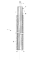
- FIG. 1 It is a whole lineblock diagram showing a flexible manipulator provided with a sheath for flexible manipulators concerning one embodiment of the present invention.
- FIG. 2 It is a cross-sectional view showing a second modification of the inner tube of FIG.
- the soft manipulator 100 is provided with a sheath 1 for a soft manipulator according to this embodiment, a manipulator 2 provided at the distal end of the sheath 1 for soft manipulator, and a proximal end of the manipulator 2.
- a drive unit 3 that generates power for operating the manipulator 2 and a wire 4 that transmits the power generated in the drive unit 3 to the manipulator 2 are provided.
- the manipulator 2 includes a movable part 5 having one or more joints, and an end effector 6 supported at the tip of the movable part 5.
- the drive unit 3 includes, for example, a motor (not shown) and a pulley 7 that transmits the power of the motor to the wire 4.
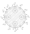
- the flexible manipulator sheath 1 includes a resin-made multi-lumen tube (inner tube) 9 including a plurality of lumens 8 penetrating in the longitudinal direction, and the multi-lumen tube 9.
- a coil tube (outer tube) 10 penetrating inward is provided.
- a wire 4 can be passed through each lumen 8 of the multi-lumen tube 9. Both ends of the wire 4 penetrating the lumen 8 are connected to the manipulator 2 at the distal end of the sheath 1 for the flexible manipulator and the drive unit 3 at the proximal end.
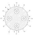
- a plurality of ridges (projections) 11 are provided on the outer peripheral surface of the multi-lumen tube 9 at equal intervals in the circumferential direction as shown in FIG.
- the ridges 11 are integrally formed as a part of the multi-lumen tube 9 with a resin constituting the multi-lumen tube 9 so that the outer peripheral surface of the multi-lumen tube 9 is raised radially outward.
- the multi-lumen tube 9 is manufactured by resin extrusion, and the lumen 8 and the ridges 11 are formed straight along the longitudinal direction.
- the cross-sectional shape of the ridge 11 is, for example, a rectangle.
- the flexible manipulator sheath 1 for the flexible manipulator when tension is applied to the wire 4 by the driving unit 3, the flexible multi-lumen tube 9 is caused by friction between the wire 4 and the inner surface of the lumen 8. Even if elastic deformation is attempted, the radially outer tip of the ridge 11 provided on the outer peripheral surface of the multi-lumen tube 9 is in close contact with the inner surface of the coil tube 10, so that the multi-lumen tube 9 is It is supported by the coil tube 10 via.
- the coil tube 10 has higher compression rigidity than the multi-lumen tube 9, deformation of the multi-lumen tube 9 is suppressed, and fluctuations in the path length of the wire 4 can be prevented.
- the path length of the other wire 4 varies, and the inconvenience of driving the manipulator 2 in an unintended direction is prevented, and the movable part 5 of the manipulator 2 is accurately There is an advantage that it can be controlled well.
- the multi-lumen tube 9 can be more reliably prevented from being deformed. It is difficult to insert the tube 9.
- the outer surface of the multi-lumen tube 9 is partially brought into contact with the inner surface of the coil tube 10 by the protruding ridges 11 spaced in the circumferential direction. Can be greatly reduced, the ease of insertion can be improved, and there is an advantage that assembly is easy.
- the ridges 11 are provided at equal intervals in the circumferential direction, the effect of preventing the variation in the path length of the wire 4 can be generated even when the sheath 1 for the flexible manipulator is bent in any direction. Further, since the ridges 11 are provided over the entire length of the multi-lumen tube 9 in the longitudinal direction, the effect of preventing the fluctuation of the path length of the wire 4 can be made uniform regardless of the position in the longitudinal direction of the sheath 1 for the flexible manipulator Can be generated.
- the dimension may be arbitrary.
- the width dimension of each convex strip 11 may be larger than FIG.
- the cross-sectional shape of the ridge 11 is not limited to a rectangle, and as shown in FIG. 5, a shape having a convex curved surface at the tip, for example, a semicircular cross-section may be adopted.
- the multi-lumen tube 9 extends from the outer peripheral surface of the multi-lumen tube 9 while being inclined with respect to the radial direction, and falls down along the outer peripheral surface of the multi-lumen tube 9 when inserted into the coil tube 10.
- the ridge 11 having a cross-sectional shape that is elastically deformed may be employed.
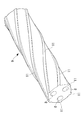
- line 11 was provided continuously over the full length of the longitudinal direction of the multi-lumen tube 9, it is not limited to this, It interrupts in a longitudinal direction It may be provided. Further, the ridges 11 may be formed in a spiral shape that rotates in the circumferential direction along the longitudinal direction of the multi-lumen tube 9. Thereby, the insertion ease at the time of inserting the multi-lumen tube 9 in the coil tube 10 can be improved.
- the pitch of the spiral ridges 11 is preferably different from the pitch of the coil tube 10. Thereby, it can prevent that the protruding item
- the multi-lumen tube 9 having four lumens 8 is illustrated as the inner tube, but instead, a single lumen tube having a single lumen 8 or an arbitrary number of two or more A multi-lumen tube having a plurality of lumens may be employed.
- the multi-lumen tube 9 in which the lumen 8 extends straight along the longitudinal direction is illustrated, but instead, a twisted multi-lumen in which the lumen 8 is twisted in one direction around the central axis.
- a tube may be employed.
- the ridges 11 may be formed straight along the longitudinal direction of the multi-lumen tube 9, but when manufactured by twisting after extrusion, the pitch is the same as the twist pitch of the lumen 8. It may be twisted.
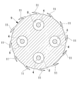
- each protrusion 11 is formed on the side opposite to the lumen 8 across the center line of the multi-lumen tube 9 as shown in FIG. It is possible to prevent the multi-lumen tube 9 from being deformed by receiving a force acting on the lumen 8 by the tension of the wire 4 so that the lumen 8 is straightened. As shown in FIG. 8, the number of ridges 11 may not be the same as the number of lumens 8.
- a hollow portion 12 may be provided at the base of each ridge 11, and the ridge 11 may be easily displaced in the radial direction. Thereby, the ease of insertion of the multi-lumen tube 9 into the coil tube 10 can be improved.
- the cavity 12 may be provided continuously over the entire length in the longitudinal direction, or may be provided intermittently.
Landscapes
- Engineering & Computer Science (AREA)
- Robotics (AREA)
- Mechanical Engineering (AREA)
- Media Introduction/Drainage Providing Device (AREA)
Abstract
Afin de supprimer la variation de la longueur du trajet du fil pour commander avec précision un manipulateur y compris lorsque la force de traction sur le fil passant à travers une lumière augmente, l'invention propose une gaine de manipulateur flexible (1) qui comprend un tube intérieur flexible (9) présentant une lumière (8) à travers laquelle un fil (4) passe dans le sens longitudinal, et un tube extérieur flexible (10) qui est disposé de façon à recouvrir la surface périphérique extérieure du tube intérieur (9) et dont la rigidité à la compression est supérieure à celle du tube intérieur (9) ; plusieurs parties saillantes (11), espacées dans la direction circonférentielle, étant situées sur la surface périphérique extérieure du tube intérieur (9), les extrémités radialement extérieures desdites parties saillantes étant mises en contact étroit avec la surface intérieure du tube extérieur (11).
Priority Applications (1)
| Application Number | Priority Date | Filing Date | Title |
|---|---|---|---|
| PCT/JP2016/063428 WO2017187615A1 (fr) | 2016-04-28 | 2016-04-28 | Gaine pour manipulateur flexible |
Applications Claiming Priority (1)
| Application Number | Priority Date | Filing Date | Title |
|---|---|---|---|
| PCT/JP2016/063428 WO2017187615A1 (fr) | 2016-04-28 | 2016-04-28 | Gaine pour manipulateur flexible |
Publications (1)
| Publication Number | Publication Date |
|---|---|
| WO2017187615A1 true WO2017187615A1 (fr) | 2017-11-02 |
Family
ID=60161442
Family Applications (1)
| Application Number | Title | Priority Date | Filing Date |
|---|---|---|---|
| PCT/JP2016/063428 Ceased WO2017187615A1 (fr) | 2016-04-28 | 2016-04-28 | Gaine pour manipulateur flexible |
Country Status (1)
| Country | Link |
|---|---|
| WO (1) | WO2017187615A1 (fr) |
Cited By (2)
| Publication number | Priority date | Publication date | Assignee | Title |
|---|---|---|---|---|
| CN109048856A (zh) * | 2018-08-03 | 2018-12-21 | 江苏大学 | 一种刚度独立可控的软体机器人致动器 |
| CN110370313A (zh) * | 2019-07-18 | 2019-10-25 | 哈工大(威海)创新创业园有限责任公司 | 一种柔性臂以及线珠耦合双向驱动的柔性机械臂 |
Citations (3)
| Publication number | Priority date | Publication date | Assignee | Title |
|---|---|---|---|---|
| JP2009178568A (ja) * | 2001-06-07 | 2009-08-13 | Olympus Corp | 内視鏡用縫合器 |
| JP2009530051A (ja) * | 2006-03-23 | 2009-08-27 | ボストン サイエンティフィック リミテッド | 医療デバイスおよびシステム |
| WO2014004300A1 (fr) * | 2012-06-28 | 2014-01-03 | Ethicon Endo-Surgery, Inc. | Système d'instrument chirurgical comprenant des effecteurs d'extrémité remplaçables |
-
2016
- 2016-04-28 WO PCT/JP2016/063428 patent/WO2017187615A1/fr not_active Ceased
Patent Citations (3)
| Publication number | Priority date | Publication date | Assignee | Title |
|---|---|---|---|---|
| JP2009178568A (ja) * | 2001-06-07 | 2009-08-13 | Olympus Corp | 内視鏡用縫合器 |
| JP2009530051A (ja) * | 2006-03-23 | 2009-08-27 | ボストン サイエンティフィック リミテッド | 医療デバイスおよびシステム |
| WO2014004300A1 (fr) * | 2012-06-28 | 2014-01-03 | Ethicon Endo-Surgery, Inc. | Système d'instrument chirurgical comprenant des effecteurs d'extrémité remplaçables |
Cited By (3)
| Publication number | Priority date | Publication date | Assignee | Title |
|---|---|---|---|---|
| CN109048856A (zh) * | 2018-08-03 | 2018-12-21 | 江苏大学 | 一种刚度独立可控的软体机器人致动器 |
| CN110370313A (zh) * | 2019-07-18 | 2019-10-25 | 哈工大(威海)创新创业园有限责任公司 | 一种柔性臂以及线珠耦合双向驱动的柔性机械臂 |
| CN110370313B (zh) * | 2019-07-18 | 2022-04-22 | 哈工大(威海)创新创业园有限责任公司 | 一种柔性臂以及线珠耦合双向驱动的柔性机械臂 |
Similar Documents
| Publication | Publication Date | Title |
|---|---|---|
| US10864004B2 (en) | Flexible-manipulator sheath and manipulator | |
| US5520222A (en) | Bending device | |
| CN105828738B (zh) | 柔性机械手用引导部件和柔性机械手 | |
| US9526862B2 (en) | Medical tube and flexibility-variable mechanism with the same | |
| JP2019528965A (ja) | 作動可能な作業端部を有する回転式の捩り可能な血管内装置 | |
| US20240269441A1 (en) | Balloon For Catheter And Balloon Catheter | |
| CA3131784A1 (fr) | Endoscope | |
| WO2017187615A1 (fr) | Gaine pour manipulateur flexible | |
| KR20140020383A (ko) | 가변 강성 구조체 | |
| WO2016185817A1 (fr) | Tube flexible et endoscope utilisant le tube flexible | |
| CN212521715U (zh) | 一种用于内窥镜的线引导部件及一种内窥镜 | |
| TWI792642B (zh) | 彎曲結構體 | |
| CN108013861A (zh) | 一种柔性管及其组合 | |
| JP4360934B2 (ja) | 内視鏡の湾曲部 | |
| CN117715734A (zh) | 弯曲结构体 | |
| JP6869350B2 (ja) | 内視鏡用可撓管及び内視鏡 | |
| WO2016203820A1 (fr) | Tube souple et endoscope utilisant un tube souple | |
| JPS5912468Y2 (ja) | ケ−ブル又はパイプの誘導用撓曲筒 | |
| JP2000331541A (ja) | 伸縮自在コード | |
| JP4448362B2 (ja) | 内視鏡の湾曲装置 | |
| JPS6324886Y2 (fr) | ||
| JP2003190290A5 (fr) | ||
| WO2018216109A1 (fr) | Manipulateur souple | |
| JP2008000310A (ja) | 内視鏡用処置具 | |
| JP6149256B2 (ja) | コントロールケーブル |
Legal Events
| Date | Code | Title | Description |
|---|---|---|---|
| NENP | Non-entry into the national phase |
Ref country code: DE |
|
| 121 | Ep: the epo has been informed by wipo that ep was designated in this application |
Ref document number: 16900485 Country of ref document: EP Kind code of ref document: A1 |
|
| 122 | Ep: pct application non-entry in european phase |
Ref document number: 16900485 Country of ref document: EP Kind code of ref document: A1 |
|
| NENP | Non-entry into the national phase |
Ref country code: JP |