WO2017187683A1 - Sac dans une boîte - Google Patents
Sac dans une boîte Download PDFInfo
- Publication number
- WO2017187683A1 WO2017187683A1 PCT/JP2017/002797 JP2017002797W WO2017187683A1 WO 2017187683 A1 WO2017187683 A1 WO 2017187683A1 JP 2017002797 W JP2017002797 W JP 2017002797W WO 2017187683 A1 WO2017187683 A1 WO 2017187683A1
- Authority
- WO
- WIPO (PCT)
- Prior art keywords
- suspension container
- insertion hole
- suspension
- storage box
- container
- Prior art date
- Legal status (The legal status is an assumption and is not a legal conclusion. Google has not performed a legal analysis and makes no representation as to the accuracy of the status listed.)
- Ceased
Links
Images

























Classifications
-
- B—PERFORMING OPERATIONS; TRANSPORTING
- B65—CONVEYING; PACKING; STORING; HANDLING THIN OR FILAMENTARY MATERIAL
- B65D—CONTAINERS FOR STORAGE OR TRANSPORT OF ARTICLES OR MATERIALS, e.g. BAGS, BARRELS, BOTTLES, BOXES, CANS, CARTONS, CRATES, DRUMS, JARS, TANKS, HOPPERS, FORWARDING CONTAINERS; ACCESSORIES, CLOSURES, OR FITTINGS THEREFOR; PACKAGING ELEMENTS; PACKAGES
- B65D77/00—Packages formed by enclosing articles or materials in preformed containers, e.g. boxes, cartons, sacks or bags
- B65D77/04—Articles or materials enclosed in two or more containers disposed one within another
- B65D77/06—Liquids or semi-liquids or other materials or articles enclosed in flexible containers disposed within rigid containers
- B65D77/062—Flexible containers disposed within polygonal containers formed by folding a carton blank
- B65D77/065—Spouts, pouring necks or discharging tubes fixed to or integral with the flexible container
- B65D77/067—Spouts, pouring necks or discharging tubes fixed to or integral with the flexible container combined with a valve, a tap or a piercer
-
- B—PERFORMING OPERATIONS; TRANSPORTING
- B31—MAKING ARTICLES OF PAPER, CARDBOARD OR MATERIAL WORKED IN A MANNER ANALOGOUS TO PAPER; WORKING PAPER, CARDBOARD OR MATERIAL WORKED IN A MANNER ANALOGOUS TO PAPER
- B31B—MAKING CONTAINERS OF PAPER, CARDBOARD OR MATERIAL WORKED IN A MANNER ANALOGOUS TO PAPER
- B31B50/00—Making rigid or semi-rigid containers, e.g. boxes or cartons
- B31B50/26—Folding sheets, blanks or webs
-
- B—PERFORMING OPERATIONS; TRANSPORTING
- B65—CONVEYING; PACKING; STORING; HANDLING THIN OR FILAMENTARY MATERIAL
- B65D—CONTAINERS FOR STORAGE OR TRANSPORT OF ARTICLES OR MATERIALS, e.g. BAGS, BARRELS, BOTTLES, BOXES, CANS, CARTONS, CRATES, DRUMS, JARS, TANKS, HOPPERS, FORWARDING CONTAINERS; ACCESSORIES, CLOSURES, OR FITTINGS THEREFOR; PACKAGING ELEMENTS; PACKAGES
- B65D5/00—Rigid or semi-rigid containers of polygonal cross-section, e.g. boxes, cartons or trays, formed by folding or erecting one or more blanks made of paper
- B65D5/42—Details of containers or of foldable or erectable container blanks
- B65D5/44—Integral, inserted or attached portions forming internal or external fittings
- B65D5/50—Internal supporting or protecting elements for contents
- B65D5/5028—Elements formed separately from the container body
- B65D5/5035—Paper elements
-
- B—PERFORMING OPERATIONS; TRANSPORTING
- B65—CONVEYING; PACKING; STORING; HANDLING THIN OR FILAMENTARY MATERIAL
- B65D—CONTAINERS FOR STORAGE OR TRANSPORT OF ARTICLES OR MATERIALS, e.g. BAGS, BARRELS, BOTTLES, BOXES, CANS, CARTONS, CRATES, DRUMS, JARS, TANKS, HOPPERS, FORWARDING CONTAINERS; ACCESSORIES, CLOSURES, OR FITTINGS THEREFOR; PACKAGING ELEMENTS; PACKAGES
- B65D77/00—Packages formed by enclosing articles or materials in preformed containers, e.g. boxes, cartons, sacks or bags
- B65D77/04—Articles or materials enclosed in two or more containers disposed one within another
- B65D77/06—Liquids or semi-liquids or other materials or articles enclosed in flexible containers disposed within rigid containers
-
- B—PERFORMING OPERATIONS; TRANSPORTING
- B65—CONVEYING; PACKING; STORING; HANDLING THIN OR FILAMENTARY MATERIAL
- B65D—CONTAINERS FOR STORAGE OR TRANSPORT OF ARTICLES OR MATERIALS, e.g. BAGS, BARRELS, BOTTLES, BOXES, CANS, CARTONS, CRATES, DRUMS, JARS, TANKS, HOPPERS, FORWARDING CONTAINERS; ACCESSORIES, CLOSURES, OR FITTINGS THEREFOR; PACKAGING ELEMENTS; PACKAGES
- B65D83/00—Containers or packages with special means for dispensing contents
-
- B—PERFORMING OPERATIONS; TRANSPORTING
- B65—CONVEYING; PACKING; STORING; HANDLING THIN OR FILAMENTARY MATERIAL
- B65D—CONTAINERS FOR STORAGE OR TRANSPORT OF ARTICLES OR MATERIALS, e.g. BAGS, BARRELS, BOTTLES, BOXES, CANS, CARTONS, CRATES, DRUMS, JARS, TANKS, HOPPERS, FORWARDING CONTAINERS; ACCESSORIES, CLOSURES, OR FITTINGS THEREFOR; PACKAGING ELEMENTS; PACKAGES
- B65D2231/00—Means for facilitating the complete expelling of the contents
Definitions
- the present invention comprises a storage box provided with an insertion hole for a pouring nozzle at the lower end of the side wall, and a suspension container made of a film material stored in a suspended state in the storage box, and the pouring nozzle attached to the lower end of the suspension container
- An object of the present invention is to provide a bag-in-box in which an opening / closing mechanism is attached to the end of the bag through the insertion hole.
- a bag-in-box is such an environmentally friendly packaging container, which is composed of a plastic interior container and an exterior container mainly composed of a cardboard case. It is a container.
- the present invention relates to a so-called “film type” interior container, and “film type” is generally a film bag formed by thermally welding a 2 ⁇ 3 layer film by a heat seal method or an impulse seal method. It is a thing. And the spout shape
- Corrugated cardboard cases are generally used as outer containers, and the material configuration and form are selected from the required qualities such as capacity, transportation conditions, and post-line suitability.
- Patent Document 6 An example in which the inner container is suspended from the upper part of the outer container JP-A-6-171668 (see Patent Document 7) 3) An example in which a reinforcing material is attached to the side wall of the outer container JP-A-7-315436 (see Patent Document 8)
- An opening / closing stopper having a built-in, a dispensing nozzle attached to the lower end, and a suspension container made of a film material that can be stored in a suspended state in the storage box, the dispensing nozzle attached to the lower end of the suspension container, A bag-in-box that is pulled out from the insertion hole and has an automatic shut-off valve attached to its end, and on both sides of the bottom of the storage box, the suspension container is directed from the outside to the inside above the insertion hole.
- An inclined base is provided, and a V-shaped guide groove that guides the lower end of the suspension container toward the end of the pouring nozzle is formed at an intermediate position thereof.
- the upper part of the suspension container Suspension means for suspending holding the closing plug provided proposed bag-in-box that is provided.
- an object of the present invention is to provide a bag-in-box that can achieve a significant cost reduction.
- the bag-in-box of the present invention includes a storage box provided with an insertion hole for the pouring nozzle opening / closing mechanism at the lower end of the side wall, and a suspension container made of a film material stored in the storage box in a suspended state.
- the bottom of the storage box is provided with a base that tilts and holds toward the insertion hole, and the base plate constituting the base is a horizontal plate that is folded downward with side plates provided halfway on both sides of the base plate.
- the upper part of the storage box is provided with a suspension means for hanging and holding an open / close stopper provided on the upper part of the suspension container, When filling the liquid contents, the open / close stopper of the suspension container is opened, When pouring the liquid contents, the open / close stopper provided on the upper part of the suspension container is suspended and held by the suspension means and the opening / closing stopper is closed, and is attached to the lower end of the suspension container in the storage box.
- the nozzle opening / closing mechanism is drawn out from the insertion hole, and is characterized in that it can be dispensed by opening the dispensing nozzle opening / closing mechanism.
- the open / close stopper provided on the upper part of the suspension container has a built-in check valve, and the suspension container is opened to fill the suspension container with the liquid content, After closing the stopper and discharging the air in the suspension container from the check valve, the suspension container is filled with only the liquid contents, and the suspension container is fitted into the storage box, and the dispensing nozzle at the lower end of the suspension container is opened and closed. While pulling out the mechanism from the insertion hole, The open / close stopper provided on the upper part of the suspension container is also suspended and held by the suspension means.
- the bag-in-box of the present invention comprises a storage box provided with an insertion hole for the pouring nozzle opening / closing mechanism at the lower end of the side wall, and a suspension container made of a film material stored in a suspended state in the storage box, the lower end of the suspension container A bag-in-box that is used by pulling out the extraction nozzle opening / closing mechanism attached to the insertion hole,
- the bottom of the storage box is provided with a base for holding the suspended container above the insertion hole, and the base has a downward slope toward the insertion hole of the dispensing nozzle opening / closing mechanism. Is also a feature.
- the storage box provided with the insertion hole of the pouring nozzle opening / closing mechanism at the lower end of the side wall is arranged on the product display shelf by making the width of the insertion hole forming side wall surface narrower than the width of other orthogonal side wall surfaces. It is also characterized in that it can be displayed side by side.
- a storage box provided with an insertion hole for the pouring nozzle opening / closing mechanism at the lower end of the side wall and a suspension container made of a film material stored in a suspended state in the storage box are attached to the lower end of the suspension container. Since the dispensing nozzle opening / closing mechanism is used by being pulled out from the insertion hole, the liquid content remaining in the “film type” interior container in the bag-in-box can be reliably discharged to the end.
- a bag-in-box can be provided.
- the check valve can discharge the liquid content in the suspension container so that no air remains, and the liquid content is prevented from being oxidized and the liquid content is kept fresh.
- a base is provided at the bottom of the storage box, and since the base has a downward slope toward the insertion hole of the pouring nozzle opening / closing mechanism, it is surely discharged to the end. It is possible to provide a bag-in-box that makes it possible.
- the storage box can be displayed side by side on the merchandise display shelf by narrowing the width of the storage box, so that the storage box can be displayed not only in department stores but also in supermarkets and convenience stores.
- a very low cost bag-in-box can be provided by the sound to be standardized.
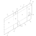
- FIG. It is an expanded view which shows the example of the storage box which comprises the bag in box which concerns on this invention.
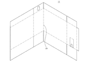
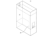
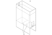
- FIG. It is the perspective view of the state which showed the assembly process and was bent in the L-shape in the center part. It is a perspective view which shows the state which bent one inward side plate further inward. It is a perspective view which shows the state which bent the other wide side board further inward. It is a perspective view which shows the state which turned up the thin bottom board of both sides so that it might become inward horizontal. It is a perspective view which shows the state which turned up the wide bottom board of both sides so that it might become inward horizontal, and it was bottomed. It is a top view which shows the base plate which comprises a base.
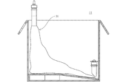
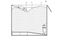
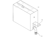
- FIG. 1 It is a perspective view which shows the state which pulled out the extraction nozzle opening / closing mechanism from the one thin side board lower part of the storage box. It is the schematic sectional drawing. It is a schematic sectional drawing of the state which discharge
- (A) is a perspective view which shows each part of the decomposition
- (b) is a perspective view which shows the state cut
- (A) is a perspective view which shows each part of the decomposition
- (b) is a perspective view which shows the state cut
- FIG. 1 It is a perspective view which shows the state cut
- (A) is a disassembled perspective view which shows the cylindrical housing and upper operation lever body which comprise the extraction nozzle opening and closing mechanism
- (b) is a perspective view which shows the state cut
- (A) is a disassembled perspective view which shows a closing stopper and a cylindrical slide body
- (b) is a perspective view which shows the state cut
- (A) is a disassembled perspective view which shows a cover body
- (b) is a perspective view which shows the state cut
- (A) is a disassembled perspective view which shows an operation lever
- (b) is a perspective view which shows the state cut
- FIGS. 1 to 35 show the storage box
- FIGS. 36 to 44 show the opening / closing valve of the suspension container
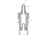
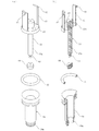
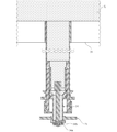
- FIGS. 45 to 58 show the dispensing nozzle opening / closing mechanism used for the suspension container.
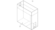
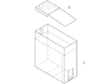
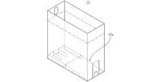
- 1 to 35 show an example of a storage box 11 constituting a bag-in-box according to the present invention, and the storage box 11 further includes a base 12. 1 and 2, the storage box 11 has a side plate portion in which a wide side plate 13 and a narrow side plate 14 having different widths are sequentially connected in pairs, and a width provided above and below each side plate 13, 14.
- the wide bottom plate 15 and the thin bottom plate 16 are different from each other, and the wide top plate 17 and the thin top plate 18 are connected to each other via a crease 19.
- 20 is a connecting piece provided at the end of the side plate portion
- 21 is an insertion hole of a dispensing nozzle opening / closing mechanism provided at the lower end of the thin side plate 14
- 22 is an opening for holding the open / close stopper provided above the suspension container. It is a suspension means consisting of parts.
- FIGS. 8 to 13 show a base plate 12a constituting the base 12.
- FIG. That is, in the base plate 12a shown in FIGS. 8 and 9, the rear end portion of the base plate 12a is turned downward as shown in FIG. 10, and then the rear end portion of the base plate 12a is shown in FIG.
- the support plates 12b on both sides are further folded inward.
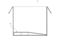
- the base plate 12 has a horizontal portion in which side plates 12c provided halfway on both sides of the base plate 12a are folded downward, and a slope portion 12d continuous therewith, as shown in FIG.
- the base 12 is completed when the slope portion 12d protruding from the position of the side plate 12c of the base plate 12a is folded back obliquely downward.
- the completed base 12 is housed so as to be dropped into the storage box 11 as shown in FIG. 14, and constitutes an inclined bottom portion in the storage box 11 as shown in FIGS.
- FIG. 17 shows an example of a suspension container 31 made of a film material, in which two plastic sheets 31a are joined to each other by means of fusion or the like so as to form a substantially triangular shape.
- An opening / closing stopper 41 is attached to the upper end of one side, and a dispensing nozzle opening / closing mechanism 51 is attached to the lower end of the other side.
- the suspension container 31 made of a film material is stored so as to be dropped into the storage box 11. In that case, the initial suspension container 31 is wrinkled as shown in FIG.
- FIG. 20 shows a state in which the liquid content L is almost completely filled in the suspension container 31.
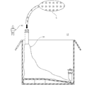
- FIG. 22 shows a state in which the liquid content L is almost completely filled in the suspension container 31.
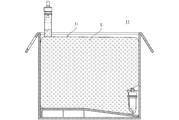
- the suspension container 31 is pressed and discharged so that the air A may be pushed out. Then, after the air A is completely discharged from the upper part of the suspension container 31 as shown in FIG. 23, the cap 42 is assembled to the opening / closing stopper 41 of the suspension container 31 as shown in FIGS.
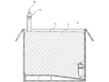
- the opening / closing stopper 41 of the suspension container 31 is assembled to the suspension means 22 composed of a gourd-shaped opening provided on the thin top plate 18 of the storage box 11. 27 and 28, the open / close stopper 41 of the suspension container 31 is folded onto the suspension container 31, and the wide top plate 17 is folded onto the suspension container 31 as shown in FIGS. If it is included, the assembly is complete.
- the dispensing nozzle opening / closing mechanism 51 is pulled out from the insertion hole 21 at the lower end of one narrow side plate 14 of the storage box 11, and the operation lever described later is pulled down. .
- FIG. 33 shows a state in which the discharge of the liquid content L is almost finished.
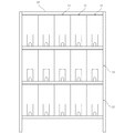
- the bag-in-box of the present invention is narrower than the conventional bag-in-box. Therefore, as shown in FIG. 34, even if they are displayed side by side, the width is not so large, so that the storage boxes 11 can be displayed in multiple stages on the display shelf 81 or the like as shown in FIG.
- FIG. 36 to 44 show an open / close stopper attached to the upper part of the suspension container 31.
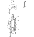
- FIG. First, FIG. 36 and FIG. 37 show parts in an exploded state of the opening / closing stopper 41.
- the holding mechanism 42 for the check valve which is a main part of the opening / closing stopper 41, and the cylindrical shape for storing and holding the holding mechanism 42 are shown.
- a main body 43 and a lid body 44 that is screwed into the upper portion of the cylindrical main body 43 and fixes the holding mechanism 42 to the cylindrical main body 43 are provided.
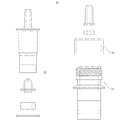
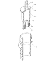
- the check valve holding mechanism 42 will be described with reference to FIGS. 38A and 38B.
- the check valve holding mechanism 42 is detached from the upper end of the cylindrical holding portion 42a upward via a flange portion 42b.
- An air nozzle 42c is formed.
- a check valve 42e provided with a cut in the upper end arch portion is engaged and held at the step 42d provided at the lower portion of the inner wall of the cylindrical holding portion 42a.
- 42f is a cylindrical elastic body that prevents the check valve 42e from coming off the inner wall of the cylindrical holding portion 42a
- 42g is a packing that is interposed between the flange portion 42b at the upper end of the cylindrical holding portion 42a and the cylindrical main body 43. .
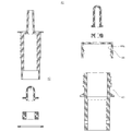
- FIG. 39 (a) and 39 (b) show a cylindrical main body 43, a lid 44, and a cap 45 that house a check valve holding mechanism 42 in the opening / closing plug 41.
- the cylindrical main body 43 is formed with a plurality of circumferential grooves 43a for reliably welding the suspension container 31 on the outer periphery of the lower portion, and is provided with an external screw 43c via a flange portion 43b.
- the lid body 44 is fixed to the cylindrical main body 43 by screwing an inner screw 44 a into an outer screw 43 c of the cylindrical main body 43.
- 44b is an insertion hole of the deaeration nozzle 42c
- 44c is a packing when the cap 45 is attached.
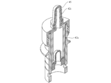
- the cylindrical main body 43 is pushed in from the lower side of the cylindrical holding portion 42a along the outer periphery thereof from the state shown in FIG. At that time, the cylindrical main body 43 is pushed into the flange portion 42b at the upper end of the cylindrical holding portion 42a. At the same time, the packing 42g is interposed between the upper end of the cylindrical main body 43 and the flange portion 42b. Then, after holding the check valve holding mechanism 42 in the cylindrical main body 43 as shown in FIG. 42 from the state shown in FIG. 41, a lid 44 is attached, and as shown in FIGS. The cap 45 is assembled to the deaeration nozzle 42 c of the valve holding mechanism 42.
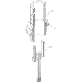
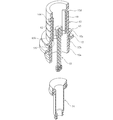
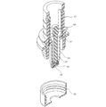
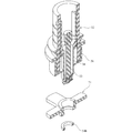
- FIGS. 45 to 58 show the dispensing nozzle opening / closing mechanism 51 attached to the lower end of the suspension container 31.
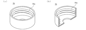
- FIG. As shown in FIGS. 45 and 46, the cylindrical housing 52 has circumferential grooves 52e formed at predetermined intervals along the length direction on the outer periphery thereof, so that the cylindrical housing 52 is more firmly joined to the suspension container 31 by welding. Used for An outer screw 52 a is formed at the lower end of the cylindrical housing 52, and the lid 56 is attached by an inner screw portion 56 a provided on the lid 56. On the outer periphery of the cylindrical housing 52, a ring-shaped flange portion 52c is formed at a predetermined interval from the ring-shaped frame portion 52b at the end of the external screw 52a.
- 52 d and 52 d are a plurality of engagement holes provided in the inner wall of the cylindrical housing 52.
- a stopper plug 53 is detachably attached in the cylindrical housing 52.
- the closing plug 53 includes a vertical arm portion 61 provided with a plurality of engaging holes 52d, 52d provided on the inner wall of the cylindrical housing 52 at its upper end.
- An engaging arm 63a composed of a lateral arm portion 63 having its lower ends connected at a predetermined interval, a closing plug body 53a fixed to the lateral arm portion 63 downward, and an end of the closing plug body 53a.
- a closing packing 64 is attached so as to wrap the periphery of the expansion head 65 provided at the tip of the closing plug 53.
- a cylindrical slide body 54 is attached to the cylindrical housing 52 so as to wrap at least the lower part of the closing plug 53 along the inner peripheral surface of the lower end thereof. As shown in FIG. 48, the cylindrical slide body 54 is held so as to slide up and down in the cylindrical housing 52 via a slide packing 55. 49 is attached to the outer screw 52a of the cylindrical housing 52 via the inner screw portion 56a. And as shown in FIG. 54, the said closing plug 53 makes the lower end protrude from the cover body 56 attached to the said cylindrical housing 52. As shown in FIG.
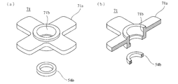
- an operation lever 71 having a petal-like engagement portion 71a extended in the horizontal direction is attached.
- the operation lever 71 has a mounting hole 71b that is inserted through and attached to the lower end of the cylindrical slide body 54 at the center thereof.
- the mounting lever 71b is inserted through the lower end of the cylindrical slide body 54, and the cylinder A retaining packing 54b is attached to a circumferential groove 54a provided at the lower end of the cylindrical slide body 54 and can be prevented from coming off from the cylindrical slide body 54.
- the cylindrical housing 52 is provided with a predetermined space between the lid 56 attached to the external screw 52a and the external screw 52a.
- An upper operation lever body 72 is interposed between the flange 52b projecting from the outer periphery.
- the upper operation lever body 72 can be mounted at the position by expanding the diameter by a cut line (not shown) or the like.
- the upper operation lever body 72 sandwiches the operation lever 71 of the cylindrical housing 52 with a finger or the like so that the operation lever 71 can be easily returned.
- the closing plug 53 When the parts are assembled, the closing plug 53 is pushed in from the lower side of the cylindrical housing 52 as shown in FIG. 52 from the state shown in FIG. Then, the closing plug 53 engages with a plurality of engaging holes 52d, 52d provided on the inner wall of the cylindrical housing 52, and a protrusion 62 provided outwardly on the upper end of the vertical arm portion 61. At this time, the protruding portion 63b provided on the outer periphery of the lateral arm portion 63 is engaged with the step 52f provided at a predetermined height of the inner wall of the cylindrical housing 52 and is not pushed further.
- the cylindrical slide body 54 is pushed in from the lower side of the cylindrical housing 52 from the state shown in FIG. At that time, the cylindrical slide body 54 is slid upward in the cylindrical housing 52 through the slide packing 55 and pushed into the position of the lateral arm portion 63 of the closing plug 53, and the outside of the closing plug 53 is predetermined. It is held to wrap around at intervals. At the same time, the cylindrical closing portion 66 at the lower end of the cylindrical slide body 54 is engaged with the closing packing 64 of the closing plug 53.
- the cylindrical slide body 54 is limited in the downward sliding position by the lid 56. Is done. Then, from the state shown in FIG. 54, as shown in FIGS. 55 and 56, the operating lever 71 is pushed into the lower end of the cylindrical slide body 54, and is pulled out into the circumferential groove 54a provided at the lower end of the cylindrical slide body 54. If the stopper packing 54 b is attached, the operation lever 71 is securely attached to the cylindrical slide body 54.
- the state in which the dispensing nozzle 73 is opened can be easily held by simply pulling down the operation lever 71 as shown in FIGS.
- the operating lever 71 is pushed up to push the closing lever 66 into engagement with the closing packing 64 of the closing plug 53, so that the closed state can be easily held.
- the liquid content can be controlled to be dispensed by a very simple operation. That is, when the cylindrical slide body 54 is in the upper end position, the closing portion 66 is closed by engaging with the closing packing 64 of the closing plug 53, and the cylindrical slide is operated by the downward operation of the operation lever 71. When the body 54 is in the lower position, the engagement between the closing portion 66 and the closing packing 64 of the closing plug 53 is released, and the cylindrical slide body 54 is opened to be in a dispensing state.
- bag-in-box for example, as a business transport container, various foods (dairy products, seasoning liquids, alcoholic beverages, edible oils, soft drinks, fruits, etc.), chemicals ( It can be used for photographic processing agents, surfactants, metal processing agents, floor waxes, etc.) and toiletries (shampoos, rinses, liquid detergents, etc.).
- the present invention can be used for applications other than the above-mentioned applications and for storing contents of 10 liters or less as well as the mainstream of 18 to 20 liters.
Landscapes
- Engineering & Computer Science (AREA)
- Mechanical Engineering (AREA)
- Packages (AREA)
Abstract
L'invention concerne un sac dans une boîte, qui comprend : une boîte de réception (11), qui, dans une paroi latérale de section inférieure (14) de la boîte de réception, comporte un trou d'insertion (21) destiné à un mécanisme d'ouverture/fermeture de buse d'extraction (51) ; et un récipient de suspension (31) qui comprend un matériau de film et qui est renfermé dans la boîte de réception (11) dans un état suspendu, ledit mécanisme d'ouverture/fermeture de buse d'extraction (51) étant attaché à une extrémité inférieure du récipient de suspension (31) et étant tiré hors du trou d'insertion (21) destiné à être utilisé, une base (12) qui maintient une inclinaison vers le trou d'insertion (21) étant disposée sur une section inférieure de la boîte de réception (11), des moyens de suspension (22) qui maintiennent la suspension d'un bouchon d'ouverture/fermeture (41) étant disposés sur une section supérieure de la boîte de réception (11), ledit bouchon d'ouverture/fermeture (41) étant disposé sur une section supérieure du récipient de suspension (31), le bouchon d'ouverture/fermeture (41) du récipient de suspension (31) étant ouvert pendant le remplissage avec un contenu liquide (L), les moyens de suspension (22) maintenant la suspension du bouchon d'ouverture/fermeture (41) qui est disposé sur la section supérieure du récipient de suspension (31), et le bouchon d'ouverture/fermeture (41) étant fermé pendant l'extraction du contenu liquide (L), et l'extraction étant possible par l'ouverture du mécanisme d'ouverture/fermeture de buse d'extraction (51).
Priority Applications (4)
| Application Number | Priority Date | Filing Date | Title |
|---|---|---|---|
| CN201780026726.4A CN109071089A (zh) | 2016-04-30 | 2017-01-26 | 盒中袋 |
| US16/097,554 US11912487B2 (en) | 2016-04-30 | 2017-01-26 | Bag-in box |
| KR1020187031506A KR20190002497A (ko) | 2016-04-30 | 2017-01-26 | 백-인 박스 |
| EP17788973.0A EP3450348A4 (fr) | 2016-04-30 | 2017-01-26 | Sac dans une boîte |
Applications Claiming Priority (2)
| Application Number | Priority Date | Filing Date | Title |
|---|---|---|---|
| JP2016092188A JP6045011B1 (ja) | 2016-04-30 | 2016-04-30 | バッグインボックス |
| JP2016-092188 | 2016-04-30 |
Publications (1)
| Publication Number | Publication Date |
|---|---|
| WO2017187683A1 true WO2017187683A1 (fr) | 2017-11-02 |
Family
ID=57543949
Family Applications (1)
| Application Number | Title | Priority Date | Filing Date |
|---|---|---|---|
| PCT/JP2017/002797 Ceased WO2017187683A1 (fr) | 2016-04-30 | 2017-01-26 | Sac dans une boîte |
Country Status (6)
| Country | Link |
|---|---|
| US (1) | US11912487B2 (fr) |
| EP (1) | EP3450348A4 (fr) |
| JP (1) | JP6045011B1 (fr) |
| KR (1) | KR20190002497A (fr) |
| CN (1) | CN109071089A (fr) |
| WO (1) | WO2017187683A1 (fr) |
Cited By (1)
| Publication number | Priority date | Publication date | Assignee | Title |
|---|---|---|---|---|
| EP3632814A1 (fr) * | 2018-10-05 | 2020-04-08 | The Procter & Gamble Company | Conteneur "bag in box" |
Families Citing this family (7)
| Publication number | Priority date | Publication date | Assignee | Title |
|---|---|---|---|---|
| US20180057213A1 (en) * | 2016-08-29 | 2018-03-01 | Zw Plastics, Llc | Fluid Containers and Fluid Container Systems |
| KR102133052B1 (ko) * | 2020-01-13 | 2020-07-10 | 양현호 | 포장 용기 |
| US11485536B2 (en) | 2020-02-14 | 2022-11-01 | Georgia-Pacific Corrugated Llc | Multi piece corrugated box assemblies, blanks, and systems for heavy bag in box dispensed products |
| JP2022099565A (ja) * | 2020-12-23 | 2022-07-05 | 花王株式会社 | 外装容器及びバッグインボックス |
| WO2024028161A1 (fr) * | 2022-08-04 | 2024-02-08 | Unilever Ip Holdings B.V. | Produit d'entretien de la maison emballé |
| WO2024028160A1 (fr) * | 2022-08-04 | 2024-02-08 | Unilever Ip Holdings B.V. | Produit d'entretien de la maison emballé |
| EP4596487A1 (fr) * | 2024-02-04 | 2025-08-06 | Remo Gemperle | Dispositif de prélèvement de liquides d'un sac de type caisse-outre |
Citations (4)
| Publication number | Priority date | Publication date | Assignee | Title |
|---|---|---|---|---|
| US4673125A (en) * | 1986-06-23 | 1987-06-16 | Container Corporation Of America | Dispensing container |
| JP2007091334A (ja) * | 2005-09-27 | 2007-04-12 | Takaomi Sukematsu | 液体包装袋用ワイン容器 |
| US20110215136A1 (en) * | 2010-02-26 | 2011-09-08 | Dow Agrosciences Llc | Container |
| JP2015000740A (ja) * | 2013-06-14 | 2015-01-05 | 天星酒造株式会社 | 液体収納容器 |
Family Cites Families (27)
| Publication number | Priority date | Publication date | Assignee | Title |
|---|---|---|---|---|
| US3453033A (en) | 1968-01-12 | 1969-07-01 | Hood & Sons Inc H P | Beverage dispenser cabinet |
| JPS53154127U (fr) | 1977-05-10 | 1978-12-04 | ||
| JPS5850591Y2 (ja) | 1978-05-31 | 1983-11-17 | 富士電機株式会社 | 回路しや断器の操作機構 |
| JPS61172056A (ja) | 1985-01-25 | 1986-08-02 | Nippon Telegr & Teleph Corp <Ntt> | 配管検査装置における画像表示方式 |
| JPS6313867A (ja) | 1986-07-07 | 1988-01-21 | Seirei Ind Co Ltd | 移動農機 |
| FR2603029B3 (fr) * | 1986-08-20 | 1988-11-10 | Saelens Bernard | Conteneur de boissons |
| JPS63192283A (ja) | 1987-02-04 | 1988-08-09 | Agency Of Ind Science & Technol | 超伝導線路の形成方法 |
| WO1991016246A2 (fr) * | 1990-04-23 | 1991-10-31 | Brown Donald A | Procede et appareil de distribution de produits capillaires coulants |
| JPH06171668A (ja) | 1992-12-01 | 1994-06-21 | Daiwa Gravure Kk | 液体取り出し装置 |
| JP3081469B2 (ja) * | 1993-10-19 | 2000-08-28 | 三洋電機株式会社 | 話速変換装置 |
| JP3305125B2 (ja) | 1994-03-28 | 2002-07-22 | キッコーマン株式会社 | 胴ぶくれ防止機能を有したバッグインボックス |
| US6827237B2 (en) * | 2000-04-13 | 2004-12-07 | Dr Pepper/Seven-Up, Inc. | Bag-in-box container for liquids |
| JP3440229B2 (ja) * | 2000-04-21 | 2003-08-25 | 小倉美術印刷株式会社 | 包装箱 |
| US6736289B2 (en) * | 2002-05-17 | 2004-05-18 | Lbp Manufacturing, Inc. | Bulk container assembly |
| JP2003325282A (ja) * | 2002-05-17 | 2003-11-18 | Kazunori Fujisawa | 商品の陳列方法及び包装箱 |
| US7770756B2 (en) * | 2002-05-17 | 2010-08-10 | Lbp Manufacturing, Inc. | Bulk container assembly |
| JP2004067210A (ja) * | 2002-08-08 | 2004-03-04 | Fujimori Kogyo Co Ltd | 液体サーバー装置、サーバーおよびサーバーへの内袋取付方法 |
| US20090057339A1 (en) | 2007-08-28 | 2009-03-05 | Piscotty Elizabeth N | Child-Resistant Closure for Bag-in-Box Dispenser |
| JP2010095289A (ja) * | 2008-10-16 | 2010-04-30 | Toyota Boshoku Corp | 包装箱 |
| IES20090635A2 (en) * | 2009-08-18 | 2010-10-27 | Aqueduct Invest Internat Ltd | A bag-in-box dispensing spout capture mechanism |
| JP2012240698A (ja) * | 2011-05-18 | 2012-12-10 | Nippon Tokan Package Kk | バッグインボックス |
| FR2979101A3 (fr) * | 2011-08-09 | 2013-02-22 | Allain Valerie Marie Madeleine Josiane | Distributeur de type "bag-in-box" a ecoulement optimise |
| JP5850591B1 (ja) * | 2015-02-14 | 2016-02-03 | 瑟芬 洪 | バッグインボックス |
| US20170050756A1 (en) * | 2015-08-19 | 2017-02-23 | Otb Packaging, Llc | Bag-in-box beverage container |
| FR3041615B1 (fr) * | 2015-09-25 | 2018-07-27 | James Thomas | Caisses-outres et dispositif de creation d'une pente pour une poche etanche souple contenue dans un contenant rigide d'une caisse-outre |
| US10118751B2 (en) * | 2015-10-30 | 2018-11-06 | Southern Champion Tray, L.P. | Oversize beverage carrier box |
| US11643244B2 (en) * | 2018-01-03 | 2023-05-09 | Westrock Shared Services, Llc | Flat pack tray with curve on set-up and blank for forming the same |
-
2016
- 2016-04-30 JP JP2016092188A patent/JP6045011B1/ja active Active
-
2017
- 2017-01-26 CN CN201780026726.4A patent/CN109071089A/zh active Pending
- 2017-01-26 WO PCT/JP2017/002797 patent/WO2017187683A1/fr not_active Ceased
- 2017-01-26 US US16/097,554 patent/US11912487B2/en active Active
- 2017-01-26 KR KR1020187031506A patent/KR20190002497A/ko not_active Withdrawn
- 2017-01-26 EP EP17788973.0A patent/EP3450348A4/fr not_active Withdrawn
Patent Citations (4)
| Publication number | Priority date | Publication date | Assignee | Title |
|---|---|---|---|---|
| US4673125A (en) * | 1986-06-23 | 1987-06-16 | Container Corporation Of America | Dispensing container |
| JP2007091334A (ja) * | 2005-09-27 | 2007-04-12 | Takaomi Sukematsu | 液体包装袋用ワイン容器 |
| US20110215136A1 (en) * | 2010-02-26 | 2011-09-08 | Dow Agrosciences Llc | Container |
| JP2015000740A (ja) * | 2013-06-14 | 2015-01-05 | 天星酒造株式会社 | 液体収納容器 |
Non-Patent Citations (1)
| Title |
|---|
| See also references of EP3450348A4 * |
Cited By (1)
| Publication number | Priority date | Publication date | Assignee | Title |
|---|---|---|---|---|
| EP3632814A1 (fr) * | 2018-10-05 | 2020-04-08 | The Procter & Gamble Company | Conteneur "bag in box" |
Also Published As
| Publication number | Publication date |
|---|---|
| EP3450348A4 (fr) | 2019-10-30 |
| JP2017197287A (ja) | 2017-11-02 |
| KR20190002497A (ko) | 2019-01-08 |
| CN109071089A (zh) | 2018-12-21 |
| US20190152673A1 (en) | 2019-05-23 |
| US11912487B2 (en) | 2024-02-27 |
| JP6045011B1 (ja) | 2016-12-14 |
| EP3450348A1 (fr) | 2019-03-06 |
Similar Documents
| Publication | Publication Date | Title |
|---|---|---|
| JP6045011B1 (ja) | バッグインボックス | |
| JP5597201B2 (ja) | 2つの対向する蓋を有する容器 | |
| JP5719307B2 (ja) | ヒンジ蓋を有する容器 | |
| US20090159605A1 (en) | Collapsible receptacle for flexible beverage container | |
| JP2002193232A (ja) | 液体充填容器 | |
| US20110147442A1 (en) | Package for food prodcuts | |
| JP5850591B1 (ja) | バッグインボックス | |
| JP6029198B1 (ja) | 注出ノズル開閉機構 | |
| JP2009062089A (ja) | 包装器材 | |
| KR200453822Y1 (ko) | 포장용기 | |
| WO2009126240A1 (fr) | Contenant et distributeur de vin améliorés | |
| JP2018008735A (ja) | 2重容器 | |
| JP4702778B2 (ja) | 絞り出し容器 | |
| JP3166545U (ja) | 軟包装袋用ホルダー | |
| JP3226212U (ja) | 携帯用調味料セット | |
| JP5370094B2 (ja) | 詰め替え容器に用いられる枠材 | |
| KR101707645B1 (ko) | 튜브형 포장박스 | |
| JP4263640B2 (ja) | 薄肉容器 | |
| JP7524684B2 (ja) | 自立性包装材 | |
| JP4035876B2 (ja) | 絞り出し可能な紙製容器 | |
| KR200419857Y1 (ko) | 튜브용기 포장대 구조 | |
| JP3137058U (ja) | 包装器材 | |
| JPS6040434Y2 (ja) | 袋体内蔵紙容器 | |
| KR100355682B1 (ko) | 식품보관용 포장대 | |
| RU73319U1 (ru) | Тара для жидких продуктов |
Legal Events
| Date | Code | Title | Description |
|---|---|---|---|
| ENP | Entry into the national phase |
Ref document number: 20187031506 Country of ref document: KR Kind code of ref document: A |
|
| NENP | Non-entry into the national phase |
Ref country code: DE |
|
| 121 | Ep: the epo has been informed by wipo that ep was designated in this application |
Ref document number: 17788973 Country of ref document: EP Kind code of ref document: A1 |
|
| WWE | Wipo information: entry into national phase |
Ref document number: 2017788973 Country of ref document: EP |