WO2017187764A1 - Dispositif terminal de traitement d'informations et dispositif de distribution - Google Patents
Dispositif terminal de traitement d'informations et dispositif de distribution Download PDFInfo
- Publication number
- WO2017187764A1 WO2017187764A1 PCT/JP2017/007707 JP2017007707W WO2017187764A1 WO 2017187764 A1 WO2017187764 A1 WO 2017187764A1 JP 2017007707 W JP2017007707 W JP 2017007707W WO 2017187764 A1 WO2017187764 A1 WO 2017187764A1
- Authority
- WO
- WIPO (PCT)
- Prior art keywords
- video
- image
- unit
- archive
- real
- Prior art date
- Legal status (The legal status is an assumption and is not a legal conclusion. Google has not performed a legal analysis and makes no representation as to the accuracy of the status listed.)
- Ceased
Links
Images







Classifications
-
- H—ELECTRICITY
- H04—ELECTRIC COMMUNICATION TECHNIQUE
- H04N—PICTORIAL COMMUNICATION, e.g. TELEVISION
- H04N21/00—Selective content distribution, e.g. interactive television or video on demand [VOD]
- H04N21/20—Servers specifically adapted for the distribution of content, e.g. VOD servers; Operations thereof
- H04N21/21—Server components or server architectures
- H04N21/218—Source of audio or video content, e.g. local disk arrays
- H04N21/2187—Live feed
-
- G—PHYSICS
- G06—COMPUTING OR CALCULATING; COUNTING
- G06F—ELECTRIC DIGITAL DATA PROCESSING
- G06F13/00—Interconnection of, or transfer of information or other signals between, memories, input/output devices or central processing units
-
- H—ELECTRICITY
- H04—ELECTRIC COMMUNICATION TECHNIQUE
- H04N—PICTORIAL COMMUNICATION, e.g. TELEVISION
- H04N21/00—Selective content distribution, e.g. interactive television or video on demand [VOD]
- H04N21/20—Servers specifically adapted for the distribution of content, e.g. VOD servers; Operations thereof
- H04N21/23—Processing of content or additional data; Elementary server operations; Server middleware
- H04N21/234—Processing of video elementary streams, e.g. splicing of video streams or manipulating encoded video stream scene graphs
-
- H—ELECTRICITY
- H04—ELECTRIC COMMUNICATION TECHNIQUE
- H04N—PICTORIAL COMMUNICATION, e.g. TELEVISION
- H04N21/00—Selective content distribution, e.g. interactive television or video on demand [VOD]
- H04N21/20—Servers specifically adapted for the distribution of content, e.g. VOD servers; Operations thereof
- H04N21/23—Processing of content or additional data; Elementary server operations; Server middleware
- H04N21/234—Processing of video elementary streams, e.g. splicing of video streams or manipulating encoded video stream scene graphs
- H04N21/23418—Processing of video elementary streams, e.g. splicing of video streams or manipulating encoded video stream scene graphs involving operations for analysing video streams, e.g. detecting features or characteristics
-
- H—ELECTRICITY
- H04—ELECTRIC COMMUNICATION TECHNIQUE
- H04N—PICTORIAL COMMUNICATION, e.g. TELEVISION
- H04N21/00—Selective content distribution, e.g. interactive television or video on demand [VOD]
- H04N21/20—Servers specifically adapted for the distribution of content, e.g. VOD servers; Operations thereof
- H04N21/23—Processing of content or additional data; Elementary server operations; Server middleware
- H04N21/234—Processing of video elementary streams, e.g. splicing of video streams or manipulating encoded video stream scene graphs
- H04N21/23424—Processing of video elementary streams, e.g. splicing of video streams or manipulating encoded video stream scene graphs involving splicing one content stream with another content stream, e.g. for inserting or substituting an advertisement
-
- H—ELECTRICITY
- H04—ELECTRIC COMMUNICATION TECHNIQUE
- H04N—PICTORIAL COMMUNICATION, e.g. TELEVISION
- H04N21/00—Selective content distribution, e.g. interactive television or video on demand [VOD]
- H04N21/20—Servers specifically adapted for the distribution of content, e.g. VOD servers; Operations thereof
- H04N21/25—Management operations performed by the server for facilitating the content distribution or administrating data related to end-users or client devices, e.g. end-user or client device authentication, learning user preferences for recommending movies
- H04N21/266—Channel or content management, e.g. generation and management of keys and entitlement messages in a conditional access system, merging a VOD unicast channel into a multicast channel
- H04N21/2665—Gathering content from different sources, e.g. Internet and satellite
-
- G—PHYSICS
- G06—COMPUTING OR CALCULATING; COUNTING
- G06Q—INFORMATION AND COMMUNICATION TECHNOLOGY [ICT] SPECIALLY ADAPTED FOR ADMINISTRATIVE, COMMERCIAL, FINANCIAL, MANAGERIAL OR SUPERVISORY PURPOSES; SYSTEMS OR METHODS SPECIALLY ADAPTED FOR ADMINISTRATIVE, COMMERCIAL, FINANCIAL, MANAGERIAL OR SUPERVISORY PURPOSES, NOT OTHERWISE PROVIDED FOR
- G06Q30/00—Commerce
- G06Q30/06—Buying, selling or leasing transactions
Definitions
- the technology disclosed in this specification relates to an information processing terminal device that transmits a captured image and a distribution device that controls the distribution of the captured image.
- an information processing terminal device that transmits a captured image of a real estate property and The present invention relates to a distribution device that controls distribution of captured images of real estate properties.
- a first database that stores three-dimensional shape data of real estate properties and a second database that stores interior information of real estate properties as three-dimensional shape data are arranged so as to be viewable via the Internet.
- a real estate property sales support system that displays the inside of a real estate property as a virtual space based on the three-dimensional shape data read from the second database has been proposed (for example, see Patent Document 1).
- the interior of the living space based on the three-dimensional shape data of the living space and the three-dimensional shape data of the interior information of the living space can be displayed as a virtual space to the purchaser of the property.
- An object of the technology disclosed in the present specification is to provide an information processing terminal device that transmits a captured image and a distribution device that controls the distribution of the captured image.
- the technology disclosed in the present specification has been made in consideration of the above-mentioned problems, and the first aspect thereof is An imaging unit; A transmission unit that transmits an image captured by the imaging unit; A control unit; Comprising The control unit controls alignment of a current image currently captured by the imaging unit and a past image captured in the past.
- An information processing terminal device is
- the information processing terminal device further includes a display unit.
- the said control part is comprised so that the information for aligning with a past image may be displayed on the said display part.
- control unit of the information processing terminal device causes the display unit to display the past image so as to overlap the current imaging. It is configured as follows.
- control unit of the information processing terminal device may include edge processing, alpha blending processing, or other image processing on the display unit.
- the past image after having been subjected to the processing is displayed so as to be superimposed on the current image.
- control unit of the information processing terminal device causes the display unit to display information on a movement locus at the time of imaging the past video. It is configured as follows.
- the sixth aspect of the technology disclosed in this specification is: A transmission unit that transmits an image captured by the first device to the second device; A control unit for controlling image transmission by the transmission unit; Comprising The control unit controls switching of a distribution image between a current image currently captured by the first device and a past image captured in the past; It is a distribution device.
- control unit of the distribution device controls switching of the distribution image according to a difference between the current image and the past image. Is configured to do.
- control unit of the distribution device provides a distribution image until a difference between the current image and the past image is within a predetermined range. Are not switched.
- control unit of the distribution device may perform the snapping, image, and the like when a difference between the current image and the past image is within a predetermined range.
- the delivery image is switched by connecting the current image and the past image using composition or animation.
- an information processing terminal device that transmits a captured image and a distribution device that controls the distribution of the captured image.
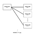
- FIG. 1 is a diagram schematically illustrating a configuration example of a video viewing system 100 for viewing video.
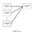
- FIG. 2 is a diagram schematically illustrating a configuration example of a video viewing system 200 for viewing video.
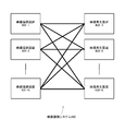
- FIG. 3 is a diagram schematically illustrating a configuration example of a video viewing system 300 for viewing a video.
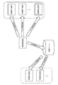
- FIG. 4 is a diagram schematically illustrating a configuration example of a video viewing system 400 for viewing video.
- FIG. 5 is a diagram schematically illustrating a functional configuration of an information processing apparatus 500 that can function as a video providing apparatus.
- FIG. 6 is a diagram schematically illustrating a functional configuration of an information processing apparatus 600 that can function as a video reproduction apparatus.
- FIG. 7 is a diagram for explaining a mechanism for viewing archived video.
- FIG. 1 is a diagram schematically illustrating a configuration example of a video viewing system 100 for viewing video.
- FIG. 2 is a diagram schematically illustrating a configuration example of a video viewing system 200 for viewing video.
- FIG. 8 is a diagram showing an example in which the video viewing system 100 is applied to an appearance of a real estate property.
- FIG. 9 is a diagram showing an example in which the video viewing system 100 is applied to an appearance of a real estate property.
- FIG. 10 is a diagram illustrating an example of a movement route when an archive video is captured at a real estate property.
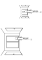
- FIG. 11 is a diagram showing an example in which real-time video 1101 and archive video 1102 are combined.
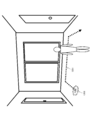
- FIG. 12 is a diagram illustrating an example in which information at the time of recording an archive video is superimposed and displayed on a real-time video currently captured by the video providing apparatus.
- FIG. 13 is a diagram showing an example of displaying a movement locus and a reproduction start position marker on an image of a map (room floor plan or the like).
- FIG. 14 is a flowchart showing a processing procedure when the distribution server switches from real-time video distribution to archive video distribution.
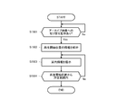
- FIG. 15 is a flowchart showing a processing procedure for aligning the real-time video with the video at the playback start position of the archive video, which is performed by the video providing apparatus.
- FIG. 1 schematically shows a configuration example of a video viewing system 100 for viewing video.
- the video viewing system 100 includes one video providing device 101 that provides video and one video playback device 102 that plays back video, and constitutes a one-to-one network topology.
- the video providing apparatus 101 and the video reproduction apparatus 102 are interconnected via a wide area network such as a wireless or wired LAN (Local Area Network) or the Internet, for example.
- a wide area network such as a wireless or wired LAN (Local Area Network) or the Internet, for example.
- LAN Local Area Network
- the video providing apparatus 101 is an information terminal operated by, for example, a user (property of a property or a salesman of a real estate company) in a real estate property (local site).
- the video providing apparatus 101 may be a fixed-point camera installed on the site or a camera mounted on a robot that operates autonomously on site.
- the video playback device 102 does not go to the local area, but considers a user (such as a real estate company store or home) who browses property information (for example, a real estate purchase or rental contract).
- Information terminal operated by a customer operated by a customer).
- the video providing apparatus 101 includes an imaging unit that captures a video (for example, a viewpoint video of a salesman located in a real estate property) having the installation position of the video providing apparatus 101 as a viewpoint, and the video playback apparatus 102 displays the captured video.
- a video for example, a viewpoint video of a salesman located in a real estate property
- the video playback apparatus 102 displays the captured video.
- the imaging unit may be configured with one omnidirectional camera. However, even if it is an all-round image, it is not necessary to be 360 degrees, and a part of the visual field may be missing (the same applies hereinafter).
- the video providing apparatus 101 further includes an audio input unit such as a microphone, and multiplexes the audio collected from the imaging scene of the whole sky video with the video and transmits the multiplexed audio to the video playback apparatus 102. Also good. For example, a salesman located in a real estate property may collect voices explaining the location conditions and floor plans of the property and transmit them to the video playback device 102.
- an audio input unit such as a microphone
- the video providing apparatus 101 may include a display unit.
- the display unit (or video providing apparatus 101 itself) is configured as a transmissive head-mounted display, for example. Users in the local area wear this head-mounted display on their heads, and perform local shooting and explanation of the property while referring to the images displayed on the head-mounted display as seen through.
- One video playback device 102 includes a display unit that displays the video received from the video providing device 101.
- the video playback device 102 (or its display unit) is configured as, for example, a head-mounted display that a user wears on the head and views the video.
- the video reproduction device 102 cuts out and displays a predetermined angle of view from the all-sky video (video obtained by imaging the room of the real estate property) captured by the video providing device 101.
- the video playback device 102 may be configured as a dome-type display, and may display all the sky images captured at the place where the video providing device 101 is installed.
- the video playback device 102 may be a normal (or large screen) monitor display.
- the video playback device 102 includes an audio output unit such as a speaker or a headphone, and the audio transmitted from the video providing device 101 in a multiplexed manner with the video (for example, a salesman in the local area of a real estate property determines the location conditions of the property Or audio explaining the floor plan) may be reproduced and output together with the video.
- an audio output unit such as a speaker or a headphone
- the video reproduction device 102 may further include a voice input unit such as a microphone, and may input a voice instruction from the user.
- a voice instruction such as “I want to see the view on the veranda” or “Show my living room”, and such an instruction is transmitted to the video providing device 101.
- the video providing apparatus 101 once transmits the all-sky image captured at the site to the distribution server 103.
- the distribution server 103 transmits to the video playback device 102 all-round video or video for a predetermined angle of view cut out from the full-sky video.
- the distribution server 103 also archives video received from the video providing apparatus 101.
- one video providing apparatus 101 and one video playback apparatus 102 constitute a one-to-one network topology.
- this corresponds to an embodiment in which a video captured by one video providing apparatus 101 installed in a specific property is viewed between one video playback apparatus 102 installed in a real estate store.
- Customers can view real-time video of the property in a form that is close to the actual feeling without visiting the local area, so that it is possible to achieve an efficient look and improve customer satisfaction.
- FIGS. 2 to 4 show modified examples of the video viewing system 100 for viewing the whole sky video.
- the distribution server is omitted, but it should be understood that the distribution server is interposed between the video providing apparatus and the video reproduction apparatus in any case.
- the video viewing system 200 shown in FIG. 2 has a one-to-N network topology with one video providing device 201 and a plurality (N) of video playback devices 202-1, 202-2,. All-round images captured by one image providing apparatus 201 (the same image captured at the same viewpoint position and in the same line of sight) are respectively reproduced by the image reproducing apparatuses 202-1, 202-2,. It is designed to be viewed simultaneously on 202-N.
- an image of a property imaged by one image providing device 201 installed in a specific property is installed in a plurality of units installed in a real estate store (or installed in a plurality of branches of a real estate company). This corresponds to an embodiment of viewing with the video playback devices 202-1, 202-2,..., 202-N. Since a plurality of customers can share and view a real-time video of one property, an efficient preview can be realized for a real estate company.
- FIG. 3 includes a plurality of (N) video providing apparatuses 301-1, 301-2,..., 301-N and one video reproducing apparatus 302, which is an N-to-1 network network. Topology is configured, and one video playback device 302 selectively receives video from any one of video providing devices 301-1, 301-2, ..., 301-N installed at different locations. It is to be displayed. Assume that the video reproduction device 302 can dynamically switch the video transmission source among the video providing devices 301-1, 301-2,..., 301-N.
- the viewpoint position of the video that is played back (viewable) by the video playback device 302 is switched (the viewpoint position is instantaneously changed to the installation location of the selected video providing device 301). Moving). Further, it is assumed that the video reproduction device 302 can instruct the selected video providing device 301 to switch the line-of-sight direction.
- one video playback device 302 installed in a real estate store switches videos from a plurality of video providing devices 301-1 301-2, 301-N installed in a plurality of properties, respectively. This corresponds to an embodiment of viewing while viewing.
- an embodiment is also assumed in which videos of a plurality of video providing apparatuses 301-1, 301-2,..., 301-N installed in each real estate property room are viewed while being switched by the video playback apparatus 302. Is done. Customers can view real-time video of each property at a stroke without having to move around the property at a stroke, so that an efficient look can be realized and customer satisfaction is improved.
- the N-to-N network topology may include the one-to-one network shown in FIG. 1, the one-to-N network shown in FIG. 2, and the N-to-one network shown in FIG.
- each of a plurality of video playback devices 402-1, 402-2,..., 402-N installed in a real estate store (or installed in each of a plurality of branches of a real estate company) .., 401-N are viewed while being switched.
- Each customer can view the real-time video of each property at a stroke without having to move around the property, making it possible to achieve an efficient look and improve customer satisfaction. .
- audiovisual data may be centrally managed by a distribution server.
- the audiovisual data of each video playback device is shared and shared with each other. You may make it use each other.
- the archive video is distributed from the distribution server, the result of counting the past audiovisual data may be used.
- FIG. 5 schematically shows a functional configuration of an information processing device 500 that can function as a video providing device in the video viewing systems 100 to 400.
- the illustrated information processing apparatus 500 includes an imaging unit 501, a video encoding unit 503, an audio input unit 504, an audio encoding unit 505, a multiplexing unit (MUX) 506, a communication unit 507, and a video decoding unit. 508, an image processing unit 509, a display unit 510, an audio decoding unit 511, an audio output unit 512, and a control unit 513.
- MUX multiplexing unit
- the imaging unit 501 includes a single-lens camera (including a wide-angle camera and a fish-eye camera), a two-lens stereo camera, a multi-lens omnidirectional camera, and the like. If a stereo camera is used, a sense of depth can be given to the video.
- the imaging unit 501 images the surroundings with the place where the information processing apparatus 500 is installed as the viewpoint position.
- the video encoding unit 503 performs encoding processing of the video signal captured by the imaging unit 501.
- the video imaged by the imaging unit 501 is distributed as a real-time video image (via a distribution server) to the video playback device, or is recorded as an archive video image by the distribution server.
- the audio input unit 504 is configured with, for example, a small microphone, a stereo microphone, and the like, and can be collected together with the imaging unit 501 to collect the sound at the imaging site of the whole sky video. If a stereo microphone is used, the sound at the time of sound collection can be reconstructed three-dimensionally on the playback side (that is, the video playback device).
- the voice encoding unit 505 encodes the voice signal input by the voice input unit 504.
- the multiplexing unit 506 multiplexes the encoded video signal and the encoded audio signal encoded by the video encoding unit 503 and the audio encoding unit 505, respectively, and transmits the signal to the video reproduction apparatus via the distribution server. Form into a format (packet).
- the display unit 510 (or the entire video providing apparatus 500) is configured as a transmissive head-mounted display, for example.
- the display unit 510 (or the entire video providing apparatus 500) is configured as a portable information terminal (with a camera) such as a smartphone or a tablet.
- the display unit 510 overlays and displays an image in the field of view of the user who images the property on site.
- the video decoding unit 508 decodes archive video received from, for example, a distribution server.
- the image processing unit 510 performs processing such as image recognition of the image captured by the imaging unit 501 and the video decoded by the video decoding unit 508, and generates a video to be displayed on the display unit 510.
- the display unit 510 displays guidance information such as a destination and a movement route to the user.
- the audio decoding unit 511 performs a decoding process on an encoded audio signal received from, for example, a video reproduction device.
- the audio output unit 512 outputs the decoded baseband audio signal as audio. For example, a voice instruction such as “I want to see the view on the veranda” or “Show me the living room” from the user of the video playback device is output as voice.
- the communication unit 507 performs mutual communication with the video reproduction device, including transmission of video and audio. However, it is assumed that a distribution server (described above) intervenes in communication with the video reproduction device.
- the communication unit 507 performs mutual communication with a video reproduction device, a distribution server, and other external devices through a wide area network such as a wireless or wired LAN or the Internet, for example.
- the control unit 513 comprehensively controls the operations of the units 501 to 512 described above. For example, the control unit 513 performs processing for realizing real-time communication with a video playback device (or a viewing group) that is a video transmission destination, and the display unit 510 uses a user (thing for photographing a property locally). ) Is displayed. In addition, the control unit 513 turns on / off an imaging operation and an audio input operation in order to limit a range of information to be provided according to attribute information of a video reproduction device (or a viewing group) that is a video transmission destination. Mosaic, mask processing, and input audio modulation processing are performed on the captured video.
- FIG. 6 schematically shows a functional configuration of an information processing device 600 that can function as a video reproducing device in the video viewing systems 100 to 400.
- the illustrated information processing apparatus 600 includes a communication unit 601, a separation unit (DEMUX) 602, an audio decoding unit 603, an audio output unit 604, a video decoding unit 605, a display unit 606, a sound collection unit 607, A voice encoding unit 608, a sensor unit 609, a control unit 610, and an external device interface 611 are provided.
- a communication unit 601 a separation unit (DEMUX) 602
- an audio decoding unit 603 an audio output unit 604
- a video decoding unit 605 a display unit 606, a sound collection unit 607
- a voice encoding unit 608, a sensor unit 609, a control unit 610, and an external device interface 611 are provided.
- the respective units 601 to 611 will be described.
- the communication unit 601 performs mutual communication with the video providing apparatus, including transmission of video and audio. Further, communication with the distribution server (described above) is performed via the communication unit 601 as necessary.
- the communication unit 601 performs mutual communication with a video providing device, a distribution server, and other external devices through a wide area network such as a wireless or wired LAN or the Internet.
- a video or audio transmission start request is transmitted from the communication unit 601 to a video providing apparatus installed in a place where a video is desired to be viewed (for example, a real estate property that is desired to be viewed).
- the communication unit 601 receives a transmission signal formed in a predetermined signal format (packet) from the video providing apparatus.
- a video received from a video providing device is being displayed (that is, being viewed by a user) and the user wants to see a different gaze direction at the viewpoint position
- the gaze direction change request is transmitted from the communication unit 601.
- a transmission stop request is transmitted from the communication unit 601 to the video providing device that is receiving the video or audio, and a transmission start request is sent to the destination video providing device. Is transmitted from the communication unit 601.
- the separating unit 602 separates the signal multiplexed and transmitted from the video providing apparatus into an encoded video signal and an encoded audio signal, and distributes them to the audio decoding unit 603 and the video decoding unit 605, respectively.
- the audio decoding unit 603 generates a baseband audio signal by decoding the encoded audio signal, and outputs the audio from the audio output unit 604.
- the audio output unit 604 includes monaural, stereo, multi-channel speakers, and the like.
- the video decoding unit 605 decodes the encoded video signal to generate a baseband video signal, and displays the video captured by the transmission source video providing apparatus on the display unit 606.
- the display unit 606 (or the information processing apparatus 600 main body) is configured by, for example, a head-mounted display, a dome-type display, or a large screen (or normal) monitor display.
- the sound collection unit 607 is constituted by a small microphone or a stereo microphone, for example, and collects a user's voice and the like.
- the audio encoding unit 608 encodes the audio signal input by the sound collection unit 607 and outputs the encoded audio signal to the control unit 610. If the user's voice is an impression or admiration for the video displayed on the display unit 606, or a voice instruction to the control unit 610 (or video playback device) (for example, changing the line-of-sight direction of the all-sky image) There is also.
- the user of the video playback device can give a voice instruction such as “I want to see the view of the veranda” or “Show the living room” while viewing the video of the property of the property that I want to see on the display unit 606. .
- a voice instruction such as “I want to see the view of the veranda” or “Show the living room” while viewing the video of the property of the property that I want to see on the display unit 606.
- Such user's voice is collected by the sound collection unit 607, encoded by the audio encoding unit 608, and then transmitted from the communication unit 601 to the video providing apparatus.
- the control unit 610 controls the output of video and audio received from the video providing device.
- the control unit 610 controls display of UI and OSD (On-Screen Display) on the screen of the display unit 606, and processes operations performed by the user (viewer) on the UI and OSD.
- UI and OSD On-Screen Display
- the sensor unit 609 measures the line-of-sight direction, the head position, or the posture of the user (a viewer who views the video displayed on the screen of the display unit 606).
- the sensor unit 609 is configured by combining a plurality of sensor elements such as a gyro sensor, an acceleration sensor, and a geomagnetic sensor, for example (a total of 9 axes including a 3-axis gyro sensor, a 3-axis acceleration sensor, and a 3-axis geomagnetic sensor can be detected. Sensor).
- the sensor unit 609 may be integrated with the main body of the information processing apparatus 600 (head mount, display, etc.), or may be an accessory part attached to the main body.
- Operations such as the user's line-of-sight direction, head position, or posture detected by the sensor unit 609 (or gesture operations using not only the head but also the torso and limbs) are displayed on the UI displayed on the display unit 609.
- this may mean an instruction of an angle of view to be displayed on the display unit 609 in the whole sky video.
- the horizontal and vertical swinging of the user can be handled as an instruction to change the line-of-sight direction in the all-sky video.
- an operation in which the user tilts the body forward or backward may be handled as a zoom operation of the camera in the current line-of-sight direction (zoom up if tilted forward, zoom down if tilted backward). Then, the detection result of the sensor unit 609 is output to the control unit 610.
- the control unit 610 is receiving a signal based on the user's line-of-sight direction detected by the sensor unit 609, horizontal and vertical head swings (right or left, looking up, looking down, etc.) or a change in posture.
- An instruction to change the line-of-sight direction for viewing the all-sky video is transmitted via the communication unit 601.
- the control unit 610 transmits the voice instruction of the user collected by the sound collection unit 607 to the video providing apparatus via the communication unit 601 after converting the voice instruction as it is or into text information or command information.
- control unit 610 operates when the user's line-of-sight direction, head, and posture operations (or gesture operations using not only the head but also the torso and limbs) are operations on the UI and OSD on the screen. Performs processing on the display image of the display unit 606 according to this operation.
- An external device interface (IF) 611 connects an external device to the information processing apparatus 600 in accordance with an interface standard such as USB (Universal Serial Interface).
- the information processing apparatus 600 can connect a well-known input device (none of which is shown) such as a keyboard, mouse, touch panel, joystick, and game controller to the external device interface 611.
- a well-known input device such as a keyboard, mouse, touch panel, joystick, and game controller to the external device interface 611.
- This type of input device may be used for input operations on the UI and OSD on the screen of the display unit 606, and for instructions for moving the imaging position of the all-sky video and switching the line of sight.
- FIG. 7 shows a mechanism for delivering an archive video recorded to an external device to the video playback device, instead of directly transmitting a real-time video from the video providing device.
- the external device referred to here is, for example, a distribution server that is installed physically independently of the video providing device and that records the video or distributes the recorded video. It is possible to distribute the load on the video providing apparatus by entrusting the distribution server to distribute the video to the video playback apparatus that has been kicked out at the time or time specified by the video playback apparatus.
- a video playback device that has been kicked out of the capacity cannot view live images taken at the installation location (viewpoint position) of the video providing device, but can relive it as long as time delay is allowed. Can do.
- Real-time video captured by each video provider is also sent to the distribution server.
- the received video is the information for identifying the video providing device of the transmission source, the captured viewpoint position (the property in which the video providing device is installed, the room in the property), the captured time zone, and the captured environment. Etc. are recorded in association with information that can be specified.
- a transmission start request is sent from the video playback device to instruct the switching of the imaging environment such as time zone, season, and weather
- the archive video recorded in the external device is transmitted from the real-time video transmission from the video providing device. Switch to.
- the preview 8 estate shows an example of application of the display system 100 of the real estate to the preliminary inspection.
- Reference numeral 801 denotes a user (such as an inspector of a property or a salesman of a real estate company) in a real estate property (local), and possesses or equips a video providing device (described above).
- the reference number 802 is a user who browses property information in a place (for example, a real estate company's store or home) that does not go to the site and is remote from the site, and uses a video playback device (described above), You are watching a video of a property captured by the video provider.
- the user 801 walks around the property, explains the location conditions, floor plan, equipment, etc. of the property, gives impressions, and opens the door to change the location. Look around the room.
- the other user 802 can view the real-time video of the property in a form that is close to the real feeling without going to the local area, so that an efficient appearance can be realized. That is, when the video viewing system 100 is applied to a real estate preview, customer satisfaction is improved.
- Switching from real-time video to archive video may be instructed from either the video providing device or the video playback device.
- a user of a video providing apparatus located in a local area such as a salesman of a real estate company wants to show a video of another time zone of the property
- he / she instructs to switch to an archive video.
- a user of a video playback device is watching a real-time video of a property being imaged by a video providing device and wants to see the situation in another time zone or other season of the property, the user can view the archive video. Is instructed to switch.
- the video playback device can use, for example, “morning”, “noon”, “night” , “Spring”, “Summer”, “Autumn”, “Winter”, and the like may be displayed to request switching from the real-time video to the archive video.
- the imaging position of the real-time video and the imaging position of the archive video are separated by only about several tens of centimeters at the switching timing, the snapping process or the image synthesis (when 3D measurement is possible, 3D
- the video can be switched continuously by animation or the like, or the discontinuity of the video is acceptable for the viewer.
- the real-time video captured at the imaging position that coincides with the imaging position at the time when the viewing of the archive video ends (or within a predetermined distance) is switched. It is preferable to make it. That is, when the reproduction of the archived video is finished, the user 801 (video providing device) needs to move and wait until the imaging position at the time when the reproduction is finished.
- the imaging position referred to here including not only the horizontal position but also the vertical position. Even if the horizontal position matches and the vertical position is far off, even if you look at the same object in the room, if the angle to look up or look down is different, it gives the impression that the video switched discontinuously End up.
- the archive video to be switched is captured while moving along the path indicated by reference number 1002 with reference number 1001 in FIG. 10 as the start position, and the imaging is ended at the end position indicated by reference number 1003.
- the real-time video captured near the archive video playback start position 1001 is switched from the real-time video to the archive video, the video can be continuously switched by image synthesis, or the video can be viewed by a viewer. Discontinuity is an acceptable range.
- switching to real-time video captured near the playback end position 1003 of the archive video enables continuous video switching by image composition. Yes, or the discontinuity of the image is acceptable for the viewer.
- a physical mark that can visually recognize the reproduction start position 1001 and the reproduction end position 1003 is attached to the floor or the like, a user who is capturing a real-time video can grasp the mark. By walking around the property and switching to the archive video when approaching the landmark, the video playback device can view the archive video that is continuously switched from the real-time video.
- a large number of landmarks must be placed, which makes the appearance worse and makes it difficult to understand which archive video position is indicated.
- FIG. 11 shows an example in which real-time video 1101 and archive video 1102 are combined.
- the user of the video providing apparatus that captures the real-time video searches for a place (imaging position) where the real-time video overlaps the archive video. Then, if the distribution server switches to the archive video when it is sufficiently overlapped, the video playback device can view the video that is continuously switched from the real-time video to the archive video.
- the display unit 510 (or the video providing device itself) is configured as a transmissive head-mounted display
- switching to the archive video is performed by searching for a field of view that overlaps the archive video displayed in a see-through manner. You can find a suitable place.
- image processing such as edge processing or alpha blending may be applied to the archive video in order to make it easy to view the real-time video through the archive video even after image synthesis.
- the technique for guiding to an appropriate imaging position there can be mentioned a method of visually presenting information related to a movement locus at the time of imaging an archive video.
- the movement trajectory 1201 at the time of capturing the archive video or the reproduction start position 1202 that is one end of the movement trajectory 1201 is superimposed on the real-time video currently captured by the video providing apparatus. If displayed, the user can easily understand where to proceed when switching to the archive video.
- the information of the reproduction start position 1202 may be displayed not as a point but as an area in a range where video switching is possible (or switching is allowed) by image synthesis or the like.
- the movement trajectory 1301 and the reproduction start position marker 1302 are displayed on the image of the map (room floor plan, etc.). It may be.
- a map of the movement trajectory of the camera (video providing apparatus) at the time of capturing the archive video is recorded.
- the method of presenting information related to the movement trajectory is more difficult to implement than the method of overlay display of the edge processed image and alpha blend image of the archive video.
- an algorithm such as SLAM (Multiple Localization and Mapping) can be used to create the map.
- the distribution server performs image matching between the real-time video captured by the video providing device and the archive video at the playback start position, and switches the video at a timing when the matching is sufficiently achieved.
- image matching cannot be achieved completely, it may be in a range where video can be continuously switched by image synthesis.
- information on the current position of the video providing apparatus may be acquired, and video switching may be performed at a timing sufficiently close to the archive video playback start position.
- the current position of the video providing apparatus can be estimated by the SLAM technology using, for example, a real-time video captured by the imaging unit 501.
- the distribution server may pause the playback of the archive video on the video playback device and wait for the switching until the video providing device enters an appropriate position.
- the reproduction of the archive video may be continued after the end position.
- switching to the real-time video may be performed at the timing when the real-time video captured by the video providing device matches the archive video at the current playback position.
- FIG. 14 shows a processing procedure executed in the distribution server in the form of a flowchart when the video displayed on the video playback device is switched from the real-time video to the archive video. It is assumed that the illustrated processing procedure is executed during delivery of real-time video to the video playback device.
- the distribution server distributes the real-time video to the video playback device, if the video playback device or the video providing device instructs to switch to the archive video (Yes in step S1401), the distribution server requests the archive video requested.
- the video at the reproduction start position is read out, the difference from the real-time video is calculated (step S1402), and it is checked whether or not switching from the archive video to the real-time video is possible (step S1403).
- step S1403 If the difference between the real-time video and the archive video at the playback start position is equal to or smaller than a predetermined value, it is determined that the switch from the archive video to the real-time video is possible (Yes in step S1403). For example, if the imaging position of the real-time video and the imaging position of the archive video are only a few tens of centimeters apart, snapping processing or image synthesis (if 3D measurement is possible, the video is re-synthesized in 3D It is possible to determine that the video can be switched continuously by animation or the like, or that the discontinuity of the video is permissible for the viewer, and switching from the real-time video to the archive video is possible.
- the distribution server requests the video providing apparatus to align the real time video (step S1404). This request is accompanied by information such as the video at the playback start position of the archive video. Then, while the real-time video alignment processing is performed in the video providing device, the distribution server refrains from switching to the archive video and continues to deliver the real-time video sent from the video providing device to the video reproducing device (step). S1405).
- the distribution server sends the video to the video playback device.
- the distribution video is switched from the real-time video to the archive video (step S1406).
- the distribution server When switching to archive video and then returning to real-time video distribution again, the distribution server requests the video providing device to align the real-time video and archives the real-time video and the playback start position. The transmission of the archive video to the video playback device is continued until the video difference becomes a predetermined value or less and switching to the real-time video becomes possible.
- FIG. 15 shows a processing procedure for aligning the real-time video with the video at the playback start position of the archive video, which is performed by the video providing device when the video displayed on the video playback device is switched from the real-time video to the archive video. It is shown in the form of a flowchart. It is assumed that the processing procedure illustrated is executed while the video providing apparatus is capturing and transmitting real-time video.
- step S1501 When an instruction to switch to archive video is input from the user to the video providing device or switching to archive video is instructed via the distribution server (Yes in step S1501), the video at the playback start position of the archive video is acquired. And analyzing (step S1502).
- the video at the playback start position of the archive video may be acquired from the distribution server, or may be acquired from the archive video stored by the video providing apparatus itself.
- step S1503 guide information for guiding the user of the video providing apparatus to an appropriate imaging position is presented (step S1503).
- the display unit 510 may superimpose and display the video at the reproduction start position of the archive video on the real-time video.
- the display unit 510 or the video providing apparatus itself
- the video at the playback start position of the archive video may be displayed in a see-through manner.
- image processing such as edge processing and alpha blending may be performed on the video at the playback start position so that the real-time video can be easily viewed through the archive video (see FIG. 11).
- the video providing apparatus may output from the audio output unit 512 a voice guidance that teaches which neighborhood of the room should be approached. Voice guidance may be performed together with the superimposed display of the video at the playback start position (above).
- the display unit 510 may display the movement trajectory at the time of capturing the archive video and the information of the reproduction start position, which is one end of the movement trajectory, superimposed on the real-time video.
- step S1504 Until the difference between the real-time video and the video at the playback start position of the archive video is within a predetermined range and switching to the archive video is possible (No in step S1504), the process returns to step S1503 and continues to present guidance information. Moreover, the content of guidance information is updated as needed.
- the video providing apparatus ends this process.
- the video providing apparatus guides the alignment of the video at the reproduction end position of the archive video and the real-time video. The same guidance information is presented.
- a real-time image or an archive image captured of a real estate property can be suitably viewed, and a realistic look can be realized even from a remote location of the property. Can do.
- the present specification has been described mainly with respect to an embodiment in which the technology disclosed in this specification is applied to a real estate property inspection system, the gist of the technology disclosed in this specification is not limited thereto. .
- the technology disclosed in this specification can be applied to video transmission in various industrial fields. For example, medical sites such as surgery, construction sites such as civil engineering, airplane and helicopter operations, car driver navigation, sports instruction and coaching, various industrial work support, nursing support, human resource dispatch Can be used for applications.
- the technology disclosed in this specification can be used for concerts, sports watching, and SNS (Social Network Service).
- an imaging unit A transmission unit that transmits an image captured by the imaging unit;
- a control unit Comprising The control unit controls alignment of a current image currently captured by the imaging unit and a past image captured in the past.
- Information processing terminal device (2) further comprising a display unit;
- the control unit causes the display unit to display information for aligning with a past image.
- the control unit causes the display unit to display the past image superimposed on the current imaging.
- the control unit causes the display unit to display the past image after the edge processing, alpha blending processing, or other image processing is superimposed on the current image.
- the control unit causes the display unit to display information on a movement locus at the time of imaging the past video.
- the information processing terminal device according to (2) above.
- (6) a transmission unit that transmits an image captured by the first device to the second device; A control unit for controlling image transmission by the transmission unit; Comprising The control unit controls switching of a distribution image between a current image currently captured by the first device and a past image captured in the past; Distribution device.
- the control unit controls switching of distribution images according to a difference between the current image and the past image.
- the control unit does not switch the distribution image until the difference between the current image and the past image is within a predetermined range.
- DESCRIPTION OF SYMBOLS 100 ... Video viewing system 101 ... Video provision apparatus, 102 ... Video reproduction apparatus 200 ... Video viewing system 201 ... Video provision apparatus, 202 ... Video reproduction apparatus 300 ... Video viewing system 301 ... Video provision apparatus, 302 ... Video reproduction apparatus 400 ... Video viewing system 401 ... Video providing device, 402 ... Video playback device 500 ... Information processing device (video providing device) 501: Imaging unit, 503: Video encoding unit 504 ... Audio input unit, 505 ... Audio encoding unit 506 ... Multiplexing unit, 507 ... Communication unit, 508 ... Video decoding unit 509 ... Image processing unit, 510 ... Display unit, 511 ... Audio decoding unit 512 ...
- Audio output unit 513 ... Control unit 600 ... Information processing device (video reproduction device) 601 ... Communication unit, 602 ... Separation unit (DEMUX) 603: Audio decoding unit, 604 ... Audio output unit 605 ... Video decoding unit, 606 ... Display unit 607 ... Sound collecting unit, 608 ... Audio encoding unit, 609 ... Sensor unit 610 ... Control unit, 611 ... External device interface
Landscapes
- Engineering & Computer Science (AREA)
- Multimedia (AREA)
- Signal Processing (AREA)
- Databases & Information Systems (AREA)
- General Physics & Mathematics (AREA)
- Physics & Mathematics (AREA)
- Theoretical Computer Science (AREA)
- Astronomy & Astrophysics (AREA)
- Business, Economics & Management (AREA)
- Marketing (AREA)
- General Engineering & Computer Science (AREA)
- Two-Way Televisions, Distribution Of Moving Picture Or The Like (AREA)
- Information Transfer Between Computers (AREA)
Abstract
L'invention concerne un dispositif terminal de traitement d'informations qui transmet une image capturée et un dispositif de distribution qui commande la distribution de l'image capturée. Une unité d'affichage (510) d'un dispositif de fourniture vidéo combine et affiche une vidéo d'archive sur le point d'être commutée avec une vidéo en temps réel en cours de capture. La vidéo archivée peut éventuellement être soumise à un traitement d'image tel qu'un traitement de contour ou une simulation de transparence. L'utilisateur du dispositif de fourniture vidéo recherche un emplacement où la vidéo en temps réel chevauche la vidéo d'archives. En outre, le serveur de distribution commute vers la vidéo d'archives à un moment où le chevauchement a été suffisant.
Priority Applications (2)
| Application Number | Priority Date | Filing Date | Title |
|---|---|---|---|
| US16/095,668 US20190132614A1 (en) | 2016-04-28 | 2017-02-28 | Information processing terminal apparatus and distribution apparatus |
| JP2018514154A JPWO2017187764A1 (ja) | 2016-04-28 | 2017-02-28 | 情報処理端末装置並びに配信装置 |
Applications Claiming Priority (2)
| Application Number | Priority Date | Filing Date | Title |
|---|---|---|---|
| JP2016090107 | 2016-04-28 | ||
| JP2016-090107 | 2016-04-28 |
Publications (1)
| Publication Number | Publication Date |
|---|---|
| WO2017187764A1 true WO2017187764A1 (fr) | 2017-11-02 |
Family
ID=60160281
Family Applications (1)
| Application Number | Title | Priority Date | Filing Date |
|---|---|---|---|
| PCT/JP2017/007707 Ceased WO2017187764A1 (fr) | 2016-04-28 | 2017-02-28 | Dispositif terminal de traitement d'informations et dispositif de distribution |
Country Status (3)
| Country | Link |
|---|---|
| US (1) | US20190132614A1 (fr) |
| JP (1) | JPWO2017187764A1 (fr) |
| WO (1) | WO2017187764A1 (fr) |
Cited By (5)
| Publication number | Priority date | Publication date | Assignee | Title |
|---|---|---|---|---|
| WO2022201735A1 (fr) * | 2021-03-25 | 2022-09-29 | 日立建機株式会社 | Dispositif de présentation d'informations |
| JP2023073307A (ja) * | 2019-01-24 | 2023-05-25 | 株式会社バンダイナムコエンターテインメント | プログラム、電子機器およびデータ記録方法 |
| JP2023095696A (ja) * | 2021-12-24 | 2023-07-06 | 株式会社エクシング | コンテンツ配信システム、及び、カラオケ再生システム |
| JP7462199B1 (ja) | 2023-06-14 | 2024-04-05 | 株式会社インフォシティ | 番組受信表示装置及び番組受信表示制御方法 |
| JP7614256B1 (ja) | 2023-06-26 | 2025-01-15 | レノボ・シンガポール・プライベート・リミテッド | 情報共有システム、ウェアラブル装置、情報共有方法、及び情報共有プログラム |
Families Citing this family (1)
| Publication number | Priority date | Publication date | Assignee | Title |
|---|---|---|---|---|
| US10575030B2 (en) * | 2016-06-22 | 2020-02-25 | DeNA Co., Ltd. | System, method, and program for distributing video |
Citations (2)
| Publication number | Priority date | Publication date | Assignee | Title |
|---|---|---|---|---|
| JPH08221592A (ja) * | 1995-02-16 | 1996-08-30 | Matsushita Electric Ind Co Ltd | 対話型情報提供装置 |
| JP2005026872A (ja) * | 2003-06-30 | 2005-01-27 | Casio Comput Co Ltd | 撮影方法、撮像装置、及びプログラム |
Family Cites Families (7)
| Publication number | Priority date | Publication date | Assignee | Title |
|---|---|---|---|---|
| WO2003039143A1 (fr) * | 2001-10-30 | 2003-05-08 | Nikon Corporation | Appareil d'accumulation d'images, appareil de support d'accumulation d'images, systeme d'accumulation d'images, appareil de commande d'images, appareil de stockage d'images |
| US7130472B2 (en) * | 2002-01-21 | 2006-10-31 | Canon Kabushiki Kaisha | Image distribution apparatus, communication terminal apparatus, and control method thereof |
| JP2004226140A (ja) * | 2003-01-21 | 2004-08-12 | Sony Corp | 情報端末装置、ナビゲーションシステム、および情報処理方法、並びにコンピュータ・プログラム |
| US7409105B2 (en) * | 2003-10-22 | 2008-08-05 | Arcsoft, Inc. | Panoramic maker engine for a low profile system |
| JP4697221B2 (ja) * | 2007-12-26 | 2011-06-08 | ソニー株式会社 | 画像処理装置、動画再生装置、これらにおける処理方法およびプログラム |
| WO2009090901A1 (fr) * | 2008-01-15 | 2009-07-23 | Comap Incorporated | Dispositif, procédé et programme de génération d'images en mosaïque |
| US9626589B1 (en) * | 2015-01-19 | 2017-04-18 | Ricoh Co., Ltd. | Preview image acquisition user interface for linear panoramic image stitching |
-
2017
- 2017-02-28 US US16/095,668 patent/US20190132614A1/en not_active Abandoned
- 2017-02-28 WO PCT/JP2017/007707 patent/WO2017187764A1/fr not_active Ceased
- 2017-02-28 JP JP2018514154A patent/JPWO2017187764A1/ja active Pending
Patent Citations (2)
| Publication number | Priority date | Publication date | Assignee | Title |
|---|---|---|---|---|
| JPH08221592A (ja) * | 1995-02-16 | 1996-08-30 | Matsushita Electric Ind Co Ltd | 対話型情報提供装置 |
| JP2005026872A (ja) * | 2003-06-30 | 2005-01-27 | Casio Comput Co Ltd | 撮影方法、撮像装置、及びプログラム |
Cited By (16)
| Publication number | Priority date | Publication date | Assignee | Title |
|---|---|---|---|---|
| JP2023073307A (ja) * | 2019-01-24 | 2023-05-25 | 株式会社バンダイナムコエンターテインメント | プログラム、電子機器およびデータ記録方法 |
| JP7466730B2 (ja) | 2019-01-24 | 2024-04-12 | 株式会社バンダイナムコエンターテインメント | プログラム、電子機器およびデータ記録方法 |
| KR102796800B1 (ko) | 2021-03-25 | 2025-04-16 | 히다치 겡키 가부시키 가이샤 | 정보 제시 장치 |
| JPWO2022201735A1 (fr) * | 2021-03-25 | 2022-09-29 | ||
| KR20230043968A (ko) * | 2021-03-25 | 2023-03-31 | 히다치 겡키 가부시키 가이샤 | 정보 제시 장치 |
| JP7461567B2 (ja) | 2021-03-25 | 2024-04-03 | 日立建機株式会社 | 情報提示装置 |
| US12366055B2 (en) | 2021-03-25 | 2025-07-22 | Hitachi Construction Machinery Co., Ltd. | Information presentation device |
| WO2022201735A1 (fr) * | 2021-03-25 | 2022-09-29 | 日立建機株式会社 | Dispositif de présentation d'informations |
| JP2023095696A (ja) * | 2021-12-24 | 2023-07-06 | 株式会社エクシング | コンテンツ配信システム、及び、カラオケ再生システム |
| JP7549315B1 (ja) | 2023-06-14 | 2024-09-11 | 株式会社インフォシティ | 番組受信表示装置及び番組受信表示制御方法 |
| JP2024179361A (ja) * | 2023-06-14 | 2024-12-26 | 株式会社インフォシティ | 番組受信表示装置及び番組受信表示制御方法 |
| JP2024180272A (ja) * | 2023-06-14 | 2024-12-26 | 株式会社インフォシティ | 番組受信表示装置及び番組受信表示制御方法 |
| WO2024257692A1 (fr) * | 2023-06-14 | 2024-12-19 | 株式会社インフォシティ | Dispositif d'affichage de réception de programme et procédé de commande d'affichage de réception de programme |
| JP7462199B1 (ja) | 2023-06-14 | 2024-04-05 | 株式会社インフォシティ | 番組受信表示装置及び番組受信表示制御方法 |
| JP7614256B1 (ja) | 2023-06-26 | 2025-01-15 | レノボ・シンガポール・プライベート・リミテッド | 情報共有システム、ウェアラブル装置、情報共有方法、及び情報共有プログラム |
| JP2025010638A (ja) * | 2023-06-26 | 2025-01-23 | レノボ・シンガポール・プライベート・リミテッド | 情報共有システム、ウェアラブル装置、情報共有方法、及び情報共有プログラム |
Also Published As
| Publication number | Publication date |
|---|---|
| JPWO2017187764A1 (ja) | 2019-02-28 |
| US20190132614A1 (en) | 2019-05-02 |
Similar Documents
| Publication | Publication Date | Title |
|---|---|---|
| US10455184B2 (en) | Display device and information processing terminal device | |
| JPWO2017187764A1 (ja) | 情報処理端末装置並びに配信装置 | |
| US10531068B2 (en) | Information processing device, information processing method, and three-dimensional image data transmission method | |
| US9615177B2 (en) | Wireless immersive experience capture and viewing | |
| EP3238445B1 (fr) | Affichage vidéo binoculaire interactif | |
| US12452481B2 (en) | Video display system, information processing device, information processing method, and recording medium | |
| US11647354B2 (en) | Method and apparatus for providing audio content in immersive reality | |
| US20180278995A1 (en) | Information processing apparatus, information processing method, and program | |
| JP6822410B2 (ja) | 情報処理システム及び情報処理方法 | |
| JP2025081342A (ja) | 無人移動体を用いたライブ映像配信方法、該ライブ映像配信方法において用いられる映像配信装置、及び、該映像配信装置が生成する映像データファイルを保存する映像アーカイブ装置 | |
| WO2020031696A1 (fr) | Dispositif de traitement d'informations, procédé de traitement d'informations et système de sortie audio-vidéo | |
| EP3721333A1 (fr) | Système et procédé de lecture de vidéo à 360 degrés interactive basée sur l'emplacement de l'utilisateur | |
| WO2017187807A1 (fr) | Dispositif terminal de traitement d'informations | |
| US9979930B2 (en) | Head-wearable apparatus, 3D video call system and method for implementing 3D video call | |
| KR20190081447A (ko) | 스트리밍 글래스를 이용한 다국어 자막 및 사운드 제공 시스템 | |
| JP2022030985A (ja) | 情報処理装置、情報処理方法及び情報処理システム | |
| WO2021010761A1 (fr) | Système et procédé de fourniture de réalité remplacée |
Legal Events
| Date | Code | Title | Description |
|---|---|---|---|
| WWE | Wipo information: entry into national phase |
Ref document number: 2018514154 Country of ref document: JP |
|
| NENP | Non-entry into the national phase |
Ref country code: DE |
|
| 121 | Ep: the epo has been informed by wipo that ep was designated in this application |
Ref document number: 17789053 Country of ref document: EP Kind code of ref document: A1 |
|
| 122 | Ep: pct application non-entry in european phase |
Ref document number: 17789053 Country of ref document: EP Kind code of ref document: A1 |