WO2022201735A1 - Dispositif de présentation d'informations - Google Patents
Dispositif de présentation d'informations Download PDFInfo
- Publication number
- WO2022201735A1 WO2022201735A1 PCT/JP2022/000208 JP2022000208W WO2022201735A1 WO 2022201735 A1 WO2022201735 A1 WO 2022201735A1 JP 2022000208 W JP2022000208 W JP 2022000208W WO 2022201735 A1 WO2022201735 A1 WO 2022201735A1
- Authority
- WO
- WIPO (PCT)
- Prior art keywords
- image
- bird
- eye view
- construction site
- blind spot
- Prior art date
- Legal status (The legal status is an assumption and is not a legal conclusion. Google has not performed a legal analysis and makes no representation as to the accuracy of the status listed.)
- Ceased
Links
Images








Classifications
-
- E—FIXED CONSTRUCTIONS
- E02—HYDRAULIC ENGINEERING; FOUNDATIONS; SOIL SHIFTING
- E02F—DREDGING; SOIL-SHIFTING
- E02F9/00—Component parts of dredgers or soil-shifting machines, not restricted to one of the kinds covered by groups E02F3/00 - E02F7/00
- E02F9/26—Indicating devices
- E02F9/261—Surveying the work-site to be treated
- E02F9/262—Surveying the work-site to be treated with follow-up actions to control the work tool, e.g. controller
-
- G—PHYSICS
- G06—COMPUTING OR CALCULATING; COUNTING
- G06T—IMAGE DATA PROCESSING OR GENERATION, IN GENERAL
- G06T3/00—Geometric image transformations in the plane of the image
- G06T3/40—Scaling of whole images or parts thereof, e.g. expanding or contracting
- G06T3/4038—Image mosaicing, e.g. composing plane images from plane sub-images
-
- E—FIXED CONSTRUCTIONS
- E02—HYDRAULIC ENGINEERING; FOUNDATIONS; SOIL SHIFTING
- E02F—DREDGING; SOIL-SHIFTING
- E02F9/00—Component parts of dredgers or soil-shifting machines, not restricted to one of the kinds covered by groups E02F3/00 - E02F7/00
- E02F9/24—Safety devices, e.g. for preventing overload
-
- E—FIXED CONSTRUCTIONS
- E02—HYDRAULIC ENGINEERING; FOUNDATIONS; SOIL SHIFTING
- E02F—DREDGING; SOIL-SHIFTING
- E02F9/00—Component parts of dredgers or soil-shifting machines, not restricted to one of the kinds covered by groups E02F3/00 - E02F7/00
- E02F9/26—Indicating devices
- E02F9/261—Surveying the work-site to be treated
-
- G—PHYSICS
- G06—COMPUTING OR CALCULATING; COUNTING
- G06V—IMAGE OR VIDEO RECOGNITION OR UNDERSTANDING
- G06V20/00—Scenes; Scene-specific elements
- G06V20/50—Context or environment of the image
- G06V20/52—Surveillance or monitoring of activities, e.g. for recognising suspicious objects
Definitions
- the present disclosure relates to an information presentation device.
- Patent Literature 1 identifies the positions of each of a plurality of vehicles based on images captured by a plurality of imaging devices installed at a construction site, and arbitrarily selects one of the identified vehicles. It outputs a signal that displays the positions of other vehicles whose distance from the designated vehicle is less than the threshold value, superimposed on the bird's-eye view image of the construction site.
- Patent Document 1 when the number of imaging devices that can be used at a construction site is limited from the viewpoint of installation cost, it may be difficult to synthesize a bird's-eye view image. This is because an image that covers the entire construction site cannot be synthesized. This makes it impossible to efficiently manage a plurality of vehicles at the construction site.
- the present disclosure has been made in view of such circumstances, and proposes a technique for presenting an operator of a work machine with a bird's-eye view image of a work site even when the number of imaging devices at the construction site is insufficient. .
- an information presentation device that generates and outputs a topographic image related to a construction site, comprising: a storage device for storing a program for executing predetermined image processing on the topographic image; a processor that reads a program from the device and generates a terrain image, wherein the processor uses the image of the construction site acquired by at least one imaging device installed at the construction site to overlook the current topography of the construction site.
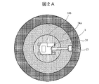
- FIG. 3 is a diagram showing a movable range 24 of the hydraulic excavator 1.
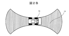
- FIG. 3 is a diagram showing a movable range 19 of a wheel loader 36;
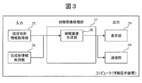
- FIG. 2 is a block diagram which shows the functional structural example of the information presentation apparatus by this embodiment.
- 2 is a diagram showing an example of a bird's-eye view image 2 acquired by an original topography information acquisition unit 26.
- FIG. 2 is a diagram showing an example of a bird's-eye view image 1 acquired by a current landform information acquisition unit 25.
- FIG. 3 is a diagram showing an example of a bird's-eye view image 3 generated by a bird's-eye view image synthesizing unit 28 by superimposing current landform information (bird's-eye view image 1) on original landform information (bird's-eye view image 2).
- 4 is a flowchart for explaining details of bird's-eye view image generation processing for generating bird's-eye view image 3 according to the present embodiment.
- FIG. 11 is a block diagram showing an example functional configuration of an information presentation device according to a second embodiment;
- FIG. 4 is a diagram (1) for explaining a method of calculating a blind spot 40 (presence or absence of a blind spot, position of the blind spot, width (size) of the blind spot).
- FIG. 2 is a diagram (2) for explaining a method of calculating a blind spot 40 (presence or absence of a blind spot, position of the blind spot, width (size) of the blind spot).
- FIG. 3 is a diagram (3) for explaining a method of calculating a blind spot 40 (presence or absence of a blind spot, position of the blind spot, width (size) of the blind spot).
- FIG. 10 is a diagram showing an example of a bird's-eye view image 4 (a bird's-eye view image generated by adding a blind spot to the bird's-eye view image 3) according to the second embodiment;
- FIG. 10 is a flowchart for explaining details of processing for generating a bird's-eye view image 4 according to the second embodiment;
- FIG. 11 is a block diagram showing an example of the functional configuration of an information presentation device according to a third embodiment
- FIG. 4 is a diagram showing an example of an in-vehicle bird's-eye view image 48.
- FIG. FIG. 11 is a diagram showing an example of a synthesized bird's-eye view image 5 according to the third embodiment;
- FIG. 11 is a flowchart for explaining details of processing for generating a bird's-eye view image 5 according to the third embodiment;
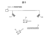
- FIG. BRIEF DESCRIPTION OF THE DRAWINGS It is a figure which shows the structural example of the bird's-eye view image provision system by this embodiment (1st-3rd embodiment).
- the first to third embodiments of the present disclosure will describe information presentation techniques for generating and outputting a bird's-eye topographical image of a construction site.
- Embodiments of the present disclosure will be described below with reference to the accompanying drawings.
- functionally identical elements may be labeled with the same numbers.
- the attached drawings show specific embodiments and examples of implementation in accordance with the principles of the present disclosure, they are for the purpose of understanding the present disclosure, and are by no means intended to limit the interpretation of the present disclosure. not used.
- the embodiments of the present disclosure may be implemented with software running on a general-purpose computer, dedicated hardware, or a combination of software and hardware.
- FIG. 16 is a diagram showing a configuration example of a bird's-eye view image providing system (also referred to as an information providing system) according to this embodiment (including second and third embodiments described later).
- the bird's-eye view image providing system includes a work machine 1 having a communication device, at least one photographing device (camera) 33A to 33B installed at the construction site 31, and a computer (information presentation device), a drone (corresponding to the original topography information acquisition unit 26) for capturing a bird's-eye view image of the original topography of the construction site 31 (topography before the construction materials and the work machine 1 are arranged), and a generated and a communication device 49 .
- This system uses a bird's-eye view image (bird's-eye view image 2 to be described later) captured by a drone (corresponding to the original topography information acquisition unit 26). good too.
- the display unit (display device) 29 is arranged remotely from the computer (information presentation device), but may constitute a part of the computer (information presentation device).
- the computer (information presentation device) may be installed outside the construction site 31 (including a remote location) so that an administrator who is away from the construction site 31 can check the bird's-eye view image. It may be arranged in the cockpit of the machine 1 so that the operator can check the bird's-eye view image (or both).
- the information presentation device may be arranged outside the construction site 31 and only the display section 29 may be installed on the working machine 1 . When the information presentation device and the display unit 29 are arranged separately, they may be configured to communicate with each other via a network as shown in FIG.
- FIG. 1 is a diagram showing a schematic configuration example of a working machine.
- a hydraulic excavator 1 will be described as an example of a working machine.
- the hydraulic excavator 1 is configured by mounting an upper traveling body 15 on a lower traveling body 14 via a turning mechanism 16 .
- the turning mechanism 16 includes a hydraulic motor and turns the upper traveling body 15 clockwise or counterclockwise.
- a boom 8 is attached to the upper traveling body 15 .
- the boom 8 is vertically swung with respect to the upper traveling body 15 by a hydraulically driven boom cylinder 5 .
- An arm 9 is attached to the tip of the boom 8 .
- the arm 9 swings in the front-rear direction with respect to the boom 8 by an arm cylinder 6 that is hydraulically driven.
- a bucket 10 is attached to the tip of the arm 9 .
- the bucket 10 swings with respect to the arm 9 by a hydraulically driven bucket cylinder 7 .
- a cab 2 for accommodating an operator is further mounted on the upper traveling body 15 .
- the boom 8, the arm 9, and the bucket 10 may be collectively referred to as a front work section 23.
- the front working section 23 rotates around the center of rotation 17 together with the upper rotating body 15 .
- the distance from the turning center 17 to the tip of the front working portion 23 varies by swinging the boom 8, the arm 9, and the bucket 10.
- the upper traveling body 15 turns around a turning center 17 and an attachment 18 is attached to the upper traveling body 15 .
- the boom 8 swings up and down around a swing center parallel to the y-axis.
- An arm 9 is attached to the tip of the boom 8
- a bucket 10 is attached to the tip of the arm 9 .
- the vehicle body position detection unit 44 uses a device such as GNSS that can acquire its own position, and the vehicle body azimuth angle calculation unit 43 calculates the vehicle azimuth angle.
- FIG. 2A and 2B are diagrams showing examples of the movable range of the work machine.
- FIG. 2A shows the movable range 24 of the excavator 1.
- FIG. 2B shows the range of motion 19 of wheel loader 36 .
- a movable range 24A related to the front working section 23 of the hydraulic excavator 1 is a reachable range of the front working section 23 when the upper revolving body rotates 360 degrees when the front working section chief takes the longest posture. becomes.
- the movable range 24B of the undercarriage 14 is a range that the vehicle body can reach, for example, in T seconds when the hydraulic excavator 1 travels.
- a movable range obtained by integrating the movable ranges 24 ⁇ /b>A and 24 ⁇ /b>B is defined as a movable range 24 related to the hydraulic excavator 1 .
- the movable range 19 of the wheel loader 36 is the range in which the wheel loader 36 can move in the front-rear direction for T seconds with the steering wheel turned to the left and right to the limit.
- FIG. 3 is a block diagram showing a functional configuration example of the information presentation device according to this embodiment.
- the information presentation device has a current topography information acquisition unit 25 , an original topography information acquisition unit 26 , a bird's-eye view image processing unit 27 , and a display unit (display device) 29 .
- the bird's-eye view image processing unit 27 has a bird's-eye view image synthesizing unit 28 .
- the information presentation device is composed of, for example, a computer, and a processor included in the computer transfers information from a memory (storage device; hereinafter the same) to each processing unit (current topography information acquisition unit, original topography information acquisition unit, overhead image processing unit, etc.).
- the information presentation device may be arranged in the operator's seat of the working machine 1, or may be arranged in a remote location (for example, a management office) separate from the working machine 1 and the photographing device 33. good.
- the current topography is captured by a camera or other imaging device 33 installed at the construction site 31, and when the image of the current topography is received, the current topography information acquiring unit 25 integrates them into a bird's-eye view image (bird's-eye view image 1). It converts and transmits to the bird's-eye view image synthesizing unit 28 .
- the original topography information acquisition unit 26 is a bird's-eye view image captured by a drone, satellite, or the like (overhead image of the original topography of the construction site 31), or an image drawn based on the design drawing (original topography bird's-eye image: bird's-eye image 2 ).
- the bird's-eye image synthesizing unit 28 superimposes the bird's-eye image 1 created based on the current terrain information on the bird's-eye image 2 of the construction site 31 acquired by the original terrain information acquisition unit 26 to synthesize the image.
- the overhead image synthesizing unit 28 transmits the synthesized overhead image (overhead image 3) to the display unit 29 .
- the display unit 29 displays the bird's-eye view image 3 synthesized by the bird's-eye image synthesis unit 28 on a display device such as a monitor possessed by the operator of the hydraulic excavator (working machine) 1, or by the site worker, the construction manager, and the site supervisor. / Or a display terminal such as a smartphone.
- FIG. 4 is a diagram showing an example of the bird's-eye view image 2 acquired by the original landform information acquisition unit 26.
- a site worker takes an image before construction using a device that can take a bird's-eye view image, such as a drone.
- the image of the original landform can also be drawn based on the design drawing.
- a construction site 31 is divided into an inside construction site 31 , an outside construction site 32 , and a fixed obstacle 30 . It should be noted that the division shall be carried out before the start of construction, and it is not necessary to increase the update frequency.
- the classification method must be set by the site worker or the construction manager, but using a learning function such as deep learning, an algorithm that automatically recognizes the boundaries of the fixed obstacles 30 and the construction site 31 can be used. good too.
- the coordinates of the reference point of the construction site 31 are determined at the time of photographing/drawing the bird's-eye view image.
- FIG. 5 is a diagram showing an example of the bird's-eye view image 1 acquired by the current topography information acquisition unit 25.
- At least one photographing device 33 such as a camera is arranged near the construction site 31 or in the construction site 31 at a position and height that can photograph the inside of the construction site 31 . Then, the construction site 31 is photographed by the photographing device 33 .
- the worker manually registers in advance the position (coordinates), height, angle of view, and line-of-sight direction of the imaging device 33, or installs a device capable of self-position estimation such as GNSS and the imaging device 33. is automatically registered in the current topography information acquisition unit 25.
- the current topography information acquisition unit 25 pre-stores (in the above memory) the deformation parameters of the images captured by the image capturing device 33 for each image capturing device 33 .
- the deformation parameter of the image is data that can be specified (determined) based on the installation position and line-of-sight direction of the photographing device 33 .
- the method for generating the bird's-eye view image 1 is not limited to this.
- a three-dimensional image of the construction site 31 is created by performing triangulation on a plurality of images acquired by the current topography information acquisition unit 25, and an overall bird's-eye view image (bird's-eye view image 1) is created based on the three-dimensional image thus obtained. You may create it.
- FIG. 6 is a diagram showing an example of a bird's-eye view image 3 generated by the bird's-eye view image synthesizing unit 28 by superimposing the current landform information (bird's-eye view image 1) on the original landform information (bird's-eye view image 2).
- the bird's-eye view image 1 of the current landform created by the current landform information acquisition unit 25 is compared with the reference point of the original landform information (bird's-eye view image 2) based on the position information of each imaging device 33, and the position to be synthesized is adjusted. generates a bird's-eye view image 3.
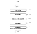
- FIG. 7 is a flowchart for explaining the details of the bird's-eye view image generation process for generating the bird's-eye view image 3 according to this embodiment.
- each processing unit (the current topography information acquisition unit 25, the original topography information acquisition unit 26, the bird's-eye view image synthesizing unit 28) is the main body of operation. Since it is implemented by being read by a processor of a computer (information presentation device) from , the processor may be the main body of operation.
- the original topography information acquisition unit 26 acquires a bird's-eye view image captured by a drone, satellite, or the like, or an image (bird's-eye image 2) drawn based on a design drawing, and transmits the bird's-eye image 2 to the bird's-eye image synthesizing unit 28.
- the bird's-eye view image 2 may be, for example, an image stored in advance in a database or storage device, or may be an image captured or obtained by an operator or construction manager and input to an information presentation device.
- step 102 The current landform information acquisition unit 25 receives an image of the current landform captured by at least one imaging device 33 and transmitted therefrom.
- Step 103 The current terrain information acquisition unit 25 aligns the images (images from the plurality of image capturing devices 33) received in step 102 with a predetermined reference point (for example, any pixel or area of any one image). They are integrated together and converted into a bird's-eye view image (bird's-eye view image 1). Then, the current topography information acquisition unit 25 transmits the generated bird's-eye view image 1 to the bird's-eye view image synthesizing unit 28 .
- a predetermined reference point for example, any pixel or area of any one image.
- Step 104 The overhead image synthesizing unit 28 synthesizes or converts the overhead image 2 received from the original topography information acquisition unit 26 and the overhead image 1 received from the current topography information acquisition unit 25 to generate a synthetic overhead image (overhead image 3). , to the display unit 29 .
- Step 105 The display unit 29 displays the overhead image 3 on the display screen.
- the operator, construction manager, operator of the hydraulic excavator (working machine) 1, surrounding workers, and/or site supervisor can grasp the situation of the construction site from a bird's-eye view.
- the operator, construction manager, operator of the hydraulic excavator (working machine) 1, surrounding workers, and/or site supervisor can grasp the situation of the construction site from a bird's-eye view.
- the second embodiment provides information presentation capable of presenting the blind spot 40 to the operator of the hydraulic excavator (working machine) 1 when there is a blind spot (the blind spot 40 described later) at the construction site 31. It is to provide an apparatus and an information presentation method.
- FIGS. 8 to 11 An information presentation device according to a second embodiment of the present disclosure will be described using FIGS. 8 to 11.
- FIG. 8 to 11 the same reference numerals as those in FIGS. 1 to 7 indicate the same parts or processing units, and thus the description thereof will be omitted.
- the bird's-eye image of the current terrain is superimposed on the bird's-eye image of the original terrain. and a judgment unit 38 for judging that the bird's-eye view image information of the current terrain is insufficient according to the calculated distance to the blind spot 40 and area of the blind spot 40 .
- FIG. 8 is a block diagram showing a functional configuration example of an information presentation device according to the second embodiment.
- the blind spot calculation unit 39 divides the bird's-eye view image 1 into grids based on the bird's-eye view image of the current terrain created by the current terrain information acquisition unit 25 (bird's-eye image 1). Calculate the area of the mass outside the shooting range of .
- the range of the blind spot 40 can be estimated in detail from the position, height, line-of-sight direction, and angle of view of the imaging device 33 .
- the determination unit 38 determines whether or not the information of the bird's-eye view image 1 is insufficient according to the result calculated by the blind spot calculation unit 39 . Specifically, when the area of the blind spot 40 at the construction site 31 exceeds a certain threshold for the area of the entire construction site 31, the determination unit 38 outputs information (for safe operation of the work machine 1 (body) necessary information) is determined to be insufficient. By doing so, for example, when the work machine (hydraulic excavator) 1 works near the blind spot, there is a possibility that an obstacle suddenly appearing from the blind spot 40 of the fixed obstacle 30 will come into contact with the front working part 23 or the counterweight 11. Therefore, it is possible to issue a warning in advance, mainly when turning or traveling.
- the threshold for the area of the blind spot 40 can be arbitrarily set by the construction manager. Further, when the position (coordinates) of the work machine 1 can be estimated using GNSS or the like, the imaging device 33, or the like, the distance between the work machine 1 and the blind spot 40 is equal to or less than a threshold, for example, the movable range of the work machine 1. 24 and the area of the corresponding blind spot 40 is a certain amount or more, it is determined that necessary information (information necessary for safely operating the work machine 1 (vehicle body)) is insufficient. good too.
- the display unit 29 displays a bird's-eye view image 4 (with blind spots added) generated by performing display processing such as filling in blind spots 40 in a bird's-eye image (bird's-eye image 3) obtained by synthesizing the bird's-eye images 1 and 2. a bird's-eye view image). This allows the operator, construction manager, surrounding workers, and/or site supervisor to visualize the blind spot 40 of the construction site 31 . Further, when the determination unit 38 determines that the necessary information is insufficient, the display unit 29 displays a warning such as "insufficient information". In addition to a display device such as a monitor and a display terminal such as a smartphone, the display unit 29 may issue a warning by voice.
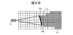
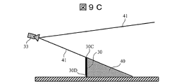
- ⁇ Calculation of blind spot 40> A method of calculating the blind spot 40 (presence or absence of the blind spot, position of the blind spot, width (size) of the blind spot) will be described in detail with reference to FIGS. 9A to 9C.
- the photographing device 33 such as a camera
- the line connecting the ends 30A and 30B of the fixed obstacle 30 and the center point of the photographing device 33 becomes the blind spot line 41.
- the blind spot is 40 on the inside.
- the blind spot 40 is evenly divided into grids or pixel units (the coordinates that make up the blind spot can be specified), so that the area of the blind spot 40 is the area of the number of squares.
- the lattice is determined to be a square forming the blind spot 40 .
- the threshold can be arbitrarily set.
- the photographing device 33 such as a camera
- the line connecting the upper part 30C of the fixed obstacle and the center point of the photographing device 33 becomes the blind spot line 41, and the depth It is possible to reduce the blind spots of the part.
- the blind spot 40 three-dimensionally, it becomes possible to accurately determine whether or not the work machine 1 can be operated safely.
- FIG. 10 is a diagram showing an example of a bird's-eye view image 4 (a bird's-eye view image generated by adding blind spots to the bird's-eye view image 3) according to the second embodiment.
- the display unit 29 displays the bird's-eye view image 4 generated by superimposing the blind spots 40 of the current topography information acquisition unit 25 on the bird's-eye view image 3 on the display screen of the information presentation device.
- the display unit 29 displays “WARNING” on the display screen to warn of the possibility that another obstacle (not shown) will appear from the blind spot 40 .
- FIG. 11 is a flowchart for explaining the details of the process of generating the bird's-eye view image 4 according to the second embodiment.
- each processing unit (the current terrain information acquisition unit 25, the original terrain information acquisition unit 26, the blind spot calculation unit 39, the bird's-eye view image synthesis unit 28, and the determination unit 38) is the main body of operation.
- the processor of the computer information presentation device
- the processor may be the main body of operation.
- Step 201 The original topography information acquisition unit 26 acquires a bird's-eye view image captured by a drone, satellite, or the like, or an image (bird's-eye image 2) drawn based on a design drawing, and transmits the bird's-eye image 2 to the bird's-eye image synthesizing unit 28.
- the bird's-eye view image 2 may be, for example, an image stored in advance in a database or a storage device, or an image captured or obtained by an operator or a construction manager and input to an information presentation device. good too.
- step 202 The current landform information acquisition unit 25 receives an image of the current landform captured by at least one imaging device 33 and transmitted therefrom.
- Step 203 The current terrain information acquisition unit 25 aligns the images (images from the plurality of image capturing devices 33) received in step 202 with predetermined reference points (for example, arbitrary pixels or areas of any one image). They are integrated together and converted into a bird's-eye view image (bird's-eye view image 1). Then, the current topography information acquisition unit 25 transmits the generated bird's-eye view image 1 to the blind spot calculation unit 39 .
- predetermined reference points for example, arbitrary pixels or areas of any one image.
- Blind spot calculation unit 39 determines the presence or absence of blind spot 40 (see FIGS. 9A to 9C), the area of blind spot 40 (see FIGS. 9A to 9C), and the distance to blind spot 40 (distance: for example, of work machines 1A and 1B). The shortest distance from the movable range 24A or the movable range 24 to the blind spot 40) is calculated. The blind spot calculation unit 39 then transmits information (presence, presence, area, and distance) of the blind spots 40 together with the bird's-eye view image 1 to the bird's-eye view image synthesizing unit 28 .
- Step 205 The bird's-eye view image synthesizing unit 28 synthesizes or converts the bird's-eye view image 2 received from the original landform information acquisition unit 26 and the bird's-eye view image 1 received from the blind spot calculation unit 39 (which may be received directly from the current landform information acquisition unit 25). Then, a synthetic bird's-eye view image (bird's-eye view image 3) is generated, and the bird's-eye view image 4 (bird's-eye view image including the blind spot) is generated by synthesizing the bird's-eye view image 3 with the blind spot 40 received from the blind spot calculation unit 39 .
- a synthetic bird's-eye view image (bird's-eye view image 3) is generated
- the bird's-eye view image 4 birds's-eye view image including the blind spot) is generated by synthesizing the bird's-eye view image 3 with the blind spot 40 received from the blind spot calculation unit 39 .
- the bird's-eye view image synthesizing unit 28 transmits information on the bird's-eye view image 4 and the blind spot 40 (for example, at least the area of the blind spot among the presence or absence of the blind spot, the area, and the distance) to the determination unit 38 .
- step 206 Based on the information received from the bird's-eye view image synthesizing unit 28, the determination unit 38 determines whether necessary information (information necessary for safely operating the work machine 1 (body)) has been acquired. For example, the distance from work machine 1 to blind spot 40 (shortest distance from movable range 24A of working machines 1A and 1B or movable range 24 to blind spot 40) is greater than a predetermined threshold (distance threshold), and the area of blind spot 40 is If it is equal to or less than the predetermined threshold, it is determined that the necessary information has been acquired. If it is determined that the necessary information has been acquired (Yes in step 206), the process proceeds to step 207. If it is determined that the necessary information has not been obtained (No in step 206), the process proceeds to step 208.
- a predetermined threshold distance threshold
- step 207 The display unit 29 displays the overhead image 4 on the display screen.
- the construction manager, the operator of the hydraulic excavator (work machine) 1, the surrounding workers, and/or the site supervisor can grasp the situation of the construction site from a bird's-eye view, and the work machine 1 at the construction site 31 can be It is possible to operate safely.
- Step 208 The display unit 29 superimposes a "warning” (such as a word “warning” or a mark for notifying danger) on the bird's-eye view image 4 and displays it on the display screen.
- a "warning” such as a word “warning” or a mark for notifying danger
- the construction manager, the operator of the hydraulic excavator (work machine) 1, surrounding workers, and/or the site supervisor can grasp the situation of the construction site from a bird's-eye view. It is possible to grasp the danger of maneuvering.
- FIG. 12 to 15 the same reference numerals as those in FIGS. 1 to 11 denote the same parts or processing units, and thus the description thereof will be omitted.
- the photographing device 33 is arranged around the construction site 31, and it is determined whether or not necessary information is lacking from the area of the blind spot 40 in the acquired current terrain, and the operator and surrounding workers and warned the foreman.
- data of an in-vehicle bird's-eye view image 48 created based on an image captured by an in-vehicle imaging device 33 is synthesized (overlaid) with the current topography information (bird's-eye view image 1) so that the blind spot 40 can be detected. It has the function of reducing the area.
- FIG. 12 is a block diagram showing a functional configuration example of an information presentation device according to the third embodiment.
- the information presentation device includes, in addition to the components shown in FIG. , is equipped with
- the vehicle body azimuth angle calculation unit 43 acquires the azimuth of the work machine 1 on the construction site basis based on the position information from the vehicle body position detection unit 44, and transmits the information on the azimuth to the in-vehicle bird's-eye view image correction unit 46. Further, the vehicle body position detection unit 44 identifies the position of the work machine 1 based on the construction site basis or the global coordinate basis, and transmits information on the position to the in-vehicle bird's-eye view image correction unit 46 .
- the in-vehicle bird's-eye image creating unit 45 transmits a bird's-eye image created based on the vehicle-mounted imaging device 33 (hereinafter referred to as an in-vehicle bird's-eye image 48 ) to the in-vehicle bird's-eye image correction unit 46 .
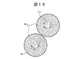
- FIG. 13 is a diagram showing an example of the in-vehicle bird's-eye view image 48.
- the vehicle-mounted bird's-eye view image 48 is synthesized with the bird's-eye view image of the current landform at different positions and directions depending on the position and orientation of the work machine 20 . Therefore, first, from the positional relationship between the position information of the work machines 1A and 1B and the reference point of the construction site 31, the position where the in-vehicle bird's-eye view image 48 is synthesized is specified.
- the vehicle-mounted bird's-eye view image correction unit 46 rotates the image data by the azimuth angle of the work machines. Furthermore, by projecting the rotated image data onto a bird's-eye view image according to the positions of the acquired work machines 1A and 1B and synthesizing them, it is possible to display the vehicle-mounted bird's-eye view image 48 on the bird's-eye view image of the construction site.
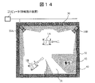
- FIG. 14 is a diagram showing an example of a synthesized bird's-eye view image 5 according to the third embodiment.
- the bird's-eye view image 5 shown in FIG. 14 is an image obtained by reflecting the vehicle-mounted bird's-eye image 48 on the bird's-eye image 1 and synthesizing it with the bird's-eye view image 2: the vehicle-mounted bird's-eye image 48 covers the blind spot 40 of the bird's-eye image 4 shown in FIG. It is an image with the area removed.
- the bird's-eye view image synthesizing unit 28 further superimposes the bird's-eye view image 2 from the original topography information acquisition unit 26 on the bird's-eye view image (the image obtained by superimposing the blind spot 40 and the in-vehicle bird's-eye image 48 on the bird's-eye image 1) from the blind spot calculation unit 39. By doing so, the bird's-eye view image 5 can be generated.
- the display switching unit 47 can switch between the in-vehicle bird's-eye view image 48 and the bird's-eye view image 5 (surroundings bird's-eye view image) using a button or the touch screen of the monitor.
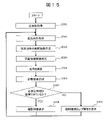
- FIG. 15 is a flowchart for explaining the details of the process of generating the bird's-eye view image 5 according to the third embodiment.
- each processing unit current topography information acquisition unit 25, original topography information acquisition unit 26, blind spot calculation unit 39, overhead image synthesis unit 28, determination unit 38, vehicle azimuth angle calculation unit, vehicle position detection unit 44, in-vehicle bird's-eye view image creation unit 45, and display switching unit 47
- the processor may be the main body of operation.
- Step 301 The original topography information acquisition unit 26 acquires a bird's-eye view image captured by a drone, satellite, or the like, or an image (bird's-eye image 2) drawn based on a design drawing, and transmits the bird's-eye image 2 to the bird's-eye image synthesizing unit 28.
- the bird's-eye view image 2 may be, for example, an image stored in advance in a database or a storage device, or an image captured or obtained by an operator or a construction manager and input to an information presentation device. good too.
- step 302 The current landform information acquisition unit 25 receives an image of the current landform captured by at least one imaging device 33 and transmitted therefrom.
- Step 303 The current topography information acquisition unit 25 aligns the images received in step 302 (images from the plurality of photographing devices 33) to a predetermined reference point (for example, any pixel or area of any one image). They are integrated together and converted into a bird's-eye view image (bird's-eye view image 1). Then, the current topography information acquisition unit 25 transmits the generated bird's-eye view image 1 to the blind spot calculation unit 39 .
- a predetermined reference point for example, any pixel or area of any one image.
- Step 304 The in-vehicle bird's-eye view image correction unit 46 receives the in-vehicle bird's-eye view image of the work machine 1 from the in-vehicle bird's-eye image creation unit 45 , the information on the azimuth angle of the work machine 1 from the vehicle body azimuth angle calculation unit 43 , and the work machine 1 from the vehicle body position detection unit 44 . Get the position information of each. Then, the vehicle-mounted bird's-eye image correction unit 46 corrects the vehicle-mounted bird's-eye image of the work machine 1 based on the information on the azimuth angle and position of the work machine 1, and transmits the corrected vehicle-mounted bird's-eye image to the bird's-eye image synthesizing unit 28. .
- the blind spot calculator 39 determines the presence or absence of the blind spot 40 (see FIGS. 9A to 9C), the area of the blind spot 40 (see FIGS. 9A to 9C), and the distance to the blind spot 40 (distance: for example, working machines 1A and 1B). or the shortest distance from the movable range 24 to the blind spot 40).
- the blind spot calculation unit 39 then transmits information (presence, presence, area, and distance) of the blind spots 40 together with the bird's-eye view image 1 to the bird's-eye view image synthesizing unit 28 .
- step 306 The bird's-eye view image synthesizing unit 28 receives the bird's-eye view image 2 received from the original topography information acquisition unit 26, the bird's-eye view image 1 and information on the blind spot 40 received from the blind spot calculation unit 39, and the vehicle-mounted bird's-eye image received from the vehicle-mounted bird's-eye image correction unit 46. Based on (corrected in-vehicle overhead image) 48 (combining these), overhead image 5 (see FIG. 14) reflecting blind spot 40 and in-vehicle overhead image is generated. Then, the bird's-eye view image synthesizing unit 28 transmits the bird's-eye view image 5 to the determination unit 38 .
- step 307 Based on the information received from the bird's-eye view image synthesizing unit 28, the determination unit 38 determines whether necessary information (information necessary for safely operating the work machine 1 (body)) has been acquired. For example, the distance from work machine 1 to blind spot 40 (shortest distance from movable range 24A of working machines 1A and 1B or movable range 24 to blind spot 40) is greater than a predetermined threshold (distance threshold), and the area of blind spot 40 is If it is equal to or less than the predetermined threshold, it is determined that the necessary information has been obtained. If it is determined that the necessary information has been acquired (Yes in step 307), the process proceeds to step 308. If it is determined that the necessary information has not been obtained (No in step 307), the process proceeds to step 309.
- necessary information information necessary for safely operating the work machine 1 (body)
- Step 308 The display unit 29 displays the overhead image 5 on the display screen.
- the construction manager, the operator of the hydraulic excavator (work machine) 1, the surrounding workers, and/or the site supervisor can grasp the situation of the construction site from a bird's-eye view, and the work machine 1 at the construction site 31 can be It is possible to operate safely.
- Step 309 The display unit 29 superimposes a "warning” (such as a word “warning” or a mark for notifying danger) on the bird's-eye view image 5 and displays it on the display screen.
- a "warning” such as a word “warning” or a mark for notifying danger
- the construction manager, the operator of the hydraulic excavator (work machine) 1, surrounding workers, and/or the site supervisor can grasp the situation of the construction site from a bird's-eye view. It is possible to grasp the danger of maneuvering.
- the information presentation device includes a first bird's-eye view image (bird's-eye view image 1) that provides a bird's-eye view of the current topography of the construction site 31, and A first synthetic bird's-eye view image obtained by superimposing a second bird's-eye view image (bird's-eye view image 2) that represents a bird's-eye view of the original topography of the construction site acquired by a method other than photography by the device 33 (for example, photography by a drone or satellite).
- bird's-eye view image 3 is generated and output (displayed on the display screen of the display unit 29).
- the bird's-eye view image 2 that originally exists in the current situation image acquired by the photographing device is used complementarily to generate the bird's-eye view image of the entire current construction site.
- a worker can be provided with a useful bird's-eye view image of a construction site.
- the information presentation device uses the first bird's-eye view image (bird's-eye view image 1) acquired by the imaging device 33 to identify the blind spot 40 at the construction site, and the image of the blind spot 40 is reflected in the first synthetic bird's-eye image (bird's-eye image 3) to generate and output a second synthetic bird's-eye image (bird's-eye image 4).
- the possibility that another work machine or the like may come out of the blind spot 40 can be grasped from a bird's-eye view, so that the work machine can be operated safely.
- the information presentation device converts the vehicle-mounted bird's-eye image generated based on the image captured by the vehicle-mounted camera installed on the work machine 1 into the second synthesized bird's-eye image (bird's-eye image 4). ) to generate and output a third synthesized bird's-eye view image (bird's-eye view image 5).
- the area of the blind spot 40 can be reduced, and the work machine can be operated more safely.
- the functionality of the embodiments of the present disclosure can also be implemented by software program code.
- a storage medium recording the program code is provided to the system or device, and the computer (or CPU or MPU) of the system or device reads the program code stored in the storage medium.
- the program code itself read from the storage medium implements the functions of the above-described embodiments, and the program code itself and the storage medium storing it constitute the present disclosure.
- Storage media for supplying such program code include, for example, flexible disks, CD-ROMs, DVD-ROMs, hard disks, optical disks, magneto-optical disks, CD-Rs, magnetic tapes, non-volatile memory cards, and ROMs. etc. are used.
- the OS operating system
- the processing implements the functions of the above-described embodiments.
- the CPU of the computer performs part or all of the actual processing based on the instructions of the program code. may implement the functions of the above-described embodiment.
- the program code of the software that realizes the functions of the embodiment can be transferred to storage means such as the hard disk and memory of the system or device, or storage media such as CD-RW and CD-R.
- storage means such as the hard disk and memory of the system or device, or storage media such as CD-RW and CD-R.
- the computer (or CPU or MPU) of the system or device may read and execute the program code stored in the storage means or the storage medium at the time of use.
- control lines and information lines indicate those that are considered necessary for explanation, and not all the control lines and information lines are necessarily indicated on the product. All configurations may be interconnected.
Landscapes
- Engineering & Computer Science (AREA)
- Civil Engineering (AREA)
- Structural Engineering (AREA)
- General Engineering & Computer Science (AREA)
- Mining & Mineral Resources (AREA)
- Physics & Mathematics (AREA)
- Theoretical Computer Science (AREA)
- General Physics & Mathematics (AREA)
- Multimedia (AREA)
- Component Parts Of Construction Machinery (AREA)
- Image Processing (AREA)
- Closed-Circuit Television Systems (AREA)
- Computer Vision & Pattern Recognition (AREA)
- Geometry (AREA)
- Signal Processing (AREA)
- Image Analysis (AREA)
Abstract
Priority Applications (5)
| Application Number | Priority Date | Filing Date | Title |
|---|---|---|---|
| JP2023508644A JP7461567B2 (ja) | 2021-03-25 | 2022-01-06 | 情報提示装置 |
| US18/023,460 US12366055B2 (en) | 2021-03-25 | 2022-01-06 | Information presentation device |
| KR1020237006763A KR102796800B1 (ko) | 2021-03-25 | 2022-01-06 | 정보 제시 장치 |
| CN202280005809.6A CN115989521A (zh) | 2021-03-25 | 2022-01-06 | 信息提示装置 |
| EP22774540.3A EP4187487B1 (fr) | 2021-03-25 | 2022-01-06 | Dispositif de présentation d'informations |
Applications Claiming Priority (2)
| Application Number | Priority Date | Filing Date | Title |
|---|---|---|---|
| JP2021052234 | 2021-03-25 | ||
| JP2021-052234 | 2021-03-25 |
Publications (1)
| Publication Number | Publication Date |
|---|---|
| WO2022201735A1 true WO2022201735A1 (fr) | 2022-09-29 |
Family
ID=83396749
Family Applications (1)
| Application Number | Title | Priority Date | Filing Date |
|---|---|---|---|
| PCT/JP2022/000208 Ceased WO2022201735A1 (fr) | 2021-03-25 | 2022-01-06 | Dispositif de présentation d'informations |
Country Status (6)
| Country | Link |
|---|---|
| US (1) | US12366055B2 (fr) |
| EP (1) | EP4187487B1 (fr) |
| JP (1) | JP7461567B2 (fr) |
| KR (1) | KR102796800B1 (fr) |
| CN (1) | CN115989521A (fr) |
| WO (1) | WO2022201735A1 (fr) |
Cited By (1)
| Publication number | Priority date | Publication date | Assignee | Title |
|---|---|---|---|---|
| US20250014350A1 (en) * | 2022-04-05 | 2025-01-09 | Honeywell International Inc. | Workspace operating condition detection apparatus for use with a fall protection device and methods of using the same |
Citations (4)
| Publication number | Priority date | Publication date | Assignee | Title |
|---|---|---|---|---|
| JP2016181119A (ja) * | 2015-03-24 | 2016-10-13 | 株式会社フジタ | 移動機器の周囲状況提示システム |
| WO2017187764A1 (fr) * | 2016-04-28 | 2017-11-02 | ソニー株式会社 | Dispositif terminal de traitement d'informations et dispositif de distribution |
| JP2019151968A (ja) | 2018-02-28 | 2019-09-12 | 株式会社小松製作所 | 情報提示装置および情報提示方法 |
| JP2020057981A (ja) * | 2018-10-04 | 2020-04-09 | クラリオン株式会社 | 画像作成システム、画像作成装置、及び画像作成装置の制御方法 |
Family Cites Families (8)
| Publication number | Priority date | Publication date | Assignee | Title |
|---|---|---|---|---|
| JP4847913B2 (ja) * | 2007-03-30 | 2011-12-28 | 日立建機株式会社 | 作業機械周辺監視装置 |
| JP2010089632A (ja) * | 2008-10-08 | 2010-04-22 | Caterpillar Japan Ltd | 監視対象領域表示システム |
| JP6375633B2 (ja) * | 2014-02-12 | 2018-08-22 | 株式会社デンソー | 車両周辺画像表示装置、車両周辺画像表示方法 |
| JP6204884B2 (ja) * | 2014-07-25 | 2017-09-27 | 日立建機株式会社 | 旋回式作業機の周囲表示装置 |
| JP2016225865A (ja) * | 2015-06-01 | 2016-12-28 | 東芝アルパイン・オートモティブテクノロジー株式会社 | 俯瞰画像生成装置 |
| JP6464952B2 (ja) * | 2015-08-04 | 2019-02-06 | 株式会社デンソー | 表示制御装置、表示制御プログラム及び表示制御方法 |
| US11153503B1 (en) * | 2018-04-26 | 2021-10-19 | AI Incorporated | Method and apparatus for overexposing images captured by drones |
| CN109920048A (zh) * | 2019-02-15 | 2019-06-21 | 北京清瞳时代科技有限公司 | 监控画面生成方法及装置 |
-
2022
- 2022-01-06 US US18/023,460 patent/US12366055B2/en active Active
- 2022-01-06 CN CN202280005809.6A patent/CN115989521A/zh active Pending
- 2022-01-06 JP JP2023508644A patent/JP7461567B2/ja active Active
- 2022-01-06 WO PCT/JP2022/000208 patent/WO2022201735A1/fr not_active Ceased
- 2022-01-06 KR KR1020237006763A patent/KR102796800B1/ko active Active
- 2022-01-06 EP EP22774540.3A patent/EP4187487B1/fr active Active
Patent Citations (4)
| Publication number | Priority date | Publication date | Assignee | Title |
|---|---|---|---|---|
| JP2016181119A (ja) * | 2015-03-24 | 2016-10-13 | 株式会社フジタ | 移動機器の周囲状況提示システム |
| WO2017187764A1 (fr) * | 2016-04-28 | 2017-11-02 | ソニー株式会社 | Dispositif terminal de traitement d'informations et dispositif de distribution |
| JP2019151968A (ja) | 2018-02-28 | 2019-09-12 | 株式会社小松製作所 | 情報提示装置および情報提示方法 |
| JP2020057981A (ja) * | 2018-10-04 | 2020-04-09 | クラリオン株式会社 | 画像作成システム、画像作成装置、及び画像作成装置の制御方法 |
Non-Patent Citations (1)
| Title |
|---|
| See also references of EP4187487A4 |
Cited By (2)
| Publication number | Priority date | Publication date | Assignee | Title |
|---|---|---|---|---|
| US20250014350A1 (en) * | 2022-04-05 | 2025-01-09 | Honeywell International Inc. | Workspace operating condition detection apparatus for use with a fall protection device and methods of using the same |
| US12518540B2 (en) * | 2022-04-05 | 2026-01-06 | Honeywell Safety Products Usa, Inc. | Workspace operating condition detection apparatus for use with a fall protection device and methods of using the same |
Also Published As
| Publication number | Publication date |
|---|---|
| EP4187487A1 (fr) | 2023-05-31 |
| CN115989521A (zh) | 2023-04-18 |
| KR20230043968A (ko) | 2023-03-31 |
| US12366055B2 (en) | 2025-07-22 |
| JPWO2022201735A1 (fr) | 2022-09-29 |
| EP4187487B1 (fr) | 2025-10-15 |
| US20230235539A1 (en) | 2023-07-27 |
| EP4187487A4 (fr) | 2024-08-21 |
| JP7461567B2 (ja) | 2024-04-03 |
| KR102796800B1 (ko) | 2025-04-16 |
Similar Documents
| Publication | Publication Date | Title |
|---|---|---|
| JP7285051B2 (ja) | 表示制御装置、および表示制御方法 | |
| JP6243926B2 (ja) | 車両走行システム、搬送車の停車姿勢設定装置が実行する方法、及び搬送車の停車姿勢設定装置 | |
| JP7372029B2 (ja) | 表示制御装置、表示制御システムおよび表示制御方法 | |
| JP6456173B2 (ja) | 車体外部移動物体検知装置 | |
| JP7797546B2 (ja) | 表示制御システムおよび表示制御方法 | |
| JP7458155B2 (ja) | 表示システム、遠隔操作システム、及び表示方法 | |
| JPWO2018043299A1 (ja) | 作業機械の画像表示システム、作業機械の遠隔操作システム、作業機械及び作業機械の画像表示方法 | |
| WO2019012992A1 (fr) | Dispositif et procédé de commande d'affichage, programme et système d'affichage | |
| JP2020117982A (ja) | 作業機械 | |
| JP2021056543A (ja) | 容器計測システム | |
| WO2019167726A1 (fr) | Dispositif et procédé de présentation d'informations | |
| JP2024052764A (ja) | 表示制御装置及び表示方法 | |
| JP7552494B2 (ja) | 施工支援システムおよび施工支援方法 | |
| WO2022201735A1 (fr) | Dispositif de présentation d'informations | |
| JP2023014767A (ja) | 掘削機械の稼働範囲設定システムおよびその制御方法 | |
| WO2021256528A1 (fr) | Dispositif d'étalonnage et procédé d'étalonnage | |
| JP2024093731A (ja) | 作業機械の表示装置及び作業機械 | |
| JP7536580B2 (ja) | 表示制御装置及び表示方法 | |
| JP2022026596A (ja) | 作業機械および施工支援システム | |
| JP2024057361A (ja) | 作業支援装置および作業支援方法 | |
| JP7729544B2 (ja) | 俯瞰映像提示システム | |
| CN118614057A (zh) | 远程操作支援系统和远程操作支援方法 | |
| JP2022129500A (ja) | 地形情報管理システムおよび作業機械 | |
| JP2022150641A (ja) | 物体認識システム | |
| JP2026007523A (ja) | 作業支援装置、作業支援システム、作業機械、遠隔操作装置、プログラムおよび作業支援方法 |
Legal Events
| Date | Code | Title | Description |
|---|---|---|---|
| 121 | Ep: the epo has been informed by wipo that ep was designated in this application |
Ref document number: 22774540 Country of ref document: EP Kind code of ref document: A1 |
|
| ENP | Entry into the national phase |
Ref document number: 2023508644 Country of ref document: JP Kind code of ref document: A |
|
| ENP | Entry into the national phase |
Ref document number: 20237006763 Country of ref document: KR Kind code of ref document: A |
|
| ENP | Entry into the national phase |
Ref document number: 2022774540 Country of ref document: EP Effective date: 20230223 |
|
| NENP | Non-entry into the national phase |
Ref country code: DE |
|
| WWG | Wipo information: grant in national office |
Ref document number: 2022774540 Country of ref document: EP |