WO2017187796A1 - Dispositif de redressement pour véhicule - Google Patents
Dispositif de redressement pour véhicule Download PDFInfo
- Publication number
- WO2017187796A1 WO2017187796A1 PCT/JP2017/008933 JP2017008933W WO2017187796A1 WO 2017187796 A1 WO2017187796 A1 WO 2017187796A1 JP 2017008933 W JP2017008933 W JP 2017008933W WO 2017187796 A1 WO2017187796 A1 WO 2017187796A1
- Authority
- WO
- WIPO (PCT)
- Prior art keywords
- opening
- vehicle
- rectifier
- area
- traveling wind
- Prior art date
- Legal status (The legal status is an assumption and is not a legal conclusion. Google has not performed a legal analysis and makes no representation as to the accuracy of the status listed.)
- Ceased
Links
Images



Classifications
-
- B—PERFORMING OPERATIONS; TRANSPORTING
- B60—VEHICLES IN GENERAL
- B60R—VEHICLES, VEHICLE FITTINGS, OR VEHICLE PARTS, NOT OTHERWISE PROVIDED FOR
- B60R3/00—Arrangements of steps or ladders facilitating access to or on the vehicle, e.g. running-boards
-
- B—PERFORMING OPERATIONS; TRANSPORTING
- B60—VEHICLES IN GENERAL
- B60R—VEHICLES, VEHICLE FITTINGS, OR VEHICLE PARTS, NOT OTHERWISE PROVIDED FOR
- B60R19/00—Wheel guards; Radiator guards, e.g. grilles; Obstruction removers; Fittings damping bouncing force in collisions
- B60R19/02—Bumpers, i.e. impact receiving or absorbing members for protecting vehicles or fending off blows from other vehicles or objects
- B60R19/48—Bumpers, i.e. impact receiving or absorbing members for protecting vehicles or fending off blows from other vehicles or objects combined with, or convertible into, other devices or objects, e.g. bumpers combined with road brushes, bumpers convertible into beds
Definitions
- the present disclosure relates to a rectifier mounted on a vehicle such as a truck having a step for getting on and off under a door of a cab.
- Patent Literature 1 discloses an example of a boarding / alighting step provided below a side door provided on both side surfaces of a cab.
- the step for getting on and off as in Patent Document 1 is typically provided as a recessed region formed so as to be recessed inward with respect to the side surface of the cab. Since such a hollow region is exposed to the outside, the traveling wind received from the front of the vehicle during traveling intrudes to generate a vortex (reverse flow) of airflow around the step for getting on and off to increase the traveling resistance. It becomes a factor.
- Such running resistance generally increases in proportion to the square of the vehicle speed, and thus is easily affected by high-speed running. For example, large trucks used for long-distance transportation often travel at high speeds centering on highways, and therefore it is desired to reduce travel resistance due to steps for getting on and off.
- At least one embodiment of the present invention has been made in view of the above circumstances, and an object thereof is to provide a vehicle rectifier capable of reducing running resistance with a simple structure.
- a vehicle rectifier is a vehicle rectifier having a step for getting on and off provided below a cab door, wherein the cab and / or Alternatively, a first opening that opens toward the front of the vehicle in the bumper and into which traveling wind is introduced during traveling, a recessed region that forms the step for getting on and off in the vehicle, and / or a vehicle width direction of the recessed region A second opening that is opened so that the traveling wind introduced from the first opening is blown into a lateral region that is on the outside; and a connection path that communicates between the first opening and the second opening.
- part of the traveling wind received by the vehicle from the front during traveling is taken in by the first opening.
- the traveling wind taken into the first opening is guided to the second opening through the connection path and blown into the depression area and / or the side area, so that the traveling wind tries to enter the depression area from the side of the vehicle.
- Shut off running wind As a result, it is possible to effectively prevent the running resistance from increasing due to the running wind entering the recessed area from the outside. Since such a rectifier does not require a structure such as an opening / closing mechanism, the running resistance can be reduced with a simple structure.
- the second opening is configured such that the traveling wind blown from the second opening is a front surface of the cab and a midpoint in the front-rear direction of the hollow region. It opens so that it may pass through the area
- the second opening is configured such that the traveling wind introduced from the first opening covers at least partially the depression area. Open to blow out.
- a so-called air curtain is formed that covers the depression area with the traveling wind blown out from the second opening, thereby blocking the traveling wind that tries to enter the depression area from the outside during traveling. Is done. As a result, the traveling wind that tries to enter the recessed area from the outside is blocked by the air curtain and prevented from entering the recessed area, so that the traveling resistance is effectively reduced.
- the second opening is provided in front of an intermediate point in the front-rear direction of the depression region, and the first opening The running wind that is introduced from is opened so as to blow out rearward without interfering with the hollow region.
- an air curtain can be formed by a stable air flow by running air from the second opening toward the rear without interfering with the recessed area.
- the second opening is provided on the inner wall in the front half of the recessed area.
- the second opening is provided on the inner wall in the front half of the depression area, so that the traveling wind from the second opening passes through the side area from the depression area, and the vehicle
- the air curtain can be formed so as to be blown rearward and at least partially cover the recessed area.
- the second opening is provided in front of the depression region on the side surface of the vehicle.
- the air curtain is at least partially covered by the traveling wind blown out from the second opening during traveling by the traveling wind received from the front so as to at least partially cover the recessed area. It is formed.
- the traveling wind from the second opening is blown out from the side of the vehicle toward the outside in the vehicle width direction, the direction of the traveling wind blown out from the second opening is not finely designed, The above effects can be obtained. Therefore, it is easy to design and can be realized at a low manufacturing cost.
- the second opening is formed from an upper inner wall of the recess region or the recess region of the side surface of the vehicle. From the upper side, the running wind introduced from the first opening portion is opened so as to blow out downward without interfering with the hollow region.
- the traveling wind from the second opening blows from the upper side to the lower side of the recessed area, thereby forming an air curtain so as to at least partially cover the recessed area.
- Running resistance can be reduced.
- the opening direction of the second opening is downward, it is possible to prevent foreign matters such as rainwater from entering the second opening.
- the second opening is formed from a lower inner wall of the recess region or from the recess region of the side surface of the vehicle. From the lower side, the opening is made so that the traveling wind introduced from the first opening blows upward without interfering with the recessed region.
- the running wind from the second opening blows out from the lower side to the upper side of the recessed area, thereby forming an air curtain so as to at least partially cover the recessed area.
- Running resistance can be reduced.
- down force is obtained as the reaction force of the traveling wind blown upward from the second opening, so that the traveling resistance can be reduced while improving the traveling stability of the vehicle.
- the second opening portion causes the traveling wind introduced from the first opening portion to blow out toward the inner wall of the hollow region. Open to.
- the traveling wind blown from the second opening forms a turbulent flow in the recessed area by colliding with the inner wall of the recessed area.
- the turbulent flow formed in the depression area in this way prevents the traveling wind from entering the depression area from the outside, so that the running resistance can be prevented from increasing.
- FIG. 1 is a perspective view showing a basic configuration of a vehicle 1 including a rectifier according to at least one embodiment of the present invention. It is a schematic diagram which shows the flow path of the driving
- FIG. 8 is a vertical cross-sectional view passing through the recessed area in FIG. 7. It is a schematic diagram which shows perspectively the flow path of the driving
- FIG. 10 is a vertical cross-sectional view passing through the recessed area of FIG. 9. It is a modification of FIG.
- expressions representing shapes such as quadrangular shapes and cylindrical shapes not only represent shapes such as quadrangular shapes and cylindrical shapes in a strict geometric sense, but also within the range where the same effect can be obtained. A shape including a chamfered portion or the like is also expressed.
- the expressions “comprising”, “comprising”, “comprising”, “including”, or “having” one constituent element are not exclusive expressions for excluding the existence of the other constituent elements.
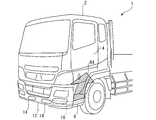
- FIG. 1 is a perspective view showing a basic configuration of a vehicle 1 including a rectifier according to at least one embodiment of the present invention.
- the vehicle 1 is a truck vehicle in which a cab 2 and the like are arranged on a chassis (not shown) on which a power train including a power source such as an internal combustion engine is mounted.
- the cab 2 is mounted on a chassis via a cab suspension (not shown), and side doors 4 that can be opened and closed when a passenger gets on and off are provided on both sides in the vehicle width direction.
- a step for getting on and off (hereinafter referred to as “step” as appropriate) 6 is provided below the side door 4 so that an occupant can get into the cab 2 when getting on and off. ing.
- This step 6 is mounted on the chassis side, and is arranged so that a predetermined gap 8 is formed between the upper side door 4.
- the step 8 on the chassis side is displaced relative to the side door 4 during traveling, so that the size of the gap 8 is also increased. It also changes.
- the size of the gap 8 when the vehicle is stopped is larger than the maximum displacement amount of the side door 4 with respect to the chassis side, and is designed in advance so as not to cause physical interference with the step 6 during traveling.
- Step 6 is provided in a recessed region 10 formed in a concave shape toward the inner side in the vehicle width direction with respect to the surface of the side door 4.
- the hollow region 10 is formed in a substantially rectangular parallelepiped space, and the step 6 is attached to the chassis side so as to constitute the lower surface side of the hollow region 10.
- the occupant can get on and off by inserting his / her toes on the toe side into the indented region 10 and placing the sole on step 6.
- Such step 6 is formed of a material such as metal or resin so as to have sufficient strength to withstand when the weight of the occupant is applied when getting on and off.
- step 6 consists of the plate-shaped member attached to the horizontal direction where a passenger
- Bumper member 12 attached to the chassis side is disposed below the front side of cab 2.
- the bumper member 12 has a longitudinal shape along the vehicle width direction.
- the bumper member 12 is an exterior member having a buffering function.
- various materials such as a metal material such as iron and aluminum and a resin material such as polypropylene, FRP, and carbon fiber are used.
- the surface of the bumper member 12 may be processed by plating or painting.
- FIG. 2 is a schematic view showing a traveling wind flow path R1 formed by the rectifier according to the first embodiment in perspective with the appearance of the vehicle 1
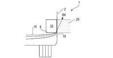
- FIG. 3 is a horizontal sectional view passing through the hollow region 10 of FIG. It is.
- the bumper member 12 of the vehicle 1 is provided with a first opening 14 that opens forward.
- the 1st opening part 14 is opened so that the plate-shaped member which comprises the bumper member 12 may be penetrated, and the traveling wind received from the front at the time of driving
- two first openings 14 are provided symmetrically on the front surface of the bumper member 12. In the following description, one of the two first openings 14 will be described in detail, but unless otherwise specified, both are treated as having the same configuration.
- the bumper member 12 is provided with a coupling path 16 so as to be connected to the first opening 14 from the inside.
- connection path 16 is configured as a hollow member that is configured so that traveling air taken in from the first opening 14 can pass therethrough (for example, the connection path 16 is at least partially closed).
- Such a hollow member is easy to route the interior of the vehicle body so that the second opening 18 is at an appropriate position in order to construct a wind guide path for obtaining a rectifying action, and the rectifying device can be arranged with an efficient layout. realizable.
- connection path 16 route 16 formed so that the inside of the bumper member 12 might be penetrated.
- the traveling wind taken from the first opening portion 14 during traveling is guided to the second opening portion 18 along the connection path 16 as shown in FIG.
- the connection path 16 has the largest cross-sectional area on the first opening 14 side, and is formed so as to gradually narrow toward the back side of the connection path 16.
- the traveling wind can be taken in efficiently, and the flow velocity of the traveling wind taken in from the first opening 14 is reduced by the connection path 16 becoming narrower gradually. This is enhanced by the so-called Venturi effect.
- a stable air curtain is formed by the traveling air blown out from the second opening 18, and an increase in traveling resistance can be prevented.
- connection path 16 is connected to the second opening 18 formed in the hollow region 10 (that is, the connection path 16 is formed to communicate the first opening 14 and the second opening 18).
- the second opening 18 is opened so that the traveling wind introduced from the first opening 14 is blown into the hollow region 10.
- the second opening 18 is designed so that the traveling air blown out from the second opening 18 during traveling blows out so as to at least partially cover the indented region 10 as shown by the flow path R1 in FIG. 3, for example. Has been.
- the flow path R1 of FIG. 3 schematically shows a flow path of traveling air blown out from the second opening 18 in the vehicle 1 traveling at a predetermined speed.
- the predetermined speed may be arbitrary, but is preferably set based on a speed region that is assumed to be frequently used in the vehicle 1. For example, in the case of a large truck that has many opportunities to travel at a constant speed on an expressway, it may be set so as to correspond to an assumed cruise speed.
- the traveling wind that forms the flow path R ⁇ b> 1 is blown out toward the rear of the vehicle after passing through the recessed area 10.
- the traveling wind that tries to enter the hollow region 10 from the outside in the vehicle width direction during traveling is blocked by the traveling wind that blows out from the second opening 18, and the increase in traveling resistance is suppressed. That is, an air curtain that at least partially covers the recessed area 10 is formed by the traveling wind blown from the second opening 18, and traveling air from the outside to the recessed area 10 is prevented.
- the traveling wind from the second opening 18 is blown out without interfering with the inner wall that defines the recessed area 10, so that an air curtain can be formed with a stable airflow.
- the second opening 18 opens so that the flow path R1 passes through the recessed region 10 and / or the side region 20 outside the recessed region 10 in the vehicle width direction, and preferably the front surface 2a of the cab 2 and the recessed region. It opens so that it may pass through the area
- the second opening 18 is provided inside the recessed region 10, so that the traveling wind from the second opening 18 passes through the recessed region 10 and / or the side region 20.
- the second opening 18 is provided on the side surface of the vehicle, so that it passes through only the side region 20 and blows toward the rear of the vehicle without passing through the recessed region 10 itself. You may be made to do.
- an air curtain that at least partially covers the recessed region 10 can be formed.
- the 2nd opening part 18 may be opened so that the running wind from the 2nd opening part 18 may blow off toward the inner wall of the hollow area
- the traveling air blown from the second opening 18 collides with the inner wall of the recessed area 10 to form a turbulent flow in the recessed area 10.
- the turbulent flow formed in the depression area 10 prevents the traveling wind from entering the depression area 10 from the outside, and can prevent the running resistance from increasing.
- the 1st opening part 14 may be provided in the cab 2 side.
- the connecting path is formed by connecting the first opening 14 provided on the cab 2 side and the second opening 18 provided on the chassis side with a flexible member such as a hose. It is preferable that relative displacement generated between the first opening 14 and the second opening 18 can be absorbed.
- a plurality of horizontal partition plates (rectifying plates) 17 are provided in the vicinity of the second opening 18 in the connection path 16 to blow out from the second opening 18.
- the air curtain may be formed by more positively rectifying the traveling wind.
- FIG. 5 is a schematic view showing a traveling wind flow path R2 by the rectifier according to the second embodiment in perspective with the appearance of the vehicle 1
- FIG. 6 is a horizontal sectional view passing through the recessed area 10 of FIG.
- components corresponding to the above-described embodiment will be denoted by common reference numerals, and redundant descriptions will be omitted as appropriate.
- the second opening 18 is provided in front of the recessed region 10 on the side surface of the vehicle 1.
- the second opening 18 is provided at a height corresponding to the indentation region 10 and opens toward the outside in the vehicle width direction.
- the traveling wind introduced from the first opening 14 through the connection path is blown out from the second opening 18 toward the outside in the vehicle width direction.
- the running wind blown out is caused to flow obliquely rearward as indicated by the flow path R2 by the running wind received from the front when the vehicle 1 is running.
- the traveling wind blown out from the second opening 18 forms an air curtain that at least partially covers the recessed area 10.
- the traveling wind that tries to enter the hollow area 10 from the outside during traveling is blocked by the traveling wind blown out from the second opening 18, and the increase in traveling resistance is suppressed. That is, the traveling wind blown out from the second opening 18 forms an air curtain that at least partially covers the recessed area 10, and prevents the traveling wind from entering the recessed area 10 from the outside.
- the traveling air blown out from the second opening 18 during traveling is caused to flow backward by the traveling wind received from the front, so that the air curtain covers at least partially the recessed area 10.
- the running resistance can be reduced.
- the traveling wind from the second opening 18 is blown out toward the outside in the vehicle width direction, the direction of the traveling wind blown out from the second opening 18 is not finely designed, and not a little. The above effects can be obtained. Therefore, the design is simpler than that of the first embodiment, and it can be realized at a lower manufacturing cost.
- FIG. 7 is a schematic view perspectively showing a running wind flow path R3 by the rectifier according to the third embodiment together with the appearance of the vehicle 1
- FIG. 8 is a vertical cross-sectional view through the hollow region 10 of FIG.
- components corresponding to the above-described embodiment will be denoted by common reference numerals, and redundant descriptions will be omitted as appropriate.
- the second opening 18 is provided on the upper inner surface of the recessed area 10, and is configured so that the traveling wind from the second opening 18 blows downward.
- the second opening 18 is formed so that the traveling wind from the second opening 18 flows downward without interfering with the other inner surface constituting the depression area 10.
- An air curtain that at least partially covers is formed, and traveling wind from the outside to the hollow region 10 is prevented.
- the second opening 18 may be formed so as to open on the side surface of the vehicle 1 above the recessed area 10.
- the second opening 18 is provided in front of the depression region 10 in consideration that the traveling wind blown from the second opening 18 is caused to flow backward by traveling wind received from the front during traveling. May be.
- the position of the second opening 18 is set so as to at least partially cover the recessed area 10 as a result of the traveling wind blown out from the second opening 18 being flowed backward by the traveling wind from the front. It is good to be done.
- the 2nd opening part 18 opens to the upper inner wall of the hollow area 10, it is comprised so that the driving
- the traveling wind from the second opening 18 collides with another inner wall of the recessed area 10 to form a turbulent flow in the recessed area 10. Since the turbulent flow formed in the depression region 10 in this way prevents the traveling wind from entering the depression region 10 from the outside, it is possible to prevent the running resistance from increasing as in the case of the flow path R1.
- the opening direction of the second opening 18 is downward, for example, foreign matters such as rainwater hardly enter the second opening 18. Therefore, the function of the rectifier can be ensured over a long period of time, and accordingly, the maintenance burden such as the work of removing foreign matter entering from the second opening 18 can be reduced.
- FIG. 9 is a schematic view perspectively showing a running wind flow path R4 by the rectifier according to the fourth embodiment together with the appearance of the vehicle 1
- FIG. 10 is a vertical sectional view passing through the hollow region 10 of FIG.
- components corresponding to the above-described embodiment will be denoted by common reference numerals, and redundant descriptions will be omitted as appropriate.
- the second opening 18 is provided on the lower inner surface of the recessed area 10, and is configured so that the traveling wind from the second opening 18 blows upward.
- the second opening 18 is formed so that the traveling wind from the second opening 18 flows upward without interfering with the other inner surface constituting the depression area 10.
- An air curtain that at least partially covers is formed, and traveling wind from the outside to the hollow region 10 is prevented.
- the second opening 18 may be formed so as to open on the side surface of the vehicle 1 below the indented region 10.
- the formation of the flow path R4 that partially covers the recessed area 10 from the lower side prevents the traveling wind from entering the recessed area 10 from the outside. Can do.
- the second opening 18 is provided in front of the depression region 10 in consideration that the traveling wind blown from the second opening 18 is caused to flow backward by traveling wind received from the front during traveling. May be.
- the position of the second opening 18 is set so as to at least partially cover the recessed area 10 as a result of the traveling wind blown out from the second opening 18 being flowed backward by the traveling wind from the front. It is good to be done.
- the 2nd opening part 18 when the 2nd opening part 18 opens to the lower inner wall of the hollow area 10, it is comprised so that the driving
- the traveling wind from the second opening 18 collides with another inner wall of the recessed area 10 to form a turbulent flow in the recessed area 10. Since the turbulent flow formed in the depression region 10 in this way prevents the traveling wind from entering the depression region 10 from the outside, it is possible to prevent the running resistance from increasing as in the case of the flow path R1.
- the traveling wind is blown upward from the second opening 18, downforce can be given to the vehicle 1 as the reaction force. Therefore, it is advantageous in that the running stability of the vehicle 1 can be improved while improving the running resistance by preventing the running wind from entering the hollow region 10.
- a part of the traveling wind received by the vehicle 1 from the front during traveling is taken in by the first opening 14.
- the traveling wind taken into the first opening portion 14 is guided to the second opening portion 18 through the connection path 16 and blown out into the indentation region 10 and / or the side region 20, thereby being indented from the side of the vehicle.
- the running wind that tries to enter the area 10 is blocked.
- Such a rectifier device does not require a dynamic structure such as an opening / closing mechanism, and is configured only by a static structure, and thus it is possible to reduce running resistance with a simple structure.
- the first opening 14 opens in either the cab 2 or the bumper member 12 is illustrated, but the first opening 14 is provided in both the cab 2 and the bumper member 12. It may be.
- the first opening 14 a provided in the cab 2 and the second opening 14 b provided in the bumper member 12 are provided.
- the first connection path 16a connected to the part 14a and the second connection path 16b connected to the second opening 14b join at the joining part 17 on the inner side of the vehicle body, and the downstream side thereof is the second opening 18. It may be constituted so that it may be connected to.
- the present disclosure can be used for a rectifier mounted on a vehicle such as a truck having a step for getting on and off under the door of the cab.
Landscapes
- Engineering & Computer Science (AREA)
- Mechanical Engineering (AREA)
- Body Structure For Vehicles (AREA)
- Vehicle Step Arrangements And Article Storage (AREA)
Abstract
[Problème] Fournir un dispositif de redressement pour un véhicule, ledit dispositif de redressement permettant de réduire la résistance au déplacement avec une structure simple. [Solution] La présente invention concerne un dispositif de redressement pour un véhicule qui comporte une marche d'embarquement et de descente, ladite étape étant disposée au-dessous d'une porte d'une cabine. Le dispositif de redressement comprend : une première section d'ouverture à travers laquelle l'air provenant de l'avant du véhicule est introduit ; une deuxième section d'ouverture qui s'ouvre de façon à souffler l'air circulant qui est introduit depuis la première section d'ouverture vers une région enfoncée qui forme la marche d'embarquement et de débarquement et/ou vers une région latérale qui est à l'extérieur, dans la direction de la largeur du véhicule, de la région enfoncée ; et un trajet de connexion par l'intermédiaire duquel la première section d'ouverture et la deuxième section d'ouverture sont en communication.
Applications Claiming Priority (2)
| Application Number | Priority Date | Filing Date | Title |
|---|---|---|---|
| JP2016091374A JP6488255B2 (ja) | 2016-04-28 | 2016-04-28 | 車両の整流装置 |
| JP2016-091374 | 2016-04-28 |
Publications (1)
| Publication Number | Publication Date |
|---|---|
| WO2017187796A1 true WO2017187796A1 (fr) | 2017-11-02 |
Family
ID=60160424
Family Applications (1)
| Application Number | Title | Priority Date | Filing Date |
|---|---|---|---|
| PCT/JP2017/008933 Ceased WO2017187796A1 (fr) | 2016-04-28 | 2017-03-07 | Dispositif de redressement pour véhicule |
Country Status (2)
| Country | Link |
|---|---|
| JP (1) | JP6488255B2 (fr) |
| WO (1) | WO2017187796A1 (fr) |
Cited By (2)
| Publication number | Priority date | Publication date | Assignee | Title |
|---|---|---|---|---|
| DE102019209623B3 (de) * | 2019-07-02 | 2020-10-08 | Magna Exteriors Gmbh | Vorrichtung zur Verbesserung der Aerodynamik an einem Nutzfahrzeug |
| WO2024061421A1 (fr) * | 2022-09-19 | 2024-03-28 | Quantron Ag | Structure de guidage d'écoulement et véhicule à moteur |
Families Citing this family (1)
| Publication number | Priority date | Publication date | Assignee | Title |
|---|---|---|---|---|
| JP7127532B2 (ja) * | 2018-12-26 | 2022-08-30 | マツダ株式会社 | 車両の前部構造 |
Citations (3)
| Publication number | Priority date | Publication date | Assignee | Title |
|---|---|---|---|---|
| JPS57158543U (fr) * | 1981-03-28 | 1982-10-05 | ||
| EP0282590A1 (fr) * | 1986-08-29 | 1988-09-21 | Toyota Jidosha Kabushiki Kaisha | Structure d'un element d'angle de vehicule automobile |
| EP2022671A1 (fr) * | 2007-08-01 | 2009-02-11 | Paccar Inc. | Marches d'entrée pour cabine chauffée |
Family Cites Families (5)
| Publication number | Priority date | Publication date | Assignee | Title |
|---|---|---|---|---|
| JPS5988380U (ja) * | 1982-12-07 | 1984-06-15 | 三菱自動車工業株式会社 | 自動車における整流装置 |
| AT405809B (de) * | 1997-09-01 | 1999-11-25 | Steyr Nutzfahrzeuge | Frontlenker-lastkraftwagen mit verschmutzungsarmen einstiegen |
| GB9811503D0 (en) * | 1998-05-28 | 1998-07-29 | Townend Lionel H | Installations using low energy flows for the improvement of vehicle performance |
| JP4066578B2 (ja) * | 1999-10-29 | 2008-03-26 | いすゞ自動車株式会社 | コーナーベーンとフロントサイドパネルの組み付けこう造 |
| JP2006306226A (ja) * | 2005-04-27 | 2006-11-09 | Toyota Motor Corp | 空気流制御装置 |
-
2016
- 2016-04-28 JP JP2016091374A patent/JP6488255B2/ja not_active Expired - Fee Related
-
2017
- 2017-03-07 WO PCT/JP2017/008933 patent/WO2017187796A1/fr not_active Ceased
Patent Citations (3)
| Publication number | Priority date | Publication date | Assignee | Title |
|---|---|---|---|---|
| JPS57158543U (fr) * | 1981-03-28 | 1982-10-05 | ||
| EP0282590A1 (fr) * | 1986-08-29 | 1988-09-21 | Toyota Jidosha Kabushiki Kaisha | Structure d'un element d'angle de vehicule automobile |
| EP2022671A1 (fr) * | 2007-08-01 | 2009-02-11 | Paccar Inc. | Marches d'entrée pour cabine chauffée |
Cited By (4)
| Publication number | Priority date | Publication date | Assignee | Title |
|---|---|---|---|---|
| DE102019209623B3 (de) * | 2019-07-02 | 2020-10-08 | Magna Exteriors Gmbh | Vorrichtung zur Verbesserung der Aerodynamik an einem Nutzfahrzeug |
| EP3760520A1 (fr) | 2019-07-02 | 2021-01-06 | Magna Exteriors GmbH | Dispositif d'amélioration de l'aérodynamique d'un véhicule utilitaire |
| US11254374B2 (en) | 2019-07-02 | 2022-02-22 | Magna Exteriors Gmbh | Apparatus for improving the aerodynamics on a commercial vehicle |
| WO2024061421A1 (fr) * | 2022-09-19 | 2024-03-28 | Quantron Ag | Structure de guidage d'écoulement et véhicule à moteur |
Also Published As
| Publication number | Publication date |
|---|---|
| JP2017197124A (ja) | 2017-11-02 |
| JP6488255B2 (ja) | 2019-03-20 |
Similar Documents
| Publication | Publication Date | Title |
|---|---|---|
| JP6060916B2 (ja) | 自動車の前部整流構造 | |
| KR101671132B1 (ko) | 차체 전부 구조 | |
| CN110300696B (zh) | 车辆的空气阻力降低装置 | |
| WO2014156525A1 (fr) | Structure arrière de passage de roue | |
| CN209888947U (zh) | 一种前地板总成结构 | |
| WO2012111228A1 (fr) | Caches inférieurs pour carrosserie de véhicule | |
| JP6488255B2 (ja) | 車両の整流装置 | |
| JP6243468B2 (ja) | 車両の整流装置 | |
| JP2010202040A (ja) | ディフレクタ構造 | |
| US20210001927A1 (en) | Apparatus for improving the aerodynamics on a commercial vehicle | |
| EP3297866B1 (fr) | Véhicule utilitaire comprenant une superstructure et un châssis | |
| JP6485442B2 (ja) | ピックアップトラックの車両側部構造 | |
| CN206501894U (zh) | 用于车辆车身结构的结构加强组件及车辆的上车身结构 | |
| CN210734297U (zh) | 侧围板加强装置 | |
| JP6237669B2 (ja) | 車両の上部車体構造 | |
| JP5421964B2 (ja) | 車体下部構造 | |
| JP5442981B2 (ja) | ウィングボディ式トラックの荷台構造 | |
| JP2007190992A (ja) | センタピラー下部構造 | |
| JP6237670B2 (ja) | 車両の上部車体構造 | |
| JP5702162B2 (ja) | 自動車の前部車体構造 | |
| JP2013010471A (ja) | 車両用バンパ構造 | |
| JP2018122748A (ja) | 車両下部構造 | |
| JP6507366B2 (ja) | 車両の換気構造 | |
| JP2021062807A (ja) | 車両の車体構造 | |
| JP2017202763A (ja) | 車両の後部構造 |
Legal Events
| Date | Code | Title | Description |
|---|---|---|---|
| NENP | Non-entry into the national phase |
Ref country code: DE |
|
| 121 | Ep: the epo has been informed by wipo that ep was designated in this application |
Ref document number: 17789085 Country of ref document: EP Kind code of ref document: A1 |
|
| 122 | Ep: pct application non-entry in european phase |
Ref document number: 17789085 Country of ref document: EP Kind code of ref document: A1 |