WO2017187865A1 - Dispositif électronique et son procédé de fabrication - Google Patents
Dispositif électronique et son procédé de fabrication Download PDFInfo
- Publication number
- WO2017187865A1 WO2017187865A1 PCT/JP2017/012469 JP2017012469W WO2017187865A1 WO 2017187865 A1 WO2017187865 A1 WO 2017187865A1 JP 2017012469 W JP2017012469 W JP 2017012469W WO 2017187865 A1 WO2017187865 A1 WO 2017187865A1
- Authority
- WO
- WIPO (PCT)
- Prior art keywords
- electronic component
- conductive member
- electronic device
- molded body
- resin molded
- Prior art date
- Legal status (The legal status is an assumption and is not a legal conclusion. Google has not performed a legal analysis and makes no representation as to the accuracy of the status listed.)
- Ceased
Links
Images


Classifications
-
- H—ELECTRICITY
- H05—ELECTRIC TECHNIQUES NOT OTHERWISE PROVIDED FOR
- H05K—PRINTED CIRCUITS; CASINGS OR CONSTRUCTIONAL DETAILS OF ELECTRIC APPARATUS; MANUFACTURE OF ASSEMBLAGES OF ELECTRICAL COMPONENTS
- H05K3/00—Apparatus or processes for manufacturing printed circuits
- H05K3/30—Assembling printed circuits with electric components, e.g. with resistors
-
- H—ELECTRICITY
- H05—ELECTRIC TECHNIQUES NOT OTHERWISE PROVIDED FOR
- H05K—PRINTED CIRCUITS; CASINGS OR CONSTRUCTIONAL DETAILS OF ELECTRIC APPARATUS; MANUFACTURE OF ASSEMBLAGES OF ELECTRICAL COMPONENTS
- H05K9/00—Screening of apparatus or components against electric or magnetic fields
- H05K9/0007—Casings
- H05K9/002—Casings with localised screening
- H05K9/0022—Casings with localised screening of components mounted on printed circuit boards [PCB]
- H05K9/0024—Shield cases mounted on a PCB, e.g. cans or caps or conformal shields
- H05K9/0026—Shield cases mounted on a PCB, e.g. cans or caps or conformal shields integrally formed from metal sheet
- H05K9/0028—Shield cases mounted on a PCB, e.g. cans or caps or conformal shields integrally formed from metal sheet with retainers or specific soldering features
-
- H—ELECTRICITY
- H05—ELECTRIC TECHNIQUES NOT OTHERWISE PROVIDED FOR
- H05K—PRINTED CIRCUITS; CASINGS OR CONSTRUCTIONAL DETAILS OF ELECTRIC APPARATUS; MANUFACTURE OF ASSEMBLAGES OF ELECTRICAL COMPONENTS
- H05K9/00—Screening of apparatus or components against electric or magnetic fields
- H05K9/0073—Shielding materials
- H05K9/0081—Electromagnetic shielding materials, e.g. EMI, RFI shielding
- H05K9/0084—Electromagnetic shielding materials, e.g. EMI, RFI shielding comprising a single continuous metallic layer on an electrically insulating supporting structure, e.g. metal foil, film, plating coating, electro-deposition, vapour-deposition
-
- H—ELECTRICITY
- H05—ELECTRIC TECHNIQUES NOT OTHERWISE PROVIDED FOR
- H05K—PRINTED CIRCUITS; CASINGS OR CONSTRUCTIONAL DETAILS OF ELECTRIC APPARATUS; MANUFACTURE OF ASSEMBLAGES OF ELECTRICAL COMPONENTS
- H05K1/00—Printed circuits
- H05K1/02—Details
- H05K1/0213—Electrical arrangements not otherwise provided for
- H05K1/0216—Reduction of cross-talk, noise or electromagnetic interference
- H05K1/0218—Reduction of cross-talk, noise or electromagnetic interference by printed shielding conductors, ground planes or power plane
-
- H—ELECTRICITY
- H05—ELECTRIC TECHNIQUES NOT OTHERWISE PROVIDED FOR
- H05K—PRINTED CIRCUITS; CASINGS OR CONSTRUCTIONAL DETAILS OF ELECTRIC APPARATUS; MANUFACTURE OF ASSEMBLAGES OF ELECTRICAL COMPONENTS
- H05K1/00—Printed circuits
- H05K1/18—Printed circuits structurally associated with non-printed electric components
- H05K1/182—Printed circuits structurally associated with non-printed electric components associated with components mounted in printed circuit boards [PCB], e.g. insert-mounted components [IMC]
- H05K1/183—Printed circuits structurally associated with non-printed electric components associated with components mounted in printed circuit boards [PCB], e.g. insert-mounted components [IMC] associated with components mounted in and supported by recessed areas of the PCBs
-
- H—ELECTRICITY
- H05—ELECTRIC TECHNIQUES NOT OTHERWISE PROVIDED FOR
- H05K—PRINTED CIRCUITS; CASINGS OR CONSTRUCTIONAL DETAILS OF ELECTRIC APPARATUS; MANUFACTURE OF ASSEMBLAGES OF ELECTRICAL COMPONENTS
- H05K1/00—Printed circuits
- H05K1/18—Printed circuits structurally associated with non-printed electric components
- H05K1/182—Printed circuits structurally associated with non-printed electric components associated with components mounted in printed circuit boards [PCB], e.g. insert-mounted components [IMC]
- H05K1/185—Printed circuits structurally associated with non-printed electric components associated with components mounted in printed circuit boards [PCB], e.g. insert-mounted components [IMC] associated with components encapsulated in the insulating substrate of the PCBs; associated with components incorporated in internal layers of multilayer circuit boards
-
- H—ELECTRICITY
- H05—ELECTRIC TECHNIQUES NOT OTHERWISE PROVIDED FOR
- H05K—PRINTED CIRCUITS; CASINGS OR CONSTRUCTIONAL DETAILS OF ELECTRIC APPARATUS; MANUFACTURE OF ASSEMBLAGES OF ELECTRICAL COMPONENTS
- H05K1/00—Printed circuits
- H05K1/18—Printed circuits structurally associated with non-printed electric components
- H05K1/189—Printed circuits structurally associated with non-printed electric components characterised by the use of flexible or folded printed circuits
-
- H—ELECTRICITY
- H05—ELECTRIC TECHNIQUES NOT OTHERWISE PROVIDED FOR
- H05K—PRINTED CIRCUITS; CASINGS OR CONSTRUCTIONAL DETAILS OF ELECTRIC APPARATUS; MANUFACTURE OF ASSEMBLAGES OF ELECTRICAL COMPONENTS
- H05K3/00—Apparatus or processes for manufacturing printed circuits
- H05K3/0011—Working of insulating substrates or insulating layers
- H05K3/0014—Shaping of the substrate, e.g. by moulding
-
- H—ELECTRICITY
- H05—ELECTRIC TECHNIQUES NOT OTHERWISE PROVIDED FOR
- H05K—PRINTED CIRCUITS; CASINGS OR CONSTRUCTIONAL DETAILS OF ELECTRIC APPARATUS; MANUFACTURE OF ASSEMBLAGES OF ELECTRICAL COMPONENTS
- H05K3/00—Apparatus or processes for manufacturing printed circuits
- H05K3/10—Apparatus or processes for manufacturing printed circuits in which conductive material is applied to the insulating support in such a manner as to form the desired conductive pattern
- H05K3/12—Apparatus or processes for manufacturing printed circuits in which conductive material is applied to the insulating support in such a manner as to form the desired conductive pattern using thick film techniques, e.g. printing techniques to apply the conductive material or similar techniques for applying conductive paste or ink patterns
- H05K3/1241—Apparatus or processes for manufacturing printed circuits in which conductive material is applied to the insulating support in such a manner as to form the desired conductive pattern using thick film techniques, e.g. printing techniques to apply the conductive material or similar techniques for applying conductive paste or ink patterns by ink-jet printing or drawing by dispensing
- H05K3/125—Apparatus or processes for manufacturing printed circuits in which conductive material is applied to the insulating support in such a manner as to form the desired conductive pattern using thick film techniques, e.g. printing techniques to apply the conductive material or similar techniques for applying conductive paste or ink patterns by ink-jet printing or drawing by dispensing by ink-jet printing
-
- H—ELECTRICITY
- H05—ELECTRIC TECHNIQUES NOT OTHERWISE PROVIDED FOR
- H05K—PRINTED CIRCUITS; CASINGS OR CONSTRUCTIONAL DETAILS OF ELECTRIC APPARATUS; MANUFACTURE OF ASSEMBLAGES OF ELECTRICAL COMPONENTS
- H05K5/00—Casings, cabinets or drawers for electric apparatus
- H05K5/04—Metal casings
-
- H—ELECTRICITY
- H05—ELECTRIC TECHNIQUES NOT OTHERWISE PROVIDED FOR
- H05K—PRINTED CIRCUITS; CASINGS OR CONSTRUCTIONAL DETAILS OF ELECTRIC APPARATUS; MANUFACTURE OF ASSEMBLAGES OF ELECTRICAL COMPONENTS
- H05K9/00—Screening of apparatus or components against electric or magnetic fields
- H05K9/0007—Casings
- H05K9/002—Casings with localised screening
- H05K9/0022—Casings with localised screening of components mounted on printed circuit boards [PCB]
-
- H—ELECTRICITY
- H10—SEMICONDUCTOR DEVICES; ELECTRIC SOLID-STATE DEVICES NOT OTHERWISE PROVIDED FOR
- H10W—GENERIC PACKAGES, INTERCONNECTIONS, CONNECTORS OR OTHER CONSTRUCTIONAL DETAILS OF DEVICES COVERED BY CLASS H10
- H10W42/00—Arrangements for protection of devices
- H10W42/20—Arrangements for protection of devices protecting against electromagnetic or particle radiation, e.g. light, X-rays, gamma-rays or electrons
-
- H—ELECTRICITY
- H10—SEMICONDUCTOR DEVICES; ELECTRIC SOLID-STATE DEVICES NOT OTHERWISE PROVIDED FOR
- H10W—GENERIC PACKAGES, INTERCONNECTIONS, CONNECTORS OR OTHER CONSTRUCTIONAL DETAILS OF DEVICES COVERED BY CLASS H10
- H10W74/00—Encapsulations, e.g. protective coatings
- H10W74/01—Manufacture or treatment
- H10W74/016—Manufacture or treatment using moulds
- H10W74/017—Auxiliary layers for moulds, e.g. release layers or layers preventing residue
-
- H—ELECTRICITY
- H10—SEMICONDUCTOR DEVICES; ELECTRIC SOLID-STATE DEVICES NOT OTHERWISE PROVIDED FOR
- H10W—GENERIC PACKAGES, INTERCONNECTIONS, CONNECTORS OR OTHER CONSTRUCTIONAL DETAILS OF DEVICES COVERED BY CLASS H10
- H10W74/00—Encapsulations, e.g. protective coatings
- H10W74/01—Manufacture or treatment
- H10W74/019—Manufacture or treatment using temporary auxiliary substrates
-
- H—ELECTRICITY
- H10—SEMICONDUCTOR DEVICES; ELECTRIC SOLID-STATE DEVICES NOT OTHERWISE PROVIDED FOR
- H10W—GENERIC PACKAGES, INTERCONNECTIONS, CONNECTORS OR OTHER CONSTRUCTIONAL DETAILS OF DEVICES COVERED BY CLASS H10
- H10W74/00—Encapsulations, e.g. protective coatings
- H10W74/10—Encapsulations, e.g. protective coatings characterised by their shape or disposition
- H10W74/111—Encapsulations, e.g. protective coatings characterised by their shape or disposition the semiconductor body being completely enclosed
- H10W74/121—Encapsulations, e.g. protective coatings characterised by their shape or disposition the semiconductor body being completely enclosed by multiple encapsulations, e.g. by a thin protective coating and a thick encapsulation
-
- H—ELECTRICITY
- H10—SEMICONDUCTOR DEVICES; ELECTRIC SOLID-STATE DEVICES NOT OTHERWISE PROVIDED FOR
- H10W—GENERIC PACKAGES, INTERCONNECTIONS, CONNECTORS OR OTHER CONSTRUCTIONAL DETAILS OF DEVICES COVERED BY CLASS H10
- H10W99/00—Subject matter not provided for in other groups of this subclass
-
- H—ELECTRICITY
- H05—ELECTRIC TECHNIQUES NOT OTHERWISE PROVIDED FOR
- H05K—PRINTED CIRCUITS; CASINGS OR CONSTRUCTIONAL DETAILS OF ELECTRIC APPARATUS; MANUFACTURE OF ASSEMBLAGES OF ELECTRICAL COMPONENTS
- H05K1/00—Printed circuits
- H05K1/18—Printed circuits structurally associated with non-printed electric components
- H05K1/182—Printed circuits structurally associated with non-printed electric components associated with components mounted in printed circuit boards [PCB], e.g. insert-mounted components [IMC]
-
- H—ELECTRICITY
- H05—ELECTRIC TECHNIQUES NOT OTHERWISE PROVIDED FOR
- H05K—PRINTED CIRCUITS; CASINGS OR CONSTRUCTIONAL DETAILS OF ELECTRIC APPARATUS; MANUFACTURE OF ASSEMBLAGES OF ELECTRICAL COMPONENTS
- H05K2201/00—Indexing scheme relating to printed circuits covered by H05K1/00
- H05K2201/07—Electric details
- H05K2201/0707—Shielding
- H05K2201/0715—Shielding provided by an outer layer of PCB
-
- H—ELECTRICITY
- H05—ELECTRIC TECHNIQUES NOT OTHERWISE PROVIDED FOR
- H05K—PRINTED CIRCUITS; CASINGS OR CONSTRUCTIONAL DETAILS OF ELECTRIC APPARATUS; MANUFACTURE OF ASSEMBLAGES OF ELECTRICAL COMPONENTS
- H05K2201/00—Indexing scheme relating to printed circuits covered by H05K1/00
- H05K2201/07—Electric details
- H05K2201/0707—Shielding
- H05K2201/0723—Shielding provided by an inner layer of PCB
-
- H—ELECTRICITY
- H05—ELECTRIC TECHNIQUES NOT OTHERWISE PROVIDED FOR
- H05K—PRINTED CIRCUITS; CASINGS OR CONSTRUCTIONAL DETAILS OF ELECTRIC APPARATUS; MANUFACTURE OF ASSEMBLAGES OF ELECTRICAL COMPONENTS
- H05K2201/00—Indexing scheme relating to printed circuits covered by H05K1/00
- H05K2201/09—Shape and layout
- H05K2201/09009—Substrate related
- H05K2201/09118—Moulded substrate
-
- H—ELECTRICITY
- H05—ELECTRIC TECHNIQUES NOT OTHERWISE PROVIDED FOR
- H05K—PRINTED CIRCUITS; CASINGS OR CONSTRUCTIONAL DETAILS OF ELECTRIC APPARATUS; MANUFACTURE OF ASSEMBLAGES OF ELECTRICAL COMPONENTS
- H05K2203/00—Indexing scheme relating to apparatus or processes for manufacturing printed circuits covered by H05K3/00
- H05K2203/01—Tools for processing; Objects used during processing
- H05K2203/0147—Carriers and holders
- H05K2203/0156—Temporary polymeric carrier or foil, e.g. for processing or transferring
-
- H—ELECTRICITY
- H05—ELECTRIC TECHNIQUES NOT OTHERWISE PROVIDED FOR
- H05K—PRINTED CIRCUITS; CASINGS OR CONSTRUCTIONAL DETAILS OF ELECTRIC APPARATUS; MANUFACTURE OF ASSEMBLAGES OF ELECTRICAL COMPONENTS
- H05K2203/00—Indexing scheme relating to apparatus or processes for manufacturing printed circuits covered by H05K3/00
- H05K2203/01—Tools for processing; Objects used during processing
- H05K2203/0191—Using tape or non-metallic foil in a process, e.g. during filling of a hole with conductive paste
-
- H—ELECTRICITY
- H05—ELECTRIC TECHNIQUES NOT OTHERWISE PROVIDED FOR
- H05K—PRINTED CIRCUITS; CASINGS OR CONSTRUCTIONAL DETAILS OF ELECTRIC APPARATUS; MANUFACTURE OF ASSEMBLAGES OF ELECTRICAL COMPONENTS
- H05K2203/00—Indexing scheme relating to apparatus or processes for manufacturing printed circuits covered by H05K3/00
- H05K2203/13—Moulding and encapsulation; Deposition techniques; Protective layers
- H05K2203/1305—Moulding and encapsulation
- H05K2203/1316—Moulded encapsulation of mounted components
-
- H—ELECTRICITY
- H05—ELECTRIC TECHNIQUES NOT OTHERWISE PROVIDED FOR
- H05K—PRINTED CIRCUITS; CASINGS OR CONSTRUCTIONAL DETAILS OF ELECTRIC APPARATUS; MANUFACTURE OF ASSEMBLAGES OF ELECTRICAL COMPONENTS
- H05K2203/00—Indexing scheme relating to apparatus or processes for manufacturing printed circuits covered by H05K3/00
- H05K2203/14—Related to the order of processing steps
- H05K2203/1461—Applying or finishing the circuit pattern after another process, e.g. after filling of vias with conductive paste, after making printed resistors
- H05K2203/1469—Circuit made after mounting or encapsulation of the components
-
- H—ELECTRICITY
- H05—ELECTRIC TECHNIQUES NOT OTHERWISE PROVIDED FOR
- H05K—PRINTED CIRCUITS; CASINGS OR CONSTRUCTIONAL DETAILS OF ELECTRIC APPARATUS; MANUFACTURE OF ASSEMBLAGES OF ELECTRICAL COMPONENTS
- H05K3/00—Apparatus or processes for manufacturing printed circuits
- H05K3/22—Secondary treatment of printed circuits
- H05K3/28—Applying non-metallic protective coatings
- H05K3/282—Applying non-metallic protective coatings for inhibiting the corrosion of the circuit, e.g. for preserving the solderability
-
- H—ELECTRICITY
- H05—ELECTRIC TECHNIQUES NOT OTHERWISE PROVIDED FOR
- H05K—PRINTED CIRCUITS; CASINGS OR CONSTRUCTIONAL DETAILS OF ELECTRIC APPARATUS; MANUFACTURE OF ASSEMBLAGES OF ELECTRICAL COMPONENTS
- H05K3/00—Apparatus or processes for manufacturing printed circuits
- H05K3/22—Secondary treatment of printed circuits
- H05K3/28—Applying non-metallic protective coatings
- H05K3/288—Removal of non-metallic coatings, e.g. for repairing
-
- H—ELECTRICITY
- H10—SEMICONDUCTOR DEVICES; ELECTRIC SOLID-STATE DEVICES NOT OTHERWISE PROVIDED FOR
- H10W—GENERIC PACKAGES, INTERCONNECTIONS, CONNECTORS OR OTHER CONSTRUCTIONAL DETAILS OF DEVICES COVERED BY CLASS H10
- H10W72/00—Interconnections or connectors in packages
- H10W72/01—Manufacture or treatment
- H10W72/0198—Manufacture or treatment batch processes
-
- H—ELECTRICITY
- H10—SEMICONDUCTOR DEVICES; ELECTRIC SOLID-STATE DEVICES NOT OTHERWISE PROVIDED FOR
- H10W—GENERIC PACKAGES, INTERCONNECTIONS, CONNECTORS OR OTHER CONSTRUCTIONAL DETAILS OF DEVICES COVERED BY CLASS H10
- H10W72/00—Interconnections or connectors in packages
- H10W72/90—Bond pads, in general
- H10W72/941—Dispositions of bond pads
- H10W72/9413—Dispositions of bond pads on encapsulations
-
- H—ELECTRICITY
- H10—SEMICONDUCTOR DEVICES; ELECTRIC SOLID-STATE DEVICES NOT OTHERWISE PROVIDED FOR
- H10W—GENERIC PACKAGES, INTERCONNECTIONS, CONNECTORS OR OTHER CONSTRUCTIONAL DETAILS OF DEVICES COVERED BY CLASS H10
- H10W74/00—Encapsulations, e.g. protective coatings
- H10W74/01—Manufacture or treatment
- H10W74/016—Manufacture or treatment using moulds
-
- H—ELECTRICITY
- H10—SEMICONDUCTOR DEVICES; ELECTRIC SOLID-STATE DEVICES NOT OTHERWISE PROVIDED FOR
- H10W—GENERIC PACKAGES, INTERCONNECTIONS, CONNECTORS OR OTHER CONSTRUCTIONAL DETAILS OF DEVICES COVERED BY CLASS H10
- H10W90/00—Package configurations
- H10W90/10—Configurations of laterally-adjacent chips
Definitions
- the present invention relates to an electronic device including an electromagnetic shield that shields an electromagnetic wave from an electronic component operating in a high frequency band such as a microwave band or a millimeter wave band used in a wireless device or the like, and a manufacturing method thereof.
- high-frequency functional components for example, amplifiers, phase shifters, and attenuators mounted on electronic devices have a problem in that their characteristics fluctuate due to electromagnetic coupling with electromagnetic waves emitted from other high-frequency radiation sources. . Furthermore, there is also a problem that the electromagnetic resistance itself of the semiconductor chip is reduced due to downsizing, fine wiring, low power, and the like.
- an electronic device 100 as proposed in Patent Document 1 includes a case 110 which is a case in which a conductive layer is formed on the surface of a conductive metal case or a resin case, and a print.
- the electronic circuit 140 fixed to the printed circuit board 120 by soldering 130 is covered with the conductive circuit 121 provided on the circuit board 120.
- the electronic device 200 as proposed in Patent Document 2 covers an electronic component 230 with a metal case 210 and a metal substrate 220.
- the case 110, the metal case 210, and the metal substrate 220 are required to have a certain size or more suitable for assembly, which is an obstacle to reducing the height dimension and reducing the thickness of the electronic device. It was.
- an electronic device 300 as described in Patent Document 3 bends a part of a flexible printed circuit board 320 on which an electronic component 310 is mounted as shown in FIG.
- the component 310 is covered with a conductive circuit 321.
- Such an electronic device 300 does not require the metal case or the like in the above-described prior art, so that an effect that the electronic device can be reduced in size and thickness can be obtained.
- the electronic device 300 has a problem that the wiring circuit design of the electronic component 310 is limited.
- the present invention has been made in view of the above-described conventional problems, and an object of the present invention is to provide an electronic device including an electromagnetic shield, which can reduce the manufacturing cost, can be thinned, and has a high degree of freedom in wiring circuit design. It is to provide an apparatus and a method for manufacturing the same.
- an electronic device includes at least one electronic component, a conductive member that electromagnetically shields at least one electronic component, and at least a part of at least one electronic component. And a resin molded body that embeds and fixes at least a part of a conductive member that electromagnetically shields the electronic component.
- a method of manufacturing an electronic device including a temporary fixing step of temporarily attaching at least one electronic component to a temporary fixing member, and a first insulation with respect to the at least one electronic component.
- a first electromagnetic shielding step of covering and electromagnetically shielding with a member and a first conductive member, and a temporary fixing member after the first electromagnetic shielding step, the electronic component, the first insulating member, and the first 1 conductive member is temporarily fixed and placed in a molding die, and resin molding is performed so that at least a part of each of the electronic component, the first insulating member, and the first conductive member is embedded.
- the made are to have a side and a second electromagnetic shielding step of electromagnetically shielding coated by the second conductive member on the opposite side.
- the present invention is advantageous in that an electronic device including an electromagnetic shield can be provided with an electronic device that can be manufactured at a reduced thickness, can be thinned, and has a high degree of freedom in designing a wiring circuit, and a method for manufacturing the electronic device.
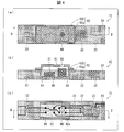
- (A) is a top view which shows schematic structure of the electronic device in Embodiment 1 of this invention, (b) is the sectional view on the AA line of (a).
- (A), (b), (c), (e), (f), and (g) are a plan view for explaining an example of a method for manufacturing the electronic device, and a cross-sectional view taken along the line BB in the plan view; ) Is a side cross-sectional view illustrating an example of the method for manufacturing the electronic device.
- (A) is a top view which shows the schematic structure of the electronic device in Embodiment 2 of this invention, (b) is CC sectional view taken on the line of (a).
- FIG. 2E is a cross-sectional view taken along line EE in the drawing
- FIG. 3E is a bottom view for explaining an example of a method for manufacturing the electronic device, and a cross-sectional view taken along line EE of the bottom view.
- FIG. 2E is side cross-sectional view taken along line EE in the drawing
- FIG. 3E is a bottom view for explaining an example of a method for manufacturing the electronic device, and a cross-sectional view taken along line EE of the bottom view.
- It is side surface sectional drawing which shows schematic structure of an electronic apparatus provided with the conventional electromagnetic shield.
- an electronic device in which a high-frequency functional component such as an amplifier, a phase shifter, or an attenuator is covered with a thin film conductive layer and is electromagnetically shielded will be described as an example of the electronic device of the present invention.
- the electromagnetic shield means that an electromagnetic wave such as a microwave band or a millimeter wave band emitted from a high-frequency radiation source is electromagnetically shielded, and the electromagnetic shield refers to an electromagnetic wave electromagnetically. It means a member to be shielded.
- an electronic device in which high-frequency functional parts such as an amplifier, a phase shifter, or an attenuator are electromagnetically shielded by a thin film conductive layer will be described as an example of the electronic device.
- the present invention can be applied to an electronic device in which various types of electronic components such as a microphone and various sensors such as a temperature and humidity sensor, an optical element, and a power supply IC are electromagnetically shielded, and a manufacturing method thereof.
- the electromagnetic shielding member may be a metal case instead of the thin film conductive layer.
- a part of the electromagnetic shielding member may be optionally opened, for example, an opening may be provided.
- FIG. 1A is a plan view showing a schematic configuration of an electronic apparatus 1A according to the first embodiment.
- FIG. 1B is a cross-sectional view taken along line AA in the plan view shown in FIG.
- the electronic device 1A of the present embodiment is a high-frequency functional component 21 (first electronic component) that is electromagnetically shielded by a conductive member 10 serving as an electromagnetic shield. And an electronic component 22 (second electronic component) not covered with the conductive member 10 and a resin molded body 23 formed so as to embed and fix the high-frequency functional component 21 and the electronic component 22. Yes.
- the conductive member 10 covers the high-frequency functional component 21 via the internal insulating layers 30 and 31 (insulating members), and the high-frequency functional component 21 and the electronic component 22 are formed on the surface of the resin molded body 23.
- the circuit 24 is electrically connected.
- the wiring circuit 24 and the electronic component 22 in a region not covered with the conductive member 10 on the resin molded body 23 are covered with an exposed insulating layer 32 formed on the resin molded body 23.
- the region where the exposed insulating layer 32 is formed may be set as appropriate, and the wiring circuit 24 and the electronic component 22 may not be all covered with the exposed insulating layer 32. .
- the conductive member 10 includes an embedded conductive layer 11 (first conductive member) embedded in the resin molded body 23 together with the high-frequency functional component 21, and an exposed conductive layer 12 (second conductive member) not embedded in the resin molded body 23. ) And a short-circuit conductive member 13 (third conductive member) that is embedded in the resin molded body 23 and electrically short-circuits the embedded conductive layer 11 and the exposed conductive layer 12 to each other.
- the embedded conductive layer 11 and the exposed conductive layer 12 are Ag thin films having a thickness of about 1 to 10 ⁇ m.
- the embedded conductive layer 11 and the exposed conductive layer 12 are only required to have conductivity, and can have a desired electromagnetic shielding characteristic by appropriately selecting a film thickness and a material.
- the exposed conductive layer 12 is preferably as thin as possible because the height of the portion protruding from the resin molded body 23 can be suppressed and the electronic device 1A can be thinned.
- the thickness of the buried conductive layer 11 and the exposed conductive layer 12 to 1 to 10 ⁇ m, it is possible to minimize the material used for forming these, compared to the case where a metal case or the like is used. Therefore, material costs can be reduced. Therefore, manufacturing cost can be reduced.
- the short-circuit conductive member 13 is a thin plate made of copper (Cu) or stainless steel having a thickness of 0.1 mm.
- the short-circuit conductive member 13 only needs to have conductivity, and the film thickness and material thereof are not particularly limited. However, the one having a certain thickness is deformed at the time of manufacturing described later (wrinkles). ) Is preferable because it can be suppressed.
- three short-circuit conductive members 13 are provided so as to surround the high-frequency functional component 21 when the surface of the resin molded body 23 is viewed in plan.
- the shape and the number of the short-circuit conductive members 13 are particularly limited as long as there is a gap capable of forming the wiring circuit 24 between the high-frequency functional component 21 and the electronic component 22 on the resin molded body 23. is not.
- the electromagnetic shielding characteristics of the conductive member 10 become better as the short-circuit conductive member 13 surrounds the high-frequency functional component 21 without a gap. This is because the area not covered by the conductive member 10 in the space around the high-frequency functional component 21 is reduced.
- the short-circuit conductive member 13 is not an essential component for the electronic apparatus 1A because it short-circuits the buried conductive layer 11 and the exposed conductive layer 12 to further improve the electromagnetic shielding characteristics of the conductive member 10.
- the high-frequency functional component 21 is an electronic component such as an amplifier, a phase shifter, or an attenuator, and two electronic devices 1A according to the present embodiment are provided.
- the number of high-frequency functional components 21 that are electromagnetically shielded by the conductive member 10 is not particularly limited.
- the high-frequency functional component 21 is provided with a connection electrode (not shown) on its surface, and a wiring circuit 24 is connected to the connection electrode.
- the high-frequency functional component 21 is embedded in the resin molded body 23 so that the connection electrode is on the same or substantially the same plane as the surface of the resin molded body 23.
- the present invention is not limited to this, and it is sufficient that at least a part of the high-frequency functional component 21 is embedded in the resin molding 23.
- the electronic component 22 is an electronic component such as a capacitor, resistor, or IC. In the electronic device 1A of the present embodiment, three electronic components 22 are provided. The number of electronic components 22 is not particularly limited.
- the electronic component 22 has a connection electrode (not shown) on its surface, and a wiring circuit 24 is connected to the connection electrode.
- the electronic component 22 is embedded in the resin molded body 23 such that the connection electrode is on the same or substantially the same plane as the surface of the resin molded body 23.
- the electronic component 22 is not limited to this, and at least a part of the electronic component 22 may be embedded in the resin molded body 23.
- the resin molded body 23 is a rectangular parallelepiped casing made of a resin such as polycarbonate (PC) or acrylonitrile butadiene styrene (ABS).
- the material of the resin molding 23 may be other types of resin.
- the shape of the resin molding 23 is not specifically limited.
- the internal insulating layers 30 and 31 are provided between the high-frequency functional component 21 and the conductive member 10 in a space formed by being surrounded by the conductive member 10, and the internal insulating layer 30 is embedded in the resin molded body 23.
- the internal insulating layer 31 is not embedded in the resin molded body 23.
- the internal insulating layer 30 is provided between the high-frequency functional component 21 and the embedded conductive layer 11, and is embedded in the resin molding 23 together with the high-frequency functional component 21 and the embedded conductive layer 11.
- the internal insulating layer 30 is an epoxy resin having a thickness of about 5 to 10 ⁇ m.
- the inner insulating layer 30 only needs to have insulating properties, and the film thickness and material can be appropriately selected.
- the inner insulating layer 30 may be made of glass or ceramics.
- the surface of the internal insulating layer 30 is flush with the surface of the resin molded body 23, and the wiring circuit 24 is formed on this surface. Yes.
- the inner insulating layer 30 is made of an insulating resin from the viewpoint of being required to have a certain degree of strength and flatness and suppressing the manufacturing cost.
- the other internal insulating layer 31 is provided between the high-frequency functional component 21 and the exposed conductive layer 12 and is not embedded in the resin molded body 23.
- the internal insulating layer 31 is an epoxy resin having a thickness of about 5 to 10 ⁇ m.
- the internal insulating layer 31 only needs to have insulating properties, and the film thickness and material can be selected as appropriate.
- the internal insulating layer 31 may be made of glass or ceramics, but is preferably made of an insulating resin.
- the wiring circuit 24 is electrically connected to the high-frequency functional component 21 and the electronic component 22 on the surface of the internal insulating layer 30 and the surface of the resin molding 23, and is electrically connected to the outside of the electronic device 1A. It is the conductive circuit formed in this.
- the high-frequency functional component 21 and the electronic component 22 are both such that the connection electrodes are on the same or substantially the same plane as the surfaces of the internal insulating layer 30 and the resin molded body 23. It is embedded in the resin molded body 23. Therefore, the wiring circuit 24 can be formed by spraying silver (Ag) ink using an ink jet printer, and the wiring circuit 24 can be easily formed.
- the wiring circuit 24 may be made of a material other than Ag, or may be formed by other methods, and the thickness of the wiring is not particularly limited.
- connection electrode of the high-frequency functional component 21 or the electronic component 22 and the plane formed by the surfaces of the inner insulating layer 30 and the resin molded body 23 is an inkjet.
- the wiring circuit 24 can be formed by printing by an apparatus such as a printer and is small enough (flat).
- the wiring circuit 24 is formed so as not to contact the short-circuit conductive member 13. Further, the wiring circuit 24 and the exposed conductive layer 12 are insulated by the internal insulating layer 31.
- the exposed insulating layer 32 is an epoxy resin having a thickness of about 5 to 10 ⁇ m formed so as to cover the electronic component 22 and the wiring circuit 24, and has a role as a protective film (resist) for protecting them.
- the exposed insulating layer 32 only needs to have insulating properties, and the film thickness and material can be appropriately selected.
- FIG. 2 are diagrams for explaining an example of a method for manufacturing the electronic device 1A of the present embodiment, and are plan views of the electronic device 1A, respectively. And a cross-sectional view taken along line BB in the plan view.
- FIG. 2D is a side cross-sectional view for explaining an example of the manufacturing method of the electronic device 1A of the present embodiment.
- the material of the temporary fixing film 40 for example, polyethylene terephthalate (PET), polyethylene naphthalate (PEN), polyphenylene sulfide (PPS) or the like can be used.
- PET polyethylene terephthalate
- PEN polyethylene naphthalate
- PPS polyphenylene sulfide
- the temporary fixing film 40 is preferably made of a material that transmits ultraviolet rays and has flexibility for reasons described later.
- the temporary fixing film 40 may be a carrier tape, a glass epoxy substrate, or the like.
- the material of the temporary fixing film 40 is not particularly limited as long as various electronic components can be temporarily fixed and can be peeled off after the electronic device 1A is manufactured.
- the temporary fixing can be performed using, for example, an ultraviolet curable adhesive (not shown) applied to one surface of the temporary fixing film 40, for example.
- an ultraviolet curable adhesive (not shown) applied to one surface of the temporary fixing film 40, for example.
- GL-3005H manufactured by Glue Lab as an adhesive is applied to a 50 ⁇ m PET temporary fixing film 40 in a thickness of 2 to 3 ⁇ m.
- This application may be performed using an ink jet printing method.
- the high-frequency functional component 21, the electronic component 22, and the short-circuit conductive member 13 are determined and installed.
- the adhesive is cured by irradiating ultraviolet rays having an intensity of 3000 mJ / cm 2 , and the high-frequency functional component 21, the electronic component 22, and the short-circuit conductive member 13 are temporarily fixed to the temporary fixing film 40.
- the short-circuit conductive member 13 is preferably a metal material having a thickness of 0.1 mm or more.
- the short-circuit conductive member 13 may be wrinkled when the short-circuit conductive member 13 is industrially transported and attached to the temporarily fixing film 40.
- the electronic device 1A Problems occur as products. Therefore, when the short-circuit conductive member 13 is a metal material having a thickness of 0.1 mm or more, the short-circuit conductive member 13 can have a certain degree of rigidity, and the above-described problem can hardly occur.
- First electromagnetic shielding step As shown in FIGS. 2 (b) and 2 (c), internal insulation having a thickness of about 5 to 10 ⁇ m is formed on the surface of the high-frequency functional component 21 temporarily fixed on the temporary fixing film 40 after the pasting and temporary fixing step.
- a layer 30 (first insulating member) is formed, and the embedded conductive layer 11 (first conductive member) made of Ag having a thickness of about 1 to 10 ⁇ m is formed on the high-frequency functional component 21 via the internal insulating layer 30.
- embers are laminated (first electromagnetic shielding step).
- the region where the internal insulating layer 30 is formed is a region surrounded by the short-circuit conductive member 13 on the temporary fixing film 40 and a region not including the short-circuit conductive member 13.
- the internal insulating layer 30 may be formed so as to partially cover the surface of the short-circuit conductive member 13, but is formed so that the embedded conductive layer 11 and the surface of the short-circuit conductive member 13 are in contact with each other.
- the method for forming the inner insulating layer 30 and the buried conductive layer 11 is, for example, an ink jet printing method, but is not particularly limited.
- the ink jet printing method is used, the internal insulating layer 30 and the embedded conductive layer 11 can be easily selectively laminated in a desired region including on the surface of the high-frequency functional component 21, so that the material cost and manufacturing Cost can be reduced.
- the screen printing method or the like may be inappropriate because there is a step in the high-frequency functional component 21.
- the high-frequency functional component 21 is partially surrounded by the buried conductive layer 11 and the short-circuit conductive member 13 and partially electromagnetically shielded.
- the conditions for performing the injection molding may be appropriately selected according to the resin constituting the resin molded body 23.
- the injection molding is performed at an injection resin temperature of 270 ° C. and an injection pressure of 100 MPa.
- injection molding is performed at an injection resin temperature of 180 ° C. and an injection pressure of 20 kgf / cm 2 .
- a variety of resin materials can be adopted as the resin constituting the resin molded body 23. Moreover, the conditions for performing injection molding are not particularly limited.
- the resin molded body 23 in which the high-frequency functional component 21, the electronic component 22, and the short-circuit conductive member 13 are embedded is taken out from the mold cavity 43 and temporarily fixed.
- the film 40 is separated (removal step).
- the internal insulating layer 30 and the embedded conductive layer 11 are embedded in the resin molded body 23 together with the high-frequency functional component 21.
- the temporarily fixed film 40 is a PET film
- the temporarily fixed film 40 is greatly deformed and peeled off from the resin molded body 23 due to the heat change during the resin molding step. 23 can be easily separated.
- circuit formation process As shown in FIG. 2 (e), after the taking-out step, on the surface formed by the resin molded body 23 and the internal insulating layer 30, the connection between the high-frequency functional component 21 and the electronic component 22 exposed on the surface is performed.
- the electrodes are connected by the wiring circuit 24 (circuit formation process).
- the wiring circuit 24 can be formed by a method of spraying a conductive material (for example, silver ink or the like) by an inkjet printing method or the like, a method using an aerosol, a method using a dispenser, or the like.
- the wiring circuit 24 can be formed easily and with a high degree of freedom in circuit design using a method selected as appropriate, and each electronic component can be easily electrically connected without soldering or the like. Furthermore, industrially, since each electronic component can be connected after the position of each electronic component is determined, for example, each electronic component can be connected more accurately and easily than when the electronic component is aligned with a printed circuit board. Electronic components can be electrically connected.
- the wiring circuit 24 is formed on the surface formed by the resin molded body 23 and the internal insulating layer 30 so as not to come into contact with the short-circuit conductive member 13, that is, escape from the short-circuit conductive member 13. This is because the short-circuit conductive member 13 is also exposed on the surface formed by the resin molded body 23 and the internal insulating layer 30, but a problem occurs when the wiring circuit 24 touches the short-circuit conductive member 13.
- an exposed conductive layer 12 (second conductive member) made of Ag having a thickness of about 1 to 10 ⁇ m is laminated so as to cover the high-frequency functional component 21 via the internal insulating layer 31 (second insulating member) ( Second electromagnetic shielding step).
- Second electromagnetic shielding step Second electromagnetic shielding step
- the above-mentioned insulating protective film is industrially formed integrally by an ink jet printing method or the like, but can be divided into an internal insulating layer 31 and an exposed insulating layer 32.
- the region where the internal insulating layer 31 is formed is a region surrounded by the short-circuit conductive member 13 when the surface of the resin molded body 23 is viewed in plan and does not include the top of the short-circuit conductive member 13.
- the inner insulating layer 31 may be formed so as to partially cover the surface of the short-circuit conductive member 13, but the exposed conductive layer 12 and the surface of the short-circuit conductive member 13 are in contact with each other.
- the exposed insulating layer 32 is formed in a region not surrounded by the short-circuit conductive member 13 so as to protect the electronic component 22 and the wiring circuit 24.
- the method for forming the inner insulating layer 31 and the exposed insulating layer 32 is, for example, an inkjet printing method, but is not particularly limited. When the ink jet printing method is used, the internal insulating layer 31 and the exposed insulating layer 32 can be easily selectively formed avoiding the short-circuit conductive member 13.
- the method for forming the exposed conductive layer 12 is, for example, an inkjet printing method, but is not particularly limited.
- At least one high-frequency functional component 21 and conductive member 10 that electromagnetically shields high-frequency functional component 21 are provided, and at least one of high-frequency functional component 21 is included.
- the part and at least a part of the conductive member 10 are embedded and fixed in the resin molded body 23.
- an electronic component is mounted on a printed circuit board, and the electronic component is covered with a metal case or the like, and the electronic component and the metal case protrude from the printed circuit board. Furthermore, parts such as metal cases are required to have a certain size for industrial transport and alignment, and there is a limit to downsizing and thinning the electronic device.
- the electronic apparatus 1A of the present embodiment it is not necessary to use a metal case or the like, and at least a part of the high-frequency functional component 21 is embedded in the resin molded body 23. Therefore, the part which protrudes from the resin molding 23 can be made low, and 1 A of electronic devices can reduce the dimension of a height direction, and can be reduced in size and thickness.
- the electronic device 1A can be manufactured by the manufacturing process as described above, and the manufacturing process does not include industrially complicated processes. Therefore, manufacturing cost can be suppressed.
- the wiring circuit 24 can be designed freely with few restrictions except that the wiring circuit 24 is not in contact with the short-circuit conductive member 13 as in the circuit forming step. . Therefore, the degree of freedom in wiring circuit design can be increased.
- the electronic apparatus 1A in the present embodiment at least a part of the electronic component 22 that is not electromagnetically shielded is embedded in the resin molded body 23. Therefore, even if various types of electronic components 22 are provided, the electronic device 1A can be reduced in thickness by reducing the dimension in the height direction.
- conductive member 10 includes embedded conductive layer 11, exposed conductive layer 12, and short-circuit conductive member 13, and embedded conductive layer 11 and exposed conductive layer 12 are included. Are electrically connected to each other through the short-circuit conductive member 13.
- the high-frequency functional component 21 is surrounded by the conductive member 10 with almost no gap, and is highly electromagnetically shielded.
- the method for manufacturing electronic device 1A in the present embodiment as described above, positioning is performed on temporary fixing film 40, high-frequency functional component 21 and electronic component 22 are affixed, and internal structure is formed on high-frequency functional component 21.
- the insulating layer 30 and the buried conductive layer 11 are stacked. Thereafter, the high-frequency functional component 21 and the electronic component 22 are embedded in the resin molded body 23 to form a wiring circuit 24, and the internal insulating layer 31, the exposed insulating layer 32, and the exposed conductive layer 12 are laminated.
- the electronic device 1A can be manufactured through such a stacking-type continuous process.
- the electronic device 1A of the present embodiment can be manufactured while suppressing the manufacturing cost.
- the electronic device 1A according to the present embodiment does not require a space necessary for processing such as soldering, installation of a conductive case, or bending of a printed circuit board, and can improve the degree of freedom in circuit design. .
- a high-frequency functional component 21 such as an amplifier, a phase shifter, or an attenuator is covered with an exposed conductive layer 12 having a thickness of about 1 to 10 ⁇ m and electromagnetically shielded. 1A
- a metal case is provided with a space inside a high frequency functional component 51 such as various sensors such as a microphone and a temperature / humidity sensor or an optical element.
- the electronic apparatus 1B covered with 52 and electromagnetically shielded will be described.
- the high-frequency functional component to be electromagnetically shielded includes various sensors such as a microphone and a temperature / humidity sensor, or the high-frequency functional component 51 such as an optical element, the high-frequency functional component 51 and the electromagnetic shield that covers the high-frequency functional component 51 In such a case, the electronic device 1B of the present embodiment can be obtained.
- FIG. 3A is a plan view showing a schematic configuration of the electronic apparatus 1B according to the second embodiment.
- FIG. 3B is a cross-sectional view taken along the line CC of the plan view shown in FIG.
- the high frequency functional component 21 and the high frequency functional component 51 are formed on the resin molded body 23 together with the embedded conductive layer 11 and the internal insulating layer 30. It is embedded and fixed, provided with a space inside and covered with a metal case 52.
- the embedded conductive layer 11 and the metal case 52 are electrically short-circuited to each other by the short-circuit conductive member 13 provided therebetween.
- the high-frequency functional component 51 is electromagnetically shielded by the buried conductive layer 11, the metal case 52, and the short-circuit conductive member 13.
- the high frequency functional component 21, the high frequency functional component 51, and the electronic component 22 are electrically connected by a wiring circuit 24.
- the high frequency functional component 51 is an electronic component such as a microphone, various sensors such as a temperature / humidity sensor, or an optical element, and one electronic device 1B of the present embodiment is provided.
- the number of high frequency functional components 51 is not particularly limited.
- the metal case 52 is obtained by processing metal into a case shape so as to form a space on the high-frequency functional component 51.
- the metal case 52 and the short-circuit conductive member 13 embedded in the resin molded body 23 are fixed by a conductive adhesive (not shown) or by welding or the like.
- the fixed metal case 52 is electrically short-circuited with the embedded conductive layer 11 embedded in the resin molded body 23 to constitute an electromagnetic shield that covers the high-frequency functional component 51.
- the metal case 52 may have a conductive layer formed on the surface of a resin case by metal coating or the like.
- the metal case 52 may be provided only on the high-frequency functional component 51, and the other part (the high-frequency functional component 21) may be covered with the exposed conductive layer 12.
- the metal case 52 and the exposed conductive layer 12 may be connected and fixed so as to be electrically short-circuited with each other.
- the metal case 52 is provided with an opening 53 above the high-frequency functional component 51.
- the internal insulating layer 31 is not formed on the high frequency functional component 51. This is because the high-frequency functional component 51 such as a microphone or a sensor needs to be in contact with outside air.
- the inner insulating layer 31 is formed except on the high-frequency functional component 51, and the metal case 52 is covered so as to be in contact with the surface of the short-circuit conductive member 13. Can be fixed and manufactured so as to be connected.
- the high frequency functional component 51 is electromagnetically shielded by covering the metal case 52 provided with the opening 53.
- the exposed conductive layer 12 instead of the metal case 52 may be formed except on the high-frequency functional component 51. Thereby, an opening can be formed on the high-frequency functional component 51 to perform electromagnetic shielding.
- the high-frequency functional component 51 that requires at least one of a space or an opening in the upper portion can be electromagnetically shielded.
- the electronic device 1B in which the high frequency functional component 51 embedded in the resin molding 23 is provided with a space and covered with the metal case 52 and electromagnetically shielded is described.
- a metal metal casing 62 is provided as a conductive member that accommodates the high frequency functional component 51 therein, and the high frequency functional component is provided.
- An electronic device 1 ⁇ / b> C having a configuration in which at least a part of 51 and the metal casing 62 are embedded in the resin molded body 23 will be described.
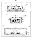
- FIG. 4A is a plan view showing a schematic configuration of the electronic apparatus 1C according to the third embodiment.
- FIG. 4B is a cross-sectional view taken along line DD of the plan view shown in FIG.
- FIG. 4C is a bottom view of the electronic apparatus 1C.
- the high-frequency functional component to be electromagnetically shielded includes various sensors such as a microphone and a temperature / humidity sensor, or the high-frequency functional component 51 such as an optical element, a metal casing made of a metal material.
- the body 62 may be configured to be electromagnetically shielded by accommodating the high-frequency functional component 51 with a space provided on the high-frequency functional component 51.
- the description of Patent Document 2 can be referred to as appropriate for the configuration of the electronic module in which the electronic component is housed in the metal casing 62 and the manufacturing method thereof.
- the high-frequency functional component 21 and the high-frequency functional component 51 include a first box 62a and a second box.
- the first box body 62a is embedded in the resin molded body 23 together with the high-frequency functional component 21 and the high-frequency functional component 51 housed therein.
- An electronic component 22 is also embedded in the resin molded body 23.
- the first box body 62a and the second box body 62b are both obtained by sheet metal working, and are both box-shaped members having openings.
- the metal casing 62 is configured by fixing the first box body 62a and the second box body 62b so that their openings face each other. The fixing is performed by a conductive adhesive (not shown) or by welding. As a result, the first box body 62a and the second box body 62b are electrically short-circuited with each other, and the metal casing 62 serves as an electromagnetic shield that covers the high-frequency functional component 21 and the high-frequency functional component 51.
- An example of a material (metal plate) used for the first box 62a is a nickel-iron alloy (42 alloy) plate having a thickness of 0.15 mm.
- An example of the material (metal plate) used for the second box 62b is a nickel-iron alloy (42 alloy) plate having a thickness of 0.12 mm.
- the first box 62a and the second box 62b may be formed by forming a conductive layer on the surface of a resin box by metal coating or the like. Further, the second box 62b may be provided only on the high-frequency functional component 51, and the other part (the high-frequency functional component 21) may be covered with the exposed conductive layer 12. In this case, the second box 62b and the exposed conductive layer 12 may be connected and fixed so as to be electrically short-circuited with each other.
- An insulating layer 63 is provided outside the first box 62a (here, the outside on the bottom side).
- An example of the insulating layer 63 is a layer made of an epoxy adhesive.
- the high-frequency functional component 21 and the high-frequency functional component 51 are fixed by an insulating potting portion 64 (insulating member) filled and cured in the first box 62a.
- An example of a potting agent that forms the potting portion 64 is an epoxy sealant.
- the high-frequency functional component (tall component) 51 has a height higher than the depth of the first box 62 a, and the upper portion of the high-frequency functional component 51 is exposed from the potting portion 64. .
- the through-hole 65 is provided in the bottom plate of the 1st box 62a.
- the through-hole 65 is provided for drawing out a lead wire (not shown) such as a gold wire connected to the high-frequency functional component 21 and the high-frequency functional component 51 to the surface of the insulating layer 63. That is, the conducting wire is inserted into the through-hole 65, one end side of the conducting wire is electrically connected to the high frequency functional component 21 or the high frequency functional component 51, and the other end side is drawn to the surface of the insulating layer 63. Thus, the wiring circuit 24 is electrically connected. Thereby, the high frequency functional component 21 and the high frequency functional component 51 are electrically connected to the electronic component 22.
- the through holes 65 are provided at eight locations, but it goes without saying that the number of the through holes 65 is appropriately set depending on the type and number of electronic components to be mounted.
- the second box 62b is not embedded in the resin molded body 23, and an opening 66 is provided above the high-frequency functional component 51. And the upper part of the high frequency functional component 51 is exposed from the potting part 64.
- the electronic device 1 ⁇ / b> C has a space above the high frequency functional component 51, and the high frequency functional component 51 comes into contact with the outside air.
- FIGS. 5A, 5B, and 5D are side cross-sectional views for explaining an example of a method for manufacturing the electronic device 1C according to the present embodiment.
- FIGS. 5C and 5F are diagrams for explaining an example of the manufacturing method of the electronic device 1C of the present embodiment. Each of the plan view of the electronic device 1C and the view along the line EE in the plan view are shown. It consists of a sectional view.
- FIG. 5E is a diagram for explaining an example of the manufacturing method of the electronic device 1C according to the present embodiment. From the bottom view of the electronic device 1C and the sectional view taken along the line EE of the bottom view, FIG. It has become.
- a first box 62a having an insulating layer 63 and a through hole 65 is prepared.
- the high-frequency functional component 21 and the high-frequency functional component 51 are arranged inside the first box 62a (component housing step), and the lead wires (Fig. After pulling out (not shown) from the through-hole 65 (lead wire drawing step), a liquid potting agent (epoxy sealant) is filled (component fixing step). As the liquid potting agent is cured, the above-described potting portion 64 is formed. Thereby, the high frequency functional component 21 and the high frequency functional component 51 are fixed in the first box body 62a (first electromagnetic shielding step).
- a liquid potting agent epoxy sealant
- the potting unit 64 does not cover the portion where the first box 62a is connected and fixed later to the second box 62b. Moreover, since the high frequency functional component 51 has a height higher than the depth of the concave portion of the first box 62 a, the upper portion of the high frequency functional component 51 protrudes from the potting portion 64.
- the first box body 62 a is temporarily fixed so that the surface on which the insulating layer 63 and the through hole 65 are formed is in contact with the temporary fixing film 40.
- the electronic component 22 is fixed such that each connection electrode (not shown) is in contact with the temporary fixing film 40.
- the temporarily fixing film 40 is placed on the lower mold 72. Then, a resin molding process is performed between the upper mold 71 and the lower mold 72 as in the first embodiment, and a take-out process is performed. At this time, the upper mold 71 is provided with a recess 71 a at a position corresponding to the upper portion of the high-frequency functional component 51 protruding from the potting portion 64.
- connection electrode of the electronic component 22 exposed on the surface of the resin molded body 23 is connected by the wiring circuit 24 (circuit formation step).
- the second box 62 b is electrically connected and fixed to the first box 62 a by a conductive adhesive or welding to form a metal casing 62.
- the metal casing 62 covers the high-frequency functional component 21 and the high-frequency functional component 51, completes the electromagnetic shield structure, and the electronic device 1C in the present embodiment can be obtained.
- the metal casing 62 is deformed at the time of resin injection molding. Further, it is possible to prevent the occurrence of quality problems such as disconnection of the electrical connection of the wiring.
- an electronic device includes at least one electronic component, at least one conductive member that electromagnetically shields the electronic component, at least a part of the at least one electronic component, and the electronic device. And a resin molded body that embeds and fixes at least part of a conductive member that electromagnetically shields the electronic component.
- At least one electronic component is electromagnetically shielded by the conductive member, and at least a part of the electronic component and at least a part of the conductive member are embedded and fixed in the resin molded body. . That is, the height of the portion protruding on the resin molded body can be suppressed. Therefore, it is possible to reduce the size of the electronic device in the height direction and reduce the thickness.
- such a structure can be produced, for example, by providing a conductive member on one side of the electronic component and electromagnetically shielding it, then performing resin injection molding, and further providing a conductive member on the other side of the electronic component. it can.
- a wiring circuit can be formed after the injection molding of the resin and before the conductive member is further provided on the other side of the electronic component. Therefore, the manufacturing process can be simplified, and the degree of freedom in wiring circuit design can be increased.
- an electronic device provided with an electromagnetic shield, it is possible to provide an electronic device that can be manufactured at a reduced thickness, can be thinned, and has a high degree of freedom in wiring circuit design, and a method for manufacturing the electronic device.
- the electronic device further includes a first electronic component that is the electromagnetically shielded electronic component, and a second electronic component that is not electromagnetically shielded, and the second electronic component is It is preferable that at least a part of the resin molding is embedded.
- the second electronic component that is not electromagnetically shielded is provided, and at least a part of the second electronic component is embedded in the resin molded body. Therefore, even in an electronic device including the second electronic component, the height dimension can be reduced and the electronic device can be thinned.
- first electronic component and the second electronic component can be electrically connected by a wiring circuit, and an electronic device having various types and numbers of electronic components can be provided.
- the first electronic component is further fixed by an insulating member provided in a space formed by being surrounded by the conductive member, and at least the insulating member It is preferable that a part is embedded in the resin molded body together with at least a part of the first electronic component and at least a part of the conductive member.
- the first electronic component and the conductive member are insulated by the insulating member, and at least a part of the insulating member is embedded in the resin molded body. Therefore, even if the insulating member is provided, the height of the electronic device can be reduced and the electronic device can be thinned.
- the conductive member further includes a first conductive member embedded in the resin molded body, a second conductive member not embedded in the resin molded body, and the first At least one third conductive member provided between the first conductive member and the second conductive member, and the first conductive member and the second conductive member are the third conductive member. It is preferable that they are electrically connected to each other through the members.
- the first electronic component is surrounded by the first conductive member, the second conductive member, and the third conductive member. For this reason, the first electronic component can be electromagnetically shielded to a higher degree than when the third conductive member is not provided.
- the first conductive member and the second conductive member are thin films having a thickness of 1 ⁇ m to 10 ⁇ m.
- the first conductive member and the second conductive member can be formed by a method of forming a thin film such as an inkjet printing method. Moreover, the material to be used can be made the minimum necessary, and the member cost can be reduced as compared with the case of using a metal case or the like. Therefore, manufacturing cost can be reduced.
- the third conductive member is a metal material having a thickness of 0.1 mm or more.
- the third conductive member can have a certain degree of rigidity. For this reason, it is possible to prevent the third conductive member from being deformed, for example, wrinkled during industrial conveyance, and causing a problem as a product.
- the electrode of the first electronic component and the electrode of the second electronic component may further include a surface of the resin molded body and a surface of an insulating member embedded in the resin molded body.
- the wiring is connected so as not to contact the third conductive member, and the insulation between the wiring connected and the second conductive member is not embedded in the resin molding It is preferably insulated by a member or air.
- an electronic device in which the electrode of the first electronic component and the electrode of the second electronic component are connected by wiring can be provided.
- the electrode of the first electronic component and the electrode of the second electronic component are located on the same or substantially the same plane as the surface of the resin molded body. Is preferred.
- the wiring connection between the electrode of the first electronic component and the electrode of the second electronic component can be easily performed using an apparatus such as an ink jet printer.
- the second conductive member may further include an opening formed immediately above at least one of the first electronic components.
- the conductive member is a housing made of a metal material, and the housing is fixed to the resin molded body, which is fixed so that the openings of each other face each other.
- the first box body is embedded and the second box body protrudes from the surface of the resin molded body, and an insulating layer is provided outside the first box body.
- the box of 1 is provided with a through hole for drawing out the conductive wire connected to the first electronic component to the surface of the insulating layer, and the surface of the insulating layer and the outlet of the through hole are It can be assumed that it is located on the same surface as the back surface of the resin molded body.
- the first box housing the first electronic component is embedded in the resin molded body, and the second box projects from the surface of the resin molded body. Therefore, even in a configuration using such a housing, the height dimension of the electronic device can be reduced and the electronic device can be thinned.
- the second electronic component is further embedded with an electrode exposed on the back surface of the resin molded body, and a conductive wire connected to the first electronic component; It can be assumed that the electrode of the second electronic component is wire-connected on the back surface of the resin molded body.
- the electronic device in which the casing made of a metal material is a conductive member the electronic device in which the electrode of the first electronic component and the electrode of the second electronic component are connected by wiring can do.
- the wiring connection is printed with a conductive material.
- wiring can be easily performed with the minimum necessary material. Moreover, when forming the protective film which covers wiring, the thickness of the protective film can be made thin. Therefore, it is possible to reduce the manufacturing cost by suppressing the member cost.
- An electronic device manufacturing method includes a temporary fixing step of temporarily fixing at least one electronic component to a temporary fixing member, a first insulating member with respect to at least one of the electronic components, and A first electromagnetic shielding step of covering and electromagnetically shielding with a first conductive member; and a temporary fixing member after the first electromagnetic shielding step, the electronic component, the first insulating member, and the first Resin that is placed in a mold with the conductive member temporarily fixed, and resin-molded so that at least a part of each of the electronic component, the first insulating member, and the first conductive member is embedded.
- the by which side is characterized by including a second electromagnetic shielding step of electromagnetically shielding coated by the second conductive member on the opposite side.
- the electronic component positioning is performed on the temporary fixing member, the electronic component is attached, and one side of the electronic component is covered with the first insulating member and the first conductive member to be electromagnetically shielded, and then resin-molded.
- an electronic component, a first insulating member, and a first conductive member can be obtained embedded in the resin molded body.
- the electronic component can be electromagnetically shielded by covering the electronic component with a second conductive member.
- the electronic component, the first insulating member, and the first conductive member are embedded in the resin molded body, and the second conductive member can be projected on the resin molded body. Further, the wiring circuit can be formed after the take-out process and before the second electromagnetic shielding process.
- a conductive thin plate having conductivity is attached to the temporary fixing member in the temporary attachment step, and the second electromagnetic wave is provided after the removal step.
- a wiring circuit connected to the electrode of the electronic component is formed on the surface formed by the resin molded body and the first insulating member so that the wiring does not contact the conductive thin plate.
- the second electromagnetic shielding step includes laminating a second insulating member on the wiring circuit and the electronic component except for the conductive thin plate portion, and subsequently the electronic component. It is preferable that the second conductive member is laminated on the conductive thin plate including the conductive thin plate.
- the wiring circuit can be appropriately formed in the configuration in which the conductive thin plate is embedded in the resin molded body. Also, the second insulating member and the second conductive member are stacked on the electronic component, and the electronic component is surrounded by the first conductive member, the second conductive member, and the conductive thin plate to be highly electromagnetically shielded. Can be.
- a method for manufacturing an electronic device in which the first insulating member, the first conductive member, the second insulating member, the second conductive member, and the wiring circuit are respectively printed by an inkjet method. It is preferable to form using.
- Each circuit can be formed, and the manufacturing cost can be reduced.
- the first electromagnetic shielding step further includes a first as the first conductive member, wherein the first electromagnetic shielding step has conductivity and an insulating layer is formed outside.
- a component housing step for housing at least one of the electronic components in the box, and a lead wire connected to the electronic component is drawn through the through hole provided in the first box to the surface of the insulating layer.
- an electronic device can be manufactured using an electronic component accommodated in the first box.
- Such an electronic component housed in the first box may be manufactured for another purpose, so that the degree of freedom of the manufacturing process is improved and the manufacturing cost is reduced. Can do.
- the second electromagnetic shielding step further includes a second box body having conductivity and having an opening formed in a part thereof. It can be assumed that a housing that includes the electronic component is formed by being fixed so that the first box is positioned directly above the electronic component and the openings of the first box face each other. .
- the component housing step further includes a height as the electronic component that is taller than a depth of the first box in the first box. At least one part is accommodated, and the resin molding step includes the tall part between an upper mold in which a depression is provided in a portion where the tall part abuts, and a lower mold,
- the first insulating member and the first conductive member may be resin-molded so as to be embedded at least in part.
- the electronic device can be manufactured using the tall parts accommodated in the first box.
- the method for manufacturing an electronic device further includes: the electronic device on the surface formed by the resin molded body and the insulating layer after the take-out step and before the second electromagnetic shielding step. It may further include a circuit forming step of forming a wiring circuit connected to the conductive wire connected to the component.
- the circuit forming step is further performed by spraying conductive ink to print a wiring to form a wiring circuit.
- wiring connection can be easily performed using an apparatus such as an ink jet printer.
Landscapes
- Engineering & Computer Science (AREA)
- Microelectronics & Electronic Packaging (AREA)
- Manufacturing & Machinery (AREA)
- Physics & Mathematics (AREA)
- Electromagnetism (AREA)
- Shielding Devices Or Components To Electric Or Magnetic Fields (AREA)
- Health & Medical Sciences (AREA)
- Toxicology (AREA)
- Manufacturing Of Printed Wiring (AREA)
- Condensed Matter Physics & Semiconductors (AREA)
- General Physics & Mathematics (AREA)
Abstract
La présente invention concerne : un dispositif électronique comprenant un blindage électromagnétique, le coût de production étant réduit, l'épaisseur pouvant être diminuée, et le degré de liberté de la conception du circuit de câblage étant élevé ; et un procédé de production du dispositif électronique. Un dispositif électronique (1A) est pourvu des éléments suivants : au moins une partie fonctionnelle à haute fréquence (21) ; un élément conducteur (10) pour protéger de façon électromagnétique l'au moins une partie fonctionnelle à haute fréquence (21) ; et un corps moulé en résine (23) pour incorporer et fixer au moins une partie de la partie fonctionnelle à haute fréquence (21) et au moins une partie de l'élément conducteur (10).
Priority Applications (5)
| Application Number | Priority Date | Filing Date | Title |
|---|---|---|---|
| US15/756,114 US10375867B2 (en) | 2016-04-27 | 2017-03-27 | Electronic device and method for producing same |
| CN201780002915.8A CN108029229B (zh) | 2016-04-27 | 2017-03-27 | 电子装置及其制造方法 |
| EP17789154.6A EP3451810B1 (fr) | 2016-04-27 | 2017-03-27 | Dispositif électronique et son procédé de fabrication |
| EP19210685.4A EP3672378B1 (fr) | 2016-04-27 | 2017-03-27 | Dispositif électronique et son procédé de fabrication |
| KR1020187005604A KR101991644B1 (ko) | 2016-04-27 | 2017-03-27 | 전자 장치 및 그 제조 방법 |
Applications Claiming Priority (2)
| Application Number | Priority Date | Filing Date | Title |
|---|---|---|---|
| JP2016089369A JP6648626B2 (ja) | 2016-04-27 | 2016-04-27 | 電子装置およびその製造方法 |
| JP2016-089369 | 2016-04-27 |
Publications (1)
| Publication Number | Publication Date |
|---|---|
| WO2017187865A1 true WO2017187865A1 (fr) | 2017-11-02 |
Family
ID=60160397
Family Applications (1)
| Application Number | Title | Priority Date | Filing Date |
|---|---|---|---|
| PCT/JP2017/012469 Ceased WO2017187865A1 (fr) | 2016-04-27 | 2017-03-27 | Dispositif électronique et son procédé de fabrication |
Country Status (7)
| Country | Link |
|---|---|
| US (1) | US10375867B2 (fr) |
| EP (2) | EP3672378B1 (fr) |
| JP (1) | JP6648626B2 (fr) |
| KR (1) | KR101991644B1 (fr) |
| CN (3) | CN110996549A (fr) |
| TW (1) | TWI629929B (fr) |
| WO (1) | WO2017187865A1 (fr) |
Cited By (1)
| Publication number | Priority date | Publication date | Assignee | Title |
|---|---|---|---|---|
| WO2019098029A1 (fr) * | 2017-11-15 | 2019-05-23 | オムロン株式会社 | Dispositif électronique et son procédé de fabrication |
Families Citing this family (12)
| Publication number | Priority date | Publication date | Assignee | Title |
|---|---|---|---|---|
| JP6693441B2 (ja) * | 2017-02-27 | 2020-05-13 | オムロン株式会社 | 電子装置およびその製造方法 |
| US10804119B2 (en) * | 2017-03-15 | 2020-10-13 | STATS ChipPAC Pte. Ltd. | Method of forming SIP module over film layer |
| CN109712937B (zh) * | 2019-01-02 | 2020-12-18 | 北京振兴计量测试研究所 | 一种共晶载体及微波装置 |
| US12103167B2 (en) * | 2019-07-17 | 2024-10-01 | Abb Schweiz Ag | Robot arm link with embedded cables and robot |
| DE102019216720A1 (de) * | 2019-10-30 | 2021-05-06 | Robert Bosch Gmbh | Verfahren und Vorrichtung zum Erzeugen eines Elektronikmoduls |
| KR102276278B1 (ko) * | 2019-11-05 | 2021-07-12 | 주식회사 이큐셀 | 반도체 공정 진단을 위한 플라즈마 센서 장치 및 이의 제조 방법 |
| KR102246964B1 (ko) * | 2019-11-05 | 2021-04-30 | 주식회사 이큐셀 | 반도체 공정 진단을 위한 플라즈마 센서 장치 및 이의 제조 방법 |
| JP7417828B2 (ja) * | 2019-11-21 | 2024-01-19 | パナソニックIpマネジメント株式会社 | 電子機能用成形体及びその製造方法、並びに電子機能用成形体を用いた操作装置 |
| EP4017226B1 (fr) * | 2020-07-07 | 2025-04-16 | Shennan Circuits Co., Ltd. | Carte de circuit intégré et procédé de fabrication pour carte de circuit intégré |
| CN112103269B (zh) * | 2020-08-07 | 2022-09-20 | 珠海越亚半导体股份有限公司 | 一种具有屏蔽腔的嵌入式封装结构及其制造方法 |
| WO2022092386A1 (fr) * | 2020-10-30 | 2022-05-05 | 주식회사 이큐셀 | Dispositif capteur permettant de diagnostiquer un processus de semi-conducteur |
| CN114188312B (zh) * | 2022-02-17 | 2022-07-08 | 甬矽电子(宁波)股份有限公司 | 封装屏蔽结构和屏蔽结构制作方法 |
Citations (6)
| Publication number | Priority date | Publication date | Assignee | Title |
|---|---|---|---|---|
| JPS6155384U (fr) * | 1984-09-17 | 1986-04-14 | ||
| JPH0579995U (ja) * | 1992-04-03 | 1993-10-29 | 日本無線株式会社 | 高周波シールド構造を有する多層配線基板 |
| JPH06501137A (ja) * | 1991-06-14 | 1994-01-27 | テレフオンアクチーボラゲツト エル エム エリクソン | 横方向の導電パターンと遮へい区域とを有する回路板及びその回路板を製造する方法 |
| JP2001102789A (ja) * | 1999-09-30 | 2001-04-13 | Toshiba Corp | 高周波遮蔽回路構造 |
| JP2001274034A (ja) * | 2000-01-20 | 2001-10-05 | Shinko Electric Ind Co Ltd | 電子部品パッケージ |
| JP2004134669A (ja) * | 2002-10-11 | 2004-04-30 | Sony Corp | Icチップ内蔵多層基板及びその製造方法 |
Family Cites Families (25)
| Publication number | Priority date | Publication date | Assignee | Title |
|---|---|---|---|---|
| US6686649B1 (en) * | 2001-05-14 | 2004-02-03 | Amkor Technology, Inc. | Multi-chip semiconductor package with integral shield and antenna |
| WO2004093506A2 (fr) * | 2003-04-15 | 2004-10-28 | Wavezero, Inc. | Blindage antiparasite electromagnetique destine a une plaque de circuit imprime |
| JP2005207703A (ja) * | 2004-01-26 | 2005-08-04 | Sekisui House Ltd | 免震建物におけるエアコン室外機の取付構造 |
| JP2006100302A (ja) | 2004-09-28 | 2006-04-13 | Sharp Corp | 高周波モジュールおよびその製造方法 |
| JP4494175B2 (ja) * | 2004-11-30 | 2010-06-30 | 新光電気工業株式会社 | 半導体装置 |
| US20080176359A1 (en) * | 2007-01-18 | 2008-07-24 | Nokia Corporation | Method For Manufacturing Of Electronics Package |
| JP2008244289A (ja) | 2007-03-28 | 2008-10-09 | Mitsubishi Electric Corp | 電磁シールド構造 |
| JP5026163B2 (ja) * | 2007-06-26 | 2012-09-12 | セイコーインスツル株式会社 | 電子機器 |
| JP5324191B2 (ja) | 2008-11-07 | 2013-10-23 | ルネサスエレクトロニクス株式会社 | 半導体装置 |
| JP5375311B2 (ja) * | 2009-04-28 | 2013-12-25 | オムロン株式会社 | 電子部品実装装置及びその製造方法 |
| JP2011187779A (ja) * | 2010-03-10 | 2011-09-22 | Panasonic Corp | モジュール |
| JP2012019091A (ja) * | 2010-07-08 | 2012-01-26 | Sony Corp | モジュールおよび携帯端末 |
| WO2012023332A1 (fr) * | 2010-08-18 | 2012-02-23 | 株式会社 村田製作所 | Pièce électronique et son procédé de fabrication |
| US9398694B2 (en) * | 2011-01-18 | 2016-07-19 | Sony Corporation | Method of manufacturing a package for embedding one or more electronic components |
| KR101288211B1 (ko) | 2011-09-02 | 2013-07-19 | 삼성전기주식회사 | 전자 부품 모듈의 제조 방법 |
| JP2013069781A (ja) * | 2011-09-21 | 2013-04-18 | Toyota Motor Corp | 電子装置 |
| JP6263846B2 (ja) * | 2012-08-16 | 2018-01-24 | 住友ベークライト株式会社 | 電磁波シールド用フィルム、および電子部品の被覆方法 |
| KR101983142B1 (ko) | 2013-06-28 | 2019-08-28 | 삼성전기주식회사 | 반도체 패키지 |
| CN104349575B (zh) * | 2013-07-31 | 2017-12-26 | 鹏鼎控股(深圳)股份有限公司 | 柔性电路板及其制作方法 |
| CN104754855B (zh) * | 2013-12-31 | 2018-01-30 | 鹏鼎控股(深圳)股份有限公司 | 柔性电路板及其制作方法 |
| JP6354285B2 (ja) | 2014-04-22 | 2018-07-11 | オムロン株式会社 | 電子部品を埋設した樹脂構造体およびその製造方法 |
| KR101642560B1 (ko) * | 2014-05-07 | 2016-07-25 | 삼성전기주식회사 | 전자 소자 모듈 및 그 제조 방법 |
| CN203951675U (zh) * | 2014-06-19 | 2014-11-19 | 深圳市科特通光电有限公司 | 一种散热抗干扰的fpc |
| US10319685B2 (en) * | 2016-02-15 | 2019-06-11 | Transsip, Inc. | EMI shielded integrated circuit packages and methods of making the same |
| US20170287847A1 (en) * | 2016-04-01 | 2017-10-05 | Rajendra C. Dias | Integrated circuit package having integrated emi shield |
-
2016
- 2016-04-27 JP JP2016089369A patent/JP6648626B2/ja not_active Expired - Fee Related
-
2017
- 2017-03-27 WO PCT/JP2017/012469 patent/WO2017187865A1/fr not_active Ceased
- 2017-03-27 CN CN201911325239.5A patent/CN110996549A/zh active Pending
- 2017-03-27 CN CN201911325268.1A patent/CN111050463A/zh active Pending
- 2017-03-27 CN CN201780002915.8A patent/CN108029229B/zh not_active Expired - Fee Related
- 2017-03-27 KR KR1020187005604A patent/KR101991644B1/ko not_active Expired - Fee Related
- 2017-03-27 US US15/756,114 patent/US10375867B2/en not_active Expired - Fee Related
- 2017-03-27 EP EP19210685.4A patent/EP3672378B1/fr active Active
- 2017-03-27 EP EP17789154.6A patent/EP3451810B1/fr not_active Not-in-force
- 2017-04-14 TW TW106112445A patent/TWI629929B/zh not_active IP Right Cessation
Patent Citations (6)
| Publication number | Priority date | Publication date | Assignee | Title |
|---|---|---|---|---|
| JPS6155384U (fr) * | 1984-09-17 | 1986-04-14 | ||
| JPH06501137A (ja) * | 1991-06-14 | 1994-01-27 | テレフオンアクチーボラゲツト エル エム エリクソン | 横方向の導電パターンと遮へい区域とを有する回路板及びその回路板を製造する方法 |
| JPH0579995U (ja) * | 1992-04-03 | 1993-10-29 | 日本無線株式会社 | 高周波シールド構造を有する多層配線基板 |
| JP2001102789A (ja) * | 1999-09-30 | 2001-04-13 | Toshiba Corp | 高周波遮蔽回路構造 |
| JP2001274034A (ja) * | 2000-01-20 | 2001-10-05 | Shinko Electric Ind Co Ltd | 電子部品パッケージ |
| JP2004134669A (ja) * | 2002-10-11 | 2004-04-30 | Sony Corp | Icチップ内蔵多層基板及びその製造方法 |
Cited By (1)
| Publication number | Priority date | Publication date | Assignee | Title |
|---|---|---|---|---|
| WO2019098029A1 (fr) * | 2017-11-15 | 2019-05-23 | オムロン株式会社 | Dispositif électronique et son procédé de fabrication |
Also Published As
| Publication number | Publication date |
|---|---|
| TW201739343A (zh) | 2017-11-01 |
| CN108029229B (zh) | 2020-03-27 |
| EP3451810A4 (fr) | 2019-09-25 |
| JP6648626B2 (ja) | 2020-02-14 |
| KR20180033572A (ko) | 2018-04-03 |
| EP3451810B1 (fr) | 2020-11-25 |
| CN108029229A (zh) | 2018-05-11 |
| US20180255667A1 (en) | 2018-09-06 |
| JP2017199792A (ja) | 2017-11-02 |
| KR101991644B1 (ko) | 2019-09-30 |
| EP3672378B1 (fr) | 2021-05-12 |
| EP3672378A1 (fr) | 2020-06-24 |
| EP3451810A1 (fr) | 2019-03-06 |
| US10375867B2 (en) | 2019-08-06 |
| CN111050463A (zh) | 2020-04-21 |
| CN110996549A (zh) | 2020-04-10 |
| TWI629929B (zh) | 2018-07-11 |
Similar Documents
| Publication | Publication Date | Title |
|---|---|---|
| JP6648626B2 (ja) | 電子装置およびその製造方法 | |
| EP2427040B1 (fr) | Dispositif de montage de composant électronique et son procédé de fabrication | |
| KR102711765B1 (ko) | 전자 소자 모듈 및 그 제조 방법 | |
| JP2009037413A (ja) | 無線icデバイス | |
| US20110221046A1 (en) | Semiconductor assembly package having shielding layer and method therefor | |
| CN105101634A (zh) | 电子器件模块及电子器件模块的制造方法 | |
| KR101253401B1 (ko) | 본딩용 패드의 제조 방법 | |
| US20180160525A1 (en) | Circuit board device | |
| JP6828795B2 (ja) | 電子装置およびその製造方法 | |
| US20180090448A1 (en) | Semiconductor package and method for preparing same | |
| EP3796562B1 (fr) | Module de transmission sans fil et son procédé de fabrication | |
| US10879145B2 (en) | Electronic device and method of manufacture therefor | |
| CN112913341B (zh) | 电子部件模块以及电子部件模块的制造方法 | |
| TW202142099A (zh) | 電路板及其製造方法 | |
| JP2008078205A (ja) | 基板組立体及びその製造方法、電子部品組立体及びその製造方法、電子装置 | |
| JPH04349704A (ja) | アンテナ | |
| KR101130608B1 (ko) | 반도체 패키지 및 그 제조방법 | |
| JPWO2008026247A1 (ja) | 電磁波シールド構造とその形成方法 | |
| SE524956C2 (sv) | Anordning med integrerad antenn för kapsling av radioelektronik samt sätt att tillverka anordningen |
Legal Events
| Date | Code | Title | Description |
|---|---|---|---|
| ENP | Entry into the national phase |
Ref document number: 20187005604 Country of ref document: KR Kind code of ref document: A |
|
| WWE | Wipo information: entry into national phase |
Ref document number: 15756114 Country of ref document: US |
|
| NENP | Non-entry into the national phase |
Ref country code: DE |
|
| 121 | Ep: the epo has been informed by wipo that ep was designated in this application |
Ref document number: 17789154 Country of ref document: EP Kind code of ref document: A1 |