WO2017187955A1 - Élément conducteur - Google Patents
Élément conducteur Download PDFInfo
- Publication number
- WO2017187955A1 WO2017187955A1 PCT/JP2017/014742 JP2017014742W WO2017187955A1 WO 2017187955 A1 WO2017187955 A1 WO 2017187955A1 JP 2017014742 W JP2017014742 W JP 2017014742W WO 2017187955 A1 WO2017187955 A1 WO 2017187955A1
- Authority
- WO
- WIPO (PCT)
- Prior art keywords
- conductor
- shape
- connection portion
- flexible conductor
- flexible
- Prior art date
- Legal status (The legal status is an assumption and is not a legal conclusion. Google has not performed a legal analysis and makes no representation as to the accuracy of the status listed.)
- Ceased
Links
Images
Classifications
-
- H—ELECTRICITY
- H01—ELECTRIC ELEMENTS
- H01B—CABLES; CONDUCTORS; INSULATORS; SELECTION OF MATERIALS FOR THEIR CONDUCTIVE, INSULATING OR DIELECTRIC PROPERTIES
- H01B7/00—Insulated conductors or cables characterised by their form
-
- H—ELECTRICITY
- H01—ELECTRIC ELEMENTS
- H01R—ELECTRICALLY-CONDUCTIVE CONNECTIONS; STRUCTURAL ASSOCIATIONS OF A PLURALITY OF MUTUALLY-INSULATED ELECTRICAL CONNECTING ELEMENTS; COUPLING DEVICES; CURRENT COLLECTORS
- H01R13/00—Details of coupling devices of the kinds covered by groups H01R12/70 or H01R24/00 - H01R33/00
- H01R13/02—Contact members
- H01R13/04—Pins or blades for co-operation with sockets
-
- H—ELECTRICITY
- H01—ELECTRIC ELEMENTS
- H01R—ELECTRICALLY-CONDUCTIVE CONNECTIONS; STRUCTURAL ASSOCIATIONS OF A PLURALITY OF MUTUALLY-INSULATED ELECTRICAL CONNECTING ELEMENTS; COUPLING DEVICES; CURRENT COLLECTORS
- H01R31/00—Coupling parts supported only by co-operation with counterpart
- H01R31/06—Intermediate parts for linking two coupling parts, e.g. adapter
-
- H—ELECTRICITY
- H01—ELECTRIC ELEMENTS
- H01R—ELECTRICALLY-CONDUCTIVE CONNECTIONS; STRUCTURAL ASSOCIATIONS OF A PLURALITY OF MUTUALLY-INSULATED ELECTRICAL CONNECTING ELEMENTS; COUPLING DEVICES; CURRENT COLLECTORS
- H01R4/00—Electrically-conductive connections between two or more conductive members in direct contact, i.e. touching one another; Means for effecting or maintaining such contact; Electrically-conductive connections having two or more spaced connecting locations for conductors and using contact members penetrating insulation
- H01R4/02—Soldered or welded connections
-
- H—ELECTRICITY
- H01—ELECTRIC ELEMENTS
- H01R—ELECTRICALLY-CONDUCTIVE CONNECTIONS; STRUCTURAL ASSOCIATIONS OF A PLURALITY OF MUTUALLY-INSULATED ELECTRICAL CONNECTING ELEMENTS; COUPLING DEVICES; CURRENT COLLECTORS
- H01R4/00—Electrically-conductive connections between two or more conductive members in direct contact, i.e. touching one another; Means for effecting or maintaining such contact; Electrically-conductive connections having two or more spaced connecting locations for conductors and using contact members penetrating insulation
- H01R4/10—Electrically-conductive connections between two or more conductive members in direct contact, i.e. touching one another; Means for effecting or maintaining such contact; Electrically-conductive connections having two or more spaced connecting locations for conductors and using contact members penetrating insulation effected solely by twisting, wrapping, bending, crimping, or other permanent deformation
- H01R4/18—Electrically-conductive connections between two or more conductive members in direct contact, i.e. touching one another; Means for effecting or maintaining such contact; Electrically-conductive connections having two or more spaced connecting locations for conductors and using contact members penetrating insulation effected solely by twisting, wrapping, bending, crimping, or other permanent deformation by crimping
-
- H—ELECTRICITY
- H01—ELECTRIC ELEMENTS
- H01R—ELECTRICALLY-CONDUCTIVE CONNECTIONS; STRUCTURAL ASSOCIATIONS OF A PLURALITY OF MUTUALLY-INSULATED ELECTRICAL CONNECTING ELEMENTS; COUPLING DEVICES; CURRENT COLLECTORS
- H01R4/00—Electrically-conductive connections between two or more conductive members in direct contact, i.e. touching one another; Means for effecting or maintaining such contact; Electrically-conductive connections having two or more spaced connecting locations for conductors and using contact members penetrating insulation
- H01R4/58—Electrically-conductive connections between two or more conductive members in direct contact, i.e. touching one another; Means for effecting or maintaining such contact; Electrically-conductive connections having two or more spaced connecting locations for conductors and using contact members penetrating insulation characterised by the form or material of the contacting members
- H01R4/62—Connections between conductors of different materials; Connections between or with aluminium or steel-core aluminium conductors
Definitions
- the present invention relates to a conductive member.
- Patent Document 1 includes a pipe having shape retention and a flexible covered electric wire as means for routing between devices such as a battery, a motor, and an inverter device in a vehicle such as an electric vehicle or a hybrid vehicle.
- a conductive member is disclosed.
- As a means for connecting the pipe and the core wire of the covered electric wire a method of inserting the end portion of the core wire into the end portion of the pipe and crushing the end portion of the pipe and the core wire into a flat shape is employed.
- the oxide film on the surface cannot be removed sufficiently.
- the core wire is composed of a stranded wire made of a plurality of aluminum strands
- the oxide film can hardly be removed. If the oxide film is not removed, the contact resistance between the pipe and the core wire becomes high, and a problem remains in terms of contact reliability.
- the present invention has been completed based on the above circumstances, and an object thereof is to improve contact reliability.
- the conductive member of the present invention is A shape-retaining conductor having shape-retaining properties; A flexible conductor having flexibility;
- the present invention is characterized in that it includes a joint member formed with a first connection portion fixed to the shape maintaining conductor and a flat second connection portion fixed to the flexible conductor.
- the flexible conductor can be overlapped on the second connection portion having a flat plate shape, the flexible conductor and the second connection portion can be fixed by ultrasonic welding or the like.
- the flexible conductor is a stranded wire made of an aluminum strand, the strands rub against each other by the vibration of the ultrasonic welding process, and at the same time, the stranded wire and the second connecting portion rub against each other, so that the strand oxide film Is removed. Therefore, the contact reliability is high as compared with the fixing method in which the flexible conductor and the second connection portion are simply pressurized.
- the flexible conductor may be integrated with an insulating coating that surrounds the flexible conductor to form a coated conductor.
- the conductive member of the present invention may include an insulation barrel portion formed on the joint member and fixed to the outer periphery of the insulating coating. According to this configuration, the joint member and the coated conductor can be reliably connected.
- the shape maintaining conductor may have a pipe shape, and the first connection portion may be inserted into the shape maintaining conductor. According to this configuration, the outer diameter dimension of the connection portion between the shape maintaining conductor and the first connection portion can be accommodated in the same dimension as the outer diameter of the shape maintaining conductor.
- the conductive member of the present invention may have a truncated cone shape in which the first connection portion has a diameter reduced toward the front in the insertion direction to the shape maintaining conductor. According to this configuration, one type of joint member can be applied to a plurality of types of shape holding conductors having different inner diameters.
- Example 1 A first embodiment embodying the present invention will be described below with reference to FIGS. In the following description, the right and left directions in FIGS. With respect to the up and down directions, the directions appearing in FIG.
- the conductive member A of the first embodiment is used as a means for routing between devices (not shown) such as a battery, a motor, and an inverter device in a vehicle such as an electric vehicle or a hybrid vehicle.
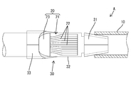
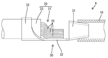
- the conductive member A includes a shape-retaining conductor 10, a flexible covered conductor 20, and a joint member 30 for electrically connecting the end of the shape-retaining conductor 10 and the end of the covered conductor 20. ing.
- the shape maintaining conductor 10 is made of aluminum or an aluminum alloy, and has a pipe shape with a circular cross section.
- the shape-retaining conductor 10 has shape-retaining properties that do not easily deform due to its own rigidity.
- the shape-retaining conductor 10 is bent into a predetermined shape and is routed along the vehicle floor.
- the coated conductor 20 includes a flexible conductor 21 (core wire) obtained by twisting a plurality of strands 22 and an insulating coating 23 that surrounds the flexible conductor 21 over the entire circumference.
- the strand 22 (flexible conductor 21) is made of aluminum or an aluminum alloy. That is, the flexible conductor 21 of the covered conductor 20 is the same material as that of the shape maintaining conductor 10.
- the insulating coating 23 is removed and the flexible conductor 21 is exposed.
- the joint member 30 is made of copper or a copper alloy (that is, a material different from the shape maintaining conductor 10 and the flexible conductor 21).
- the joint member 30 is formed by bending a plate material having a predetermined shape.
- the joint member 30 is a single component including a first connection portion 31, a second connection portion 32, and an insulation barrel portion 33.
- 1st connection part 31 is a means for adhering joint member 30 to shape maintenance conductor 10 so that conduction is possible.
- the first connecting portion 31 is formed by bending a fan-shaped portion of the plate material before bending so as to form a cylindrical shape.
- the first connecting portion 31 has a truncated cone shape whose axis is gradually reduced in the forward direction (that is, the direction of assembly to the shape-retaining conductor 10) with the axis line directed in the front-rear direction.
- the outer diameter of the first connection portion 31 the front end of the first connection portion 31 has a minimum dimension, and the rear end of the first connection portion 31 has a maximum dimension.
- the minimum outer diameter dimension of the first connection portion 31 is set to a dimension smaller than the inner diameter of the shape holding conductor 10, and the maximum outer diameter dimension of the first connection portion 31 is set to a dimension larger than the inner diameter of the shape holding conductor 10. Has been.
- the second connection portion 32 is a means for fixing the joint member 30 to the flexible conductor 21 of the coated conductor 20 so as to be conductive.
- the 2nd connection part 32 has comprised the flat plate shape which turned a plate
- the central portion in the width direction (left-right direction) at the front end edge of the second connection portion 32 is continuous with the rear end edge portion of the first connection portion 31.
- the width dimension of the second connection part 32 is set to be approximately the same as the maximum width dimension (maximum outer diameter dimension) of the first connection part 31.
- the insulation barrel portion 33 is a means for fixing the joint member 30 to the insulating coating 23 of the coated conductor 20.
- the second connecting portion 32 in a state before connecting the joint member 30 to the coated conductor 20 is a flat plate having a substantially square shape in plan view with the plate thickness direction directed in the vertical direction.
- the front end edge of the insulation barrel portion 33 is continuous with the rear end edge portion of the second connection portion 32.
- the width dimension of the insulation barrel portion 33 is larger than the width dimension of the second connection portion 32, and both end portions in the width direction of the insulation barrel portion 33 protrude outward from the outer edge of the second connection portion 32 in the width direction. Yes.
- the manufacturing process of the conductive member A of the present embodiment will be described.
- the insulating coating 23 is removed at the front end portion of the coated conductor 20 to expose the flexible conductor 21. Then, the strands 22 of the exposed portion of the flexible conductor 21 are untwisted so that the strands 22 are almost straight and bundled.
- the front end portion of the insulating coating 23 is placed on the insulation barrel portion 33, and the insulation barrel portion 33 is wound around the outer periphery of the insulating coating 23 by a crimping machine (not shown) and tightened.
- a crimping machine not shown
- the joint member 30 and the coated conductor 20 are transferred to the anvil of the ultrasonic welding apparatus (not shown). At this time, the exposed front end portion of the flexible conductor 21 is placed on the upper surface of the second connection portion 32. After placing on the anvil, a horn is pressed against the flexible conductor 21 from above, and the second connecting portion 32 and the flexible conductor 21 are pressed in the vertical direction (a direction parallel to the plate thickness direction of the second connecting portion 32). , Ultrasonically vibrate the horn.
- the contacting strands 22 are ultrasonically welded to each other, and to the second connection portion 32 and the second connection portion 32.
- the contacting wire 22 is ultrasonically welded.
- the strands 22 are brought into sliding contact with each other by ultrasonic vibration, and the strand 22 and the second connecting portion 32 are brought into sliding contact with each other by ultrasonic vibration, so that the oxide film on the surface of the strand 22 is scraped off.
- the strands 22 are fixed in a state where they are in contact with each other so as to be conductive, and the strand 22 and the second connecting portion 32 are fixed in a state where they are in contact with each other so as to be conductive.
- the covered conductor 20 and the joint member 30 are integrated.
- the first connecting portion 31 of the joint member 30 is inserted into the rear end portion of the shape maintaining conductor 10.
- the first connection portion 31 can be smoothly inserted into the shape retaining conductor 10. Since the outer peripheral surface of the first connection portion 31 is shaped so that the outer diameter gradually increases toward the rear end side, the outer peripheral surface of the first connection portion 31 is in the middle of the insertion of the shape maintaining conductor 10. It is in sliding contact with the inner peripheral edge of the rear end. By this sliding contact, the oxide film on the inner peripheral edge of the shape maintaining conductor 10 is scraped off.
- the contact portion is fixed by laser welding or the like. Thereby, the joint member 30 and the shape maintaining conductor 10 are connected, and the shape maintaining conductor 10 and the covered conductor 20 are connected through the joint member 30 so as to be conductive.
- the conductive member A of the present embodiment includes a shape-retaining conductor 10 having shape-retaining properties, a flexible conductor 21 having flexibility, and a joint member 30.
- the flexible conductor 21 constitutes the coated conductor 20 by being integrated with an insulating coating 23 surrounding the flexible conductor 21.
- the joint member 30 is formed with a first connection portion 31 fixed to the shape maintaining conductor 10 and a flat second connection portion 32 fixed to the flexible conductor 21. Since the flexible conductor 21 can be stacked on the second connection portion 32 having a flat plate shape, the flexible conductor 21 and the second connection portion 32 can be fixed by ultrasonic welding or the like. Thereby, in this embodiment, ultrasonic welding is realized.
- the flexible conductor 21 is a stranded wire made of an aluminum or aluminum alloy strand 22, but the strands 22 rub against each other due to vibration in the ultrasonic welding process, and at the same time, the stranded wire and the second connecting portion 32 rub against each other. Therefore, the oxide film of the strand 22 is removed. Therefore, the contact reliability is high as compared with the fixing method in which the flexible conductor 21 and the second connection portion 32 are simply pressurized.
- the joint member 30 is formed with an insulation barrel portion 33 fixed to the outer periphery of the insulating coating 23. According to this configuration, the joint member 30 and the covered conductor 20 can be reliably connected.
- the shape retaining conductor 10 has a pipe shape and the first connection portion 31 is inserted into the shape retaining conductor 10, the shape retaining conductor 10 is outside the connection portion between the shape retaining conductor 10 and the first connection portion 31.
- the diameter dimension can be accommodated in the same dimension as the outer diameter of the shape retaining conductor 10.
- the 1st connection part 31 has comprised the truncated cone shape diameter-reduced toward the insertion direction to the shape maintenance conductor 10, it is one kind of joint with respect to the multiple types of shape maintenance conductor 10 from which an internal diameter differs.
- the member 30 can be applied.
- the present invention is not limited to the embodiments described with reference to the above description and drawings.
- the following embodiments are also included in the technical scope of the present invention.
- the shape maintaining conductor is made of aluminum or aluminum alloy, but the material of the shape holding conductor may be a material other than aluminum or aluminum alloy (copper, copper alloy, etc.).
- the shape maintaining conductor has a pipe shape, but the shape maintaining conductor may have a solid rod shape.
- the flexible conductor is made of aluminum or aluminum alloy, but the material of the flexible conductor may be a material other than aluminum or aluminum alloy (copper, copper alloy, etc.).
- the flexible conductor is a stranded wire, but the flexible conductor may be a single core wire.
- the joint member is made of copper or copper alloy, but the joint member may be made of a material other than copper or copper alloy (for example, aluminum or aluminum alloy).
- the insulation barrel part was formed in the joint member, the joint member may not have an insulation barrel part.
- the shape maintaining conductor and the joint member are made of different materials, but the shape maintaining conductor and the joint member may be made of the same material.
- the joint member and the flexible conductor of the coated conductor are made of different materials in the above embodiment, the joint member and the flexible conductor may be made of the same material.
- the shape maintaining conductor and the flexible conductor of the coated conductor are made of the same material, but the shape holding conductor and the flexible conductor may be made of different materials.
- the first connection portion is accommodated in the shape maintaining conductor, but the first connection portion may be fixed to the outer periphery of the shape maintaining conductor.
- the first connection portion has a truncated cone shape whose diameter is reduced toward the front in the insertion direction into the pipe, but the first connection portion has a substantially cylindrical shape with a constant diameter dimension. It may be done.
- the shape maintaining conductor and the first connecting portion are fixed by laser welding, but the shape maintaining conductor and the first connecting portion may be fixed by a method other than laser welding.
- the cross-sectional shape of the shape-retaining conductor is circular, but the cross-sectional shape of the shape-retaining conductor may be non-circular.
- the flexible conductor is integrated with the insulating coating that surrounds the flexible conductor to constitute the coated conductor, but the flexible conductor may not be surrounded by the insulating coating.
- a ... conductive member 10 ... shape retaining conductor 20 ... coated conductor 21 ... flexible conductor 23 ... insulating coating 30 ... joint member 31 ... first connecting portion 32 ... second connecting portion 33 ... insulation barrel portion
Landscapes
- Connections Effected By Soldering, Adhesion, Or Permanent Deformation (AREA)
- Insulated Conductors (AREA)
Abstract
Afin d'améliorer la fiabilité de contact, l'invention concerne un élément conducteur (A) qui est pourvu : d'un conducteur à conservation de forme (10) qui possède des propriétés de conservation de forme ; d'un conducteur souple (21) souple ; et d'un élément d'assemblage (30) dans lequel une première unité de connexion (31), fixée au conducteur à conservation de forme (10), et une seconde unité de connexion (32), ayant une forme plate et fixée au conducteur souple (21), sont formées. Étant donné que le conducteur souple (21) peut être placé sur la seconde unité de connexion plate (32), il est possible de fixer l'un à l'autre le conducteur souple (21) et la seconde unité de connexion (32) par soudage par ultrasons. Étant donné qu'un film d'oxyde est éliminé par vibration à l'étape de soudage par ultrasons, une plus haute fiabilité de contact est obtenue par comparaison au cas d'un procédé de fixation consistant seulement à appliquer une pression au conducteur souple (21) et à la seconde unité de connexion (32).
Applications Claiming Priority (2)
| Application Number | Priority Date | Filing Date | Title |
|---|---|---|---|
| JP2016086774A JP2017199458A (ja) | 2016-04-25 | 2016-04-25 | 導電部材 |
| JP2016-086774 | 2016-04-25 |
Publications (1)
| Publication Number | Publication Date |
|---|---|
| WO2017187955A1 true WO2017187955A1 (fr) | 2017-11-02 |
Family
ID=60160404
Family Applications (1)
| Application Number | Title | Priority Date | Filing Date |
|---|---|---|---|
| PCT/JP2017/014742 Ceased WO2017187955A1 (fr) | 2016-04-25 | 2017-04-11 | Élément conducteur |
Country Status (2)
| Country | Link |
|---|---|
| JP (1) | JP2017199458A (fr) |
| WO (1) | WO2017187955A1 (fr) |
Citations (5)
| Publication number | Priority date | Publication date | Assignee | Title |
|---|---|---|---|---|
| JPS4819988U (fr) * | 1971-07-15 | 1973-03-07 | ||
| JPS6210977U (fr) * | 1985-07-02 | 1987-01-23 | ||
| JP2004241246A (ja) * | 2003-02-05 | 2004-08-26 | Sumitomo Wiring Syst Ltd | 端子金具及びコネクタ |
| JP2015088251A (ja) * | 2013-10-28 | 2015-05-07 | 矢崎総業株式会社 | 回路導体、接続構造、及び回路導体の製造方法 |
| JP2015135742A (ja) * | 2014-01-16 | 2015-07-27 | 住友電装株式会社 | 端子および該端子の電線接続方法 |
-
2016
- 2016-04-25 JP JP2016086774A patent/JP2017199458A/ja active Pending
-
2017
- 2017-04-11 WO PCT/JP2017/014742 patent/WO2017187955A1/fr not_active Ceased
Patent Citations (5)
| Publication number | Priority date | Publication date | Assignee | Title |
|---|---|---|---|---|
| JPS4819988U (fr) * | 1971-07-15 | 1973-03-07 | ||
| JPS6210977U (fr) * | 1985-07-02 | 1987-01-23 | ||
| JP2004241246A (ja) * | 2003-02-05 | 2004-08-26 | Sumitomo Wiring Syst Ltd | 端子金具及びコネクタ |
| JP2015088251A (ja) * | 2013-10-28 | 2015-05-07 | 矢崎総業株式会社 | 回路導体、接続構造、及び回路導体の製造方法 |
| JP2015135742A (ja) * | 2014-01-16 | 2015-07-27 | 住友電装株式会社 | 端子および該端子の電線接続方法 |
Also Published As
| Publication number | Publication date |
|---|---|
| JP2017199458A (ja) | 2017-11-02 |
Similar Documents
| Publication | Publication Date | Title |
|---|---|---|
| JP5235369B2 (ja) | ワイヤーハーネスおよびその製造方法ならびに絶縁電線の接続方法 | |
| US9444154B2 (en) | Terminal fitting-equipped conductor | |
| CN103688410A (zh) | 电线连接方法 | |
| WO2011126115A1 (fr) | Procédé de connexion de fil électrique et faisceau électrique | |
| JP2014211953A (ja) | 電線の接続方法,接続装置 | |
| JP2016001551A (ja) | 被覆電線および圧着端子付き電線 | |
| CN109861010A (zh) | 端子连接方法和端子 | |
| US10038292B2 (en) | Method for connecting insulated wires | |
| CN105990713A (zh) | 具有连接端子的电线和用于制造该电线的方法 | |
| JP6774627B2 (ja) | 電線の接合構造及びワイヤハーネス | |
| JP2019200997A (ja) | 機器用配線集合体 | |
| JP7022360B2 (ja) | 機器用配線集合体 | |
| JP6719873B2 (ja) | 車両用の機器用配線集合体 | |
| JP6013417B2 (ja) | 被覆電線の接合方法 | |
| JP5223798B2 (ja) | 電線連結構造及びその電線連結構造を有する車両用導電路 | |
| WO2017175701A1 (fr) | Faisceau électrique | |
| JP2017216102A (ja) | 導通接続部材 | |
| CN108886205A (zh) | 导体的连接结构以及线束 | |
| JP2017199461A (ja) | 導電部材 | |
| JP2017199458A (ja) | 導電部材 | |
| JP5445805B2 (ja) | 電線連結構造及びその電線連結構造を有する車両用導電路 | |
| JP6276820B2 (ja) | 被覆電線の接合方法 | |
| JP6556512B2 (ja) | ワイヤハーネス | |
| WO2019181633A1 (fr) | Structure de connexion de fils électriques, et procédé de production de harnais | |
| JP7362425B2 (ja) | 配索材 |
Legal Events
| Date | Code | Title | Description |
|---|---|---|---|
| NENP | Non-entry into the national phase |
Ref country code: DE |
|
| 121 | Ep: the epo has been informed by wipo that ep was designated in this application |
Ref document number: 17789242 Country of ref document: EP Kind code of ref document: A1 |
|
| 122 | Ep: pct application non-entry in european phase |
Ref document number: 17789242 Country of ref document: EP Kind code of ref document: A1 |