WO2017188207A1 - Structure de cadre de colonne pour maison préfabriquée - Google Patents
Structure de cadre de colonne pour maison préfabriquée Download PDFInfo
- Publication number
- WO2017188207A1 WO2017188207A1 PCT/JP2017/016266 JP2017016266W WO2017188207A1 WO 2017188207 A1 WO2017188207 A1 WO 2017188207A1 JP 2017016266 W JP2017016266 W JP 2017016266W WO 2017188207 A1 WO2017188207 A1 WO 2017188207A1
- Authority
- WO
- WIPO (PCT)
- Prior art keywords
- column frame
- unit house
- eaves
- roof panel
- frame
- Prior art date
- Legal status (The legal status is an assumption and is not a legal conclusion. Google has not performed a legal analysis and makes no representation as to the accuracy of the status listed.)
- Ceased
Links
Images


Classifications
-
- E—FIXED CONSTRUCTIONS
- E04—BUILDING
- E04B—GENERAL BUILDING CONSTRUCTIONS; WALLS, e.g. PARTITIONS; ROOFS; FLOORS; CEILINGS; INSULATION OR OTHER PROTECTION OF BUILDINGS
- E04B1/00—Constructions in general; Structures which are not restricted either to walls, e.g. partitions, or floors or ceilings or roofs
- E04B1/343—Structures characterised by movable, separable, or collapsible parts, e.g. for transport
- E04B1/344—Structures characterised by movable, separable, or collapsible parts, e.g. for transport with hinged parts
- E04B1/3445—Structures characterised by movable, separable, or collapsible parts, e.g. for transport with hinged parts foldable in a flat stack of parallel panels
-
- E—FIXED CONSTRUCTIONS
- E04—BUILDING
- E04B—GENERAL BUILDING CONSTRUCTIONS; WALLS, e.g. PARTITIONS; ROOFS; FLOORS; CEILINGS; INSULATION OR OTHER PROTECTION OF BUILDINGS
- E04B1/00—Constructions in general; Structures which are not restricted either to walls, e.g. partitions, or floors or ceilings or roofs
- E04B1/343—Structures characterised by movable, separable, or collapsible parts, e.g. for transport
- E04B1/344—Structures characterised by movable, separable, or collapsible parts, e.g. for transport with hinged parts
- E04B1/3441—Structures characterised by movable, separable, or collapsible parts, e.g. for transport with hinged parts with articulated bar-shaped elements
-
- E—FIXED CONSTRUCTIONS
- E04—BUILDING
- E04D—ROOF COVERINGS; SKY-LIGHTS; GUTTERS; ROOF-WORKING TOOLS
- E04D13/00—Special arrangements or devices in connection with roof coverings; Protection against birds; Roof drainage ; Sky-lights
- E04D13/04—Roof drainage; Drainage fittings in flat roofs, balconies or the like
- E04D13/064—Gutters
-
- E—FIXED CONSTRUCTIONS
- E04—BUILDING
- E04H—BUILDINGS OR LIKE STRUCTURES FOR PARTICULAR PURPOSES; SWIMMING OR SPLASH BATHS OR POOLS; MASTS; FENCING; TENTS OR CANOPIES, IN GENERAL
- E04H1/00—Buildings or groups of buildings for dwelling or office purposes; General layout, e.g. modular co-ordination or staggered storeys
- E04H1/12—Small buildings or other erections for limited occupation, erected in the open air or arranged in buildings, e.g. kiosks, waiting shelters for bus stops or for filling stations, roofs for railway platforms, watchmen's huts or dressing cubicles
- E04H1/1205—Small buildings erected in the open air
-
- E—FIXED CONSTRUCTIONS
- E04—BUILDING
- E04H—BUILDINGS OR LIKE STRUCTURES FOR PARTICULAR PURPOSES; SWIMMING OR SPLASH BATHS OR POOLS; MASTS; FENCING; TENTS OR CANOPIES, IN GENERAL
- E04H1/00—Buildings or groups of buildings for dwelling or office purposes; General layout, e.g. modular co-ordination or staggered storeys
- E04H1/12—Small buildings or other erections for limited occupation, erected in the open air or arranged in buildings, e.g. kiosks, waiting shelters for bus stops or for filling stations, roofs for railway platforms, watchmen's huts or dressing cubicles
- E04H2001/1283—Small buildings of the ISO containers type
Definitions
- the present invention relates to a column frame structure for a unit house that is produced in a factory and assembled locally, and relates to a column frame structure for a unit house that can improve transportation efficiency and design and can maintain waterproofness.
- Patent Document 1 The folding unit house described in Patent Document 1 was previously proposed by the applicant of the present invention, and a column frame or a wall panel is folded between a floor panel and a roof panel, and is transported in a folded state. It is assembled with.
- the unit house described in Patent Document 2 is provided with eaves at the end of the roof side of the house.
- the eaves are constructed so that the rainwater received on the roof is received by the fence and drained along the chain.
- the unit house described in Patent Document 1 has a structure in which the eaves on the wife side protrude outward from the pillar frame and the side wall panel during assembly. For this reason, when the house is folded, the eaves portion of the roof panel protrudes greatly, and this eaves portion has an inconvenience during loading.
- the eaves are designed to increase the waterproof property by providing them on the protruding eaves, if the eaves are not provided so that they will not protrude, There is a possibility that the waterproofness of the battery deteriorates.
- the present invention was created to solve the above-described problems, and aims to provide a column frame structure for a unit house that improves transport efficiency and maintains a waterproof appearance and a good appearance. Is.
- the first means in the present invention is a unit house in which the column frame 20 is foldably mounted on the floor panel 40 and the roof panel 10 is loaded on the column frame 20 and transported.
- the outer surface of the end side of the roof panel 10 is configured not to protrude from the outer side of the end of the pillar frame 20 erected, and from the end of the end of the roof panel 10
- the eaves rod 50 is installed downward, and the eaves rod 50 is configured not to protrude outward from the outer side surface of the pillar frame 20 on the wife side.
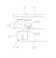
- the second means is provided with a top plate 21 in contact with the lower surface of the end face of the roof panel 10 at the upper end of the column frame 20, and a recess 21A is formed in a portion of the top plate 21 in contact with the eaves 50.
- the outer side surface of the eaves bowl 50 that overlaps the concave portion and the outer side surface of the pillar frame 20 on the wife side are configured to coincide with each other.
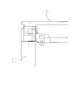
- the third means is that the end beam 22 disposed along the end side of the roof panel 10 is provided at the upper end of the column frame 20, and the end beam 22 swings together with the column frame 20. It is comprised so that the upper end part of the end beam 22 may overlap with the end surface on the end side of the roof beam 11 that supports the roof panel 10 when the unit house P is assembled.
- the column frame 20 includes a connection fixing body 61 fixed to the end of the roof beam 11, and a connection fixing body 61 swingably connected to the upper end portion side of the column frame 20.
- the oscillating fixed body 62 is provided with an insertion hole 62A through which a connecting pin 61A projecting from the side surface of the linking fixed body 61 is inserted by a connecting tool 60 composed of the oscillating fixed body 62 fixed to the side surface.
- the insertion hole 62A is formed in a long hole shape so that the upper end portion of the column frame 20 erected at the time of assembling the unit house P moves in the vertical direction.
- the outer surface of the end portion of the roof panel 10 on the end side of the roof panel 10 is configured not to protrude from the outer side surface of the column frame 20 standing upright. At times, the eaves portion of the roof panel 10 does not have to protrude greatly, so that extremely efficient loading is possible.
- the eaves rod 50 is installed from the end of the end of the roof panel 10 to the lower side, and the eaves 50 is configured not to protrude outward from the outer side of the end of the column frame 20. It has become difficult to see. As a result, it has become possible to adapt to use as an eye-catching high-quality building such as a store, office, or showroom.
- the top plate 21 is provided at the upper end of the column frame 20 so as to contact the lower surface of the end of the end of the roof panel 10.
- the outer surface of the eaves bowl 50 is configured to overlap the concave portion and the outer side surface of the pillar frame 20 on the wife side. So it can provide an excellent appearance design.
- the cross beam 22 disposed along the end of the roof panel 10 is provided at the upper end of the column frame 20 so that the cross beam 22 swings together with the column frame 20. Since the upper end portion of the span beam 22 overlaps the lower surface of the end side of the roof beam 11 that supports the roof panel 10 when the unit house P is assembled, the lower surface of the roof beam 11 has the lower end of the end beam 22. Has a structure that fits. Therefore, waterproofness can be improved even with a configuration in which the outer surface of the roof panel 10 does not protrude from the outer surface on the wife side of the column frame 20 erected.
- the insertion hole 62 ⁇ / b> A of the connector 60 is formed in a long hole shape so that the upper end portion of the column frame 20 erected at the time of assembling the unit house P moves in the vertical direction. Can be lifted further upward from the standing state and can be brought into contact with the lower surface of the roof panel 10. As a result, it is possible to improve the fit of the column frame 20 during assembly while compactly storing the column frame 20 during folding.
- the initial purpose of improving the transportation efficiency and improving the appearance of the appearance while maintaining the waterproof property has been achieved.
- the present invention is a unit house P produced at a factory and assembled locally (see FIG. 1).
- the unit house P is folded and stacked on the floor panel 40, and further transported with the roof panel 10 stacked on the column frame 20 (see FIG. 2).
- the roof panel 10 is lifted locally (see FIG. 3)
- the column frame 20 gradually expands, and the column frame 20 is erected between the roof panel 10 and the floor panel 40 during assembly (see FIG. 3). 4).
- the outer side surface of the end of the roof panel 10 is configured not to protrude from the outer side of the standing column frame 20 (see FIG. 7). Furthermore, the eaves rod 50 is installed from the end of the end of the roof panel 10 to the lower side so that the eaves 50 does not protrude outwardly from the outer side surface of the column frame 20 (see FIG. 1). ).
- a top plate 21 is provided at the upper end of the column frame 20.
- the top plate 21 is a portion that contacts the lower surface of the end portion of the roof panel 10, and in particular, a recess 21 ⁇ / b> A is formed in a portion that contacts the eaves 50 of the top plate 21.
- the recess 21A is formed so that the eaves hook 50 attached to the end of the roof panel 10 on the end side overlaps. That is, when the eaves 50 is wound so as to overlap with the concave portion 21A of the top plate 21, the outer surface of the eaves 50 and the outer surface of the pillar frame 20 on the wife side coincide with each other (see FIG. 1). .
- the illustrated column frame 20 is provided with a beam 22 disposed along the wife side of the roof panel 10, and the beam 22 is configured to swing together with the column frame 20 (see FIG. 6).
- the upper end portion of the end beam 22 is configured to overlap the lower surface of the end surface of the roof beam 11 that supports the roof panel 10 (see FIG. 9).
- connection tool 60 includes a connection fixing body 61 and a swing fixing body 62. That is, the connection fixing body 61 is a member fixed to the end of the roof beam 11 and includes a connection pin 61A.
- the swinging fixed body 62 is a member that is swingably connected to the connecting fixed body 61, and is fixed to the side surface on the upper end side of the column frame 20 (see FIG. 6).
- the swing fixed body 62 is formed with an insertion hole 62A through which the connection pin 61A of the connection fixed body 61 is inserted.
- the insertion hole 62A By forming the insertion hole 62A into a long hole shape, the column frame 20 is moved in a swinging manner. And slide movement (see FIGS. 6 and 7).
- the column frame 20 swings around the connection fixing body 61 of the connection tool 60 (see FIG. 6).
- the upright end of the pillar frame 20 is configured to slide in the vertical direction (see FIGS. 7 and 8).
- the pillar frame 20 is formed in a long hole shape along the longitudinal direction, and the pillar frame 20 is provided so as to slide in the vertical direction along the insertion hole 62A (see FIG. 7).
- the lifted roof panel 10 is lowered so that the column frame 20 is relatively slid.
- the top plate 21 of the column frame 20 overlaps with the bottom surface of the roof panel 10 (see FIG. 8).
- the waterproof property can be enhanced.
- the insertion hole 62A can slide and move the position of the column frame 20 horizontally along the insertion hole 62A in a state in which the column frame 20 is folded, so that compact storage is possible (see FIG. 5).
- the configuration of the unit house P of the present invention is not limited to the illustrated example, and the configuration and shape of the roof panel 10, the column frame 20, the eaves 50, and the like can be arbitrarily changed. In addition, design changes can be freely made without changing the gist of the present invention.
Landscapes
- Engineering & Computer Science (AREA)
- Architecture (AREA)
- Civil Engineering (AREA)
- Structural Engineering (AREA)
- Physics & Mathematics (AREA)
- Electromagnetism (AREA)
- Residential Or Office Buildings (AREA)
- Load-Bearing And Curtain Walls (AREA)
Abstract
Priority Applications (6)
| Application Number | Priority Date | Filing Date | Title |
|---|---|---|---|
| MYPI2018703680A MY197292A (en) | 2016-04-28 | 2017-04-25 | Column frame structure for prefabricated house |
| SG11201808875WA SG11201808875WA (en) | 2016-04-28 | 2017-04-25 | Column frame structure for prefabricated house |
| US16/097,210 US10774520B2 (en) | 2016-04-28 | 2017-04-25 | Column frame structure for prefabricated house |
| CA3022211A CA3022211C (fr) | 2016-04-28 | 2017-04-25 | Structure de cadre de colonne pour maison prefabriquee |
| AU2017254989A AU2017254989B2 (en) | 2016-04-28 | 2017-04-25 | Column frame structure for prefabricated house |
| PH12018502172A PH12018502172A1 (en) | 2016-04-28 | 2018-10-10 | Column frame structure for prefabricated house |
Applications Claiming Priority (2)
| Application Number | Priority Date | Filing Date | Title |
|---|---|---|---|
| JP2016-001956U | 2016-04-28 | ||
| JP2016001956U JP3205191U (ja) | 2016-04-28 | 2016-04-28 | ユニットハウス用柱フレーム構造 |
Publications (1)
| Publication Number | Publication Date |
|---|---|
| WO2017188207A1 true WO2017188207A1 (fr) | 2017-11-02 |
Family
ID=56329329
Family Applications (1)
| Application Number | Title | Priority Date | Filing Date |
|---|---|---|---|
| PCT/JP2017/016266 Ceased WO2017188207A1 (fr) | 2016-04-28 | 2017-04-25 | Structure de cadre de colonne pour maison préfabriquée |
Country Status (8)
| Country | Link |
|---|---|
| US (1) | US10774520B2 (fr) |
| JP (1) | JP3205191U (fr) |
| AU (1) | AU2017254989B2 (fr) |
| CA (1) | CA3022211C (fr) |
| MY (1) | MY197292A (fr) |
| PH (1) | PH12018502172A1 (fr) |
| SG (1) | SG11201808875WA (fr) |
| WO (1) | WO2017188207A1 (fr) |
Families Citing this family (6)
| Publication number | Priority date | Publication date | Assignee | Title |
|---|---|---|---|---|
| JP3205191U (ja) * | 2016-04-28 | 2016-07-07 | 三協フロンテア株式会社 | ユニットハウス用柱フレーム構造 |
| CN210127679U (zh) * | 2019-04-24 | 2020-03-06 | 汉尔姆建筑科技有限公司 | 一种小型移动空间 |
| CA3207130A1 (fr) | 2020-12-31 | 2022-07-07 | Mitek Holdings, Inc. | Modules de construction a assemblage rapide et procedes d'utilisation |
| CN112878498A (zh) * | 2021-03-06 | 2021-06-01 | 安徽虎龙建筑工程有限公司 | 一种景点用的可折叠a字形房屋 |
| JP7308331B1 (ja) | 2022-05-10 | 2023-07-13 | 三協フロンテア株式会社 | ユニットハウス用配管構造 |
| AU2024339205B1 (en) * | 2023-12-01 | 2025-06-19 | Weitao SHI | Modular building platform and assembly method thereof |
Citations (6)
| Publication number | Priority date | Publication date | Assignee | Title |
|---|---|---|---|---|
| JPS60148402U (ja) * | 1984-03-14 | 1985-10-02 | 四国化成工業株式会社 | 物置 |
| JPH0810084Y2 (ja) * | 1990-06-05 | 1996-03-27 | 株式会社淀川製鋼所 | 組立家屋における柱と上枠との接続構造 |
| JP2602842Y2 (ja) * | 1992-01-23 | 2000-01-31 | 富士重工業株式会社 | 折畳式ユニットハウス |
| JP2005248547A (ja) * | 2004-03-04 | 2005-09-15 | Fuji Heavy Ind Ltd | 折り畳み式ユニットハウス |
| US20080083189A1 (en) * | 2006-08-16 | 2008-04-10 | Les Ateliers Bolduc Et Freres Inc. | Stackable building structure frame |
| JP2016023420A (ja) * | 2014-07-16 | 2016-02-08 | 不二サッシ株式会社 | 折り畳み式組立家屋 |
Family Cites Families (40)
| Publication number | Priority date | Publication date | Assignee | Title |
|---|---|---|---|---|
| US2047388A (en) * | 1933-09-14 | 1936-07-14 | Western Electric Co | Table |
| US2395691A (en) * | 1942-05-25 | 1946-02-26 | William B Stout | Building with folding walls |
| US2549816A (en) * | 1946-04-24 | 1951-04-24 | Hugh B Johnson | Portable shelter |
| US2784687A (en) * | 1951-09-20 | 1957-03-12 | United States Steel Corp | Sheet-metal gutter board |
| US2642825A (en) * | 1951-11-01 | 1953-06-23 | Copco Steel And Engineering Co | Foldable and compactable truss and stud support |
| NL271076A (fr) * | 1960-11-07 | |||
| US3348344A (en) * | 1964-02-19 | 1967-10-24 | Tatevossian Leon | Transportable building contruction with an extendable body structure |
| US3638373A (en) * | 1969-07-31 | 1972-02-01 | Chapman & Miller Architects | Collapsable roof for preassembled building |
| US3712006A (en) * | 1971-04-05 | 1973-01-23 | K Bea | Foldable building construction of roof and wall sections |
| US3971185A (en) * | 1971-09-09 | 1976-07-27 | Hendrich John H | Method of erecting a foldable building module |
| US3863419A (en) * | 1971-09-09 | 1975-02-04 | John H Hendrich | Method of constructing a foldable building |
| US3968618A (en) * | 1974-05-31 | 1976-07-13 | Johnson Delp W | Method of constructing a foldable building with beam roof and rigid frame |
| US4170852A (en) * | 1977-11-28 | 1979-10-16 | Danis Industries Corporation | Articulated prefabricated modular building and method of erecting the same |
| US4327532A (en) * | 1980-07-18 | 1982-05-04 | Kawneer Company, Inc. | Adjustable angle eave apparatus |
| US4464868A (en) * | 1981-05-18 | 1984-08-14 | Howroyd Lawrence H | Building construction |
| IT1192455B (it) * | 1982-06-18 | 1988-04-13 | Giovanna Maria Fagnoni | Struttura trasportabile per formare abitazione od altro,adatta per interventi immediati |
| JPS61184054U (fr) | 1985-05-08 | 1986-11-17 | ||
| IT1201296B (it) * | 1985-05-21 | 1989-01-27 | Edil Pro Spa | Struttura trasportabile perfezionata,atta a costituire abitazioni od altri ambienti |
| US4891919A (en) * | 1986-12-10 | 1990-01-09 | Palibroda James W | Containerized transportable house |
| NL8702908A (nl) * | 1987-12-03 | 1989-07-03 | D3Bn Adviesbureau Civ Ing | Overkappingswerkwijze en -inrichting. |
| US5426822A (en) * | 1988-11-23 | 1995-06-27 | Weir; Richard L. | Hinge structure |
| US5553961A (en) * | 1994-11-02 | 1996-09-10 | Mitek Holdings, Inc. | Hinge and hinge joint for hingedly connecting structural frame members |
| GB9503228D0 (en) * | 1995-02-18 | 1995-04-05 | Dyer David C | Modular structures and seals therefor |
| US5983577A (en) * | 1997-02-19 | 1999-11-16 | Erecta Shelters, Inc. | Light weight pre-engineered prefabricated modular building system |
| JP3058646U (ja) | 1998-10-22 | 1999-06-22 | 三協フロンテア株式会社 | 折畳みユニットハウス |
| US6463705B1 (en) * | 1998-11-20 | 2002-10-15 | Oakwood Homes Corporation | Container for prefabricated transportable buildings |
| US6173726B1 (en) * | 1998-12-09 | 2001-01-16 | Fiskars Inc. | Erectable shelter including a collapsible truss |
| US6434895B1 (en) * | 1999-09-09 | 2002-08-20 | Bendon, L.L.C. | Foldable trailerable building |
| US6401422B1 (en) * | 2000-02-04 | 2002-06-11 | Mitek Holdings, Inc. | Hinge and hinge joint for structural frame members |
| US6519900B1 (en) * | 2000-06-30 | 2003-02-18 | Turnkey Schools Of America | Modular school building system |
| US7418802B2 (en) * | 2005-09-09 | 2008-09-02 | Gichner Systems Group, Inc. | Expandable shelter system |
| US7677009B2 (en) * | 2007-02-02 | 2010-03-16 | Nova Chemicals Inc. | Roof truss system |
| US9416528B2 (en) * | 2007-07-12 | 2016-08-16 | Schaffert Manufacturing Company, Inc. | Folding shed with portable feature |
| US7918054B2 (en) * | 2008-02-25 | 2011-04-05 | Gp Innovative Concepts, Llc | Roofing bracket and system |
| US20100024351A1 (en) * | 2008-07-29 | 2010-02-04 | Green Horizon Manufacturing Llc | Method of deploying and redeploying a prefabricated structure |
| US8381454B1 (en) * | 2009-01-23 | 2013-02-26 | Markus R. Robinson | Segmented, elongated, expandable, 4-season, double-walled, low-cost, rigid extruded plastic panel structures |
| US20110197521A1 (en) * | 2010-02-16 | 2011-08-18 | Michael Robert Courtney | System of modular construction and assembled structure |
| WO2014169320A1 (fr) * | 2013-04-15 | 2014-10-23 | Dynon Matthew | Module de construction pliable préfabriqué |
| US20150136283A1 (en) * | 2013-11-18 | 2015-05-21 | Michael Rensch | Roofing cover |
| JP3205191U (ja) * | 2016-04-28 | 2016-07-07 | 三協フロンテア株式会社 | ユニットハウス用柱フレーム構造 |
-
2016
- 2016-04-28 JP JP2016001956U patent/JP3205191U/ja not_active Expired - Lifetime
-
2017
- 2017-04-25 CA CA3022211A patent/CA3022211C/fr active Active
- 2017-04-25 SG SG11201808875WA patent/SG11201808875WA/en unknown
- 2017-04-25 US US16/097,210 patent/US10774520B2/en active Active
- 2017-04-25 WO PCT/JP2017/016266 patent/WO2017188207A1/fr not_active Ceased
- 2017-04-25 MY MYPI2018703680A patent/MY197292A/en unknown
- 2017-04-25 AU AU2017254989A patent/AU2017254989B2/en active Active
-
2018
- 2018-10-10 PH PH12018502172A patent/PH12018502172A1/en unknown
Patent Citations (6)
| Publication number | Priority date | Publication date | Assignee | Title |
|---|---|---|---|---|
| JPS60148402U (ja) * | 1984-03-14 | 1985-10-02 | 四国化成工業株式会社 | 物置 |
| JPH0810084Y2 (ja) * | 1990-06-05 | 1996-03-27 | 株式会社淀川製鋼所 | 組立家屋における柱と上枠との接続構造 |
| JP2602842Y2 (ja) * | 1992-01-23 | 2000-01-31 | 富士重工業株式会社 | 折畳式ユニットハウス |
| JP2005248547A (ja) * | 2004-03-04 | 2005-09-15 | Fuji Heavy Ind Ltd | 折り畳み式ユニットハウス |
| US20080083189A1 (en) * | 2006-08-16 | 2008-04-10 | Les Ateliers Bolduc Et Freres Inc. | Stackable building structure frame |
| JP2016023420A (ja) * | 2014-07-16 | 2016-02-08 | 不二サッシ株式会社 | 折り畳み式組立家屋 |
Also Published As
| Publication number | Publication date |
|---|---|
| PH12018502172A1 (en) | 2019-08-19 |
| JP3205191U (ja) | 2016-07-07 |
| US20190112801A1 (en) | 2019-04-18 |
| AU2017254989A1 (en) | 2018-11-29 |
| SG11201808875WA (en) | 2018-11-29 |
| AU2017254989B2 (en) | 2019-09-26 |
| MY197292A (en) | 2023-06-12 |
| CA3022211C (fr) | 2020-12-08 |
| CA3022211A1 (fr) | 2017-11-02 |
| US10774520B2 (en) | 2020-09-15 |
Similar Documents
| Publication | Publication Date | Title |
|---|---|---|
| JP3205191U (ja) | ユニットハウス用柱フレーム構造 | |
| US7631460B2 (en) | Transportable building | |
| US10687510B2 (en) | Easy-to-fold and easy-to-assemble box and pet house using the box | |
| JP5690644B2 (ja) | 簡易建物 | |
| KR20150072650A (ko) | 프리패브리케이션 주거공간 확장 유닛을 이용한 아파트의 주거공간 확장 공법 | |
| KR20190087840A (ko) | 공간 가변형 가건물 | |
| CN111677341A (zh) | 可变形集装箱房屋 | |
| KR200439092Y1 (ko) | 절첩이 용이한 조립식 탈의실 | |
| JP2012241408A (ja) | 組み立て式テント | |
| KR101310641B1 (ko) | 접이식 벽체 | |
| CN201730385U (zh) | 整体折叠式帐篷架 | |
| JP4819499B2 (ja) | 寄棟状折畳式テント | |
| KR101262079B1 (ko) | 에어컨 실외기 설치대 | |
| CN202248272U (zh) | 一种可伸缩的组合房屋箱 | |
| CN201810028U (zh) | 一种帐篷架 | |
| CN201276758Y (zh) | 一种组合式房屋的梁架结构 | |
| CN109057007B (zh) | 一种铝型材制备的双级顶中式结构框架房 | |
| CN201107960Y (zh) | 宠物房固定结构 | |
| KR20210097853A (ko) | 골조없이 단일체로 된 접이식 연등 | |
| JP2603340Y2 (ja) | ユニット建物 | |
| CN202284404U (zh) | 折叠式帐篷架 | |
| JPH0743297Y2 (ja) | 外壁の構造 | |
| JP3150257U (ja) | コンテナ | |
| CN201763043U (zh) | 防水快建帐篷 | |
| JPS63147035A (ja) | 組立式家屋 |
Legal Events
| Date | Code | Title | Description |
|---|---|---|---|
| ENP | Entry into the national phase |
Ref document number: 3022211 Country of ref document: CA |
|
| NENP | Non-entry into the national phase |
Ref country code: DE |
|
| 121 | Ep: the epo has been informed by wipo that ep was designated in this application |
Ref document number: 17789489 Country of ref document: EP Kind code of ref document: A1 |
|
| ENP | Entry into the national phase |
Ref document number: 2017254989 Country of ref document: AU Date of ref document: 20170425 Kind code of ref document: A |
|
| 122 | Ep: pct application non-entry in european phase |
Ref document number: 17789489 Country of ref document: EP Kind code of ref document: A1 |