WO2017188399A1 - Dispositif de soudage par points, procédé de soudage par points et structure de raccord - Google Patents
Dispositif de soudage par points, procédé de soudage par points et structure de raccord Download PDFInfo
- Publication number
- WO2017188399A1 WO2017188399A1 PCT/JP2017/016816 JP2017016816W WO2017188399A1 WO 2017188399 A1 WO2017188399 A1 WO 2017188399A1 JP 2017016816 W JP2017016816 W JP 2017016816W WO 2017188399 A1 WO2017188399 A1 WO 2017188399A1
- Authority
- WO
- WIPO (PCT)
- Prior art keywords
- joint
- joining
- friction stir
- spot
- resistance spot
- Prior art date
- Legal status (The legal status is an assumption and is not a legal conclusion. Google has not performed a legal analysis and makes no representation as to the accuracy of the status listed.)
- Ceased
Links
Images


Classifications
-
- B—PERFORMING OPERATIONS; TRANSPORTING
- B23—MACHINE TOOLS; METAL-WORKING NOT OTHERWISE PROVIDED FOR
- B23K—SOLDERING OR UNSOLDERING; WELDING; CLADDING OR PLATING BY SOLDERING OR WELDING; CUTTING BY APPLYING HEAT LOCALLY, e.g. FLAME CUTTING; WORKING BY LASER BEAM
- B23K11/00—Resistance welding; Severing by resistance heating
- B23K11/10—Spot welding; Stitch welding
- B23K11/11—Spot welding
- B23K11/115—Spot welding by means of two electrodes placed opposite one another on both sides of the welded parts
-
- B—PERFORMING OPERATIONS; TRANSPORTING
- B23—MACHINE TOOLS; METAL-WORKING NOT OTHERWISE PROVIDED FOR
- B23K—SOLDERING OR UNSOLDERING; WELDING; CLADDING OR PLATING BY SOLDERING OR WELDING; CUTTING BY APPLYING HEAT LOCALLY, e.g. FLAME CUTTING; WORKING BY LASER BEAM
- B23K11/00—Resistance welding; Severing by resistance heating
- B23K11/10—Spot welding; Stitch welding
- B23K11/11—Spot welding
-
- B—PERFORMING OPERATIONS; TRANSPORTING
- B23—MACHINE TOOLS; METAL-WORKING NOT OTHERWISE PROVIDED FOR
- B23K—SOLDERING OR UNSOLDERING; WELDING; CLADDING OR PLATING BY SOLDERING OR WELDING; CUTTING BY APPLYING HEAT LOCALLY, e.g. FLAME CUTTING; WORKING BY LASER BEAM
- B23K11/00—Resistance welding; Severing by resistance heating
- B23K11/16—Resistance welding; Severing by resistance heating taking account of the properties of the material to be welded
-
- B—PERFORMING OPERATIONS; TRANSPORTING
- B23—MACHINE TOOLS; METAL-WORKING NOT OTHERWISE PROVIDED FOR
- B23K—SOLDERING OR UNSOLDERING; WELDING; CLADDING OR PLATING BY SOLDERING OR WELDING; CUTTING BY APPLYING HEAT LOCALLY, e.g. FLAME CUTTING; WORKING BY LASER BEAM
- B23K20/00—Non-electric welding by applying impact or other pressure, with or without the application of heat, e.g. cladding or plating
- B23K20/12—Non-electric welding by applying impact or other pressure, with or without the application of heat, e.g. cladding or plating the heat being generated by friction; Friction welding
- B23K20/122—Non-electric welding by applying impact or other pressure, with or without the application of heat, e.g. cladding or plating the heat being generated by friction; Friction welding using a non-consumable tool, e.g. friction stir welding
- B23K20/123—Controlling or monitoring the welding process
-
- B—PERFORMING OPERATIONS; TRANSPORTING
- B23—MACHINE TOOLS; METAL-WORKING NOT OTHERWISE PROVIDED FOR
- B23K—SOLDERING OR UNSOLDERING; WELDING; CLADDING OR PLATING BY SOLDERING OR WELDING; CUTTING BY APPLYING HEAT LOCALLY, e.g. FLAME CUTTING; WORKING BY LASER BEAM
- B23K20/00—Non-electric welding by applying impact or other pressure, with or without the application of heat, e.g. cladding or plating
- B23K20/12—Non-electric welding by applying impact or other pressure, with or without the application of heat, e.g. cladding or plating the heat being generated by friction; Friction welding
- B23K20/122—Non-electric welding by applying impact or other pressure, with or without the application of heat, e.g. cladding or plating the heat being generated by friction; Friction welding using a non-consumable tool, e.g. friction stir welding
- B23K20/1245—Non-electric welding by applying impact or other pressure, with or without the application of heat, e.g. cladding or plating the heat being generated by friction; Friction welding using a non-consumable tool, e.g. friction stir welding characterised by the apparatus
- B23K20/125—Rotary tool drive mechanism
-
- B—PERFORMING OPERATIONS; TRANSPORTING
- B23—MACHINE TOOLS; METAL-WORKING NOT OTHERWISE PROVIDED FOR
- B23K—SOLDERING OR UNSOLDERING; WELDING; CLADDING OR PLATING BY SOLDERING OR WELDING; CUTTING BY APPLYING HEAT LOCALLY, e.g. FLAME CUTTING; WORKING BY LASER BEAM
- B23K20/00—Non-electric welding by applying impact or other pressure, with or without the application of heat, e.g. cladding or plating
- B23K20/12—Non-electric welding by applying impact or other pressure, with or without the application of heat, e.g. cladding or plating the heat being generated by friction; Friction welding
- B23K20/122—Non-electric welding by applying impact or other pressure, with or without the application of heat, e.g. cladding or plating the heat being generated by friction; Friction welding using a non-consumable tool, e.g. friction stir welding
- B23K20/1265—Non-butt welded joints, e.g. overlap-joints, T-joints or spot welds
-
- B—PERFORMING OPERATIONS; TRANSPORTING
- B23—MACHINE TOOLS; METAL-WORKING NOT OTHERWISE PROVIDED FOR
- B23K—SOLDERING OR UNSOLDERING; WELDING; CLADDING OR PLATING BY SOLDERING OR WELDING; CUTTING BY APPLYING HEAT LOCALLY, e.g. FLAME CUTTING; WORKING BY LASER BEAM
- B23K28/00—Welding or cutting not covered by groups B23K5/00 - B23K26/00
- B23K28/02—Combined welding or cutting procedures or apparatus
-
- B—PERFORMING OPERATIONS; TRANSPORTING
- B23—MACHINE TOOLS; METAL-WORKING NOT OTHERWISE PROVIDED FOR
- B23K—SOLDERING OR UNSOLDERING; WELDING; CLADDING OR PLATING BY SOLDERING OR WELDING; CUTTING BY APPLYING HEAT LOCALLY, e.g. FLAME CUTTING; WORKING BY LASER BEAM
- B23K2101/00—Articles made by soldering, welding or cutting
- B23K2101/006—Vehicles
-
- B—PERFORMING OPERATIONS; TRANSPORTING
- B23—MACHINE TOOLS; METAL-WORKING NOT OTHERWISE PROVIDED FOR
- B23K—SOLDERING OR UNSOLDERING; WELDING; CLADDING OR PLATING BY SOLDERING OR WELDING; CUTTING BY APPLYING HEAT LOCALLY, e.g. FLAME CUTTING; WORKING BY LASER BEAM
- B23K2103/00—Materials to be soldered, welded or cut
- B23K2103/02—Iron or ferrous alloys
- B23K2103/04—Steel or steel alloys
Definitions
- the present invention relates to a point joining apparatus, a point joining method, and a joint structure for spot joining by overlapping a plurality of plate materials.
- a joint structure may be manufactured by stacking a plurality of plate materials and joining them by resistance spot welding.
- a reactive current is generated.
- the welding current flowing through the portion to be spot welded decreases, and the desired joint strength cannot be obtained. Therefore, in Patent Document 1, a reactive current is reduced by forming a slit so as to divide at least a part of a region connecting a pair of resistance spot welds in a pair of plate members.
- Patent Document 1 there is a problem that even if the joint strength of the resistance spot weld is good, the strength of the plate material in the vicinity of the slit is lowered and the rigidity of the joint structure is lowered.
- the welding current it is also conceivable to set the welding current higher in consideration of the reactive current.
- the melting phenomenon is abrupt and the material is scattered by pressurization with the welding electrode, which may reduce the joint strength and appearance quality.
- the generation of reactive current depends on the diameter of the resistance spot welds and the contact state (gap between the plate materials) between the stacked plate materials, so that the bonding strength varies when the bonding pitch is shortened. Also become.
- an object of the present invention is to obtain high joint strength and stable quality while suppressing reactive current during resistance spot welding.
- a point joining apparatus is a point joining apparatus that performs point joining by superimposing a plurality of plate members on each other, and a displacement driver that relatively displaces the overlapping portion of the plurality of plate members and a tool, A rotation driver that rotates the tool; and a controller that controls the displacement driver and the rotation driver so as to perform friction stir spot welding by pushing the tool into the overlapping portion in a state where the tool is rotated.
- the controller controls the displacement driver so as to form at least one friction stir spot joint in a region between a plurality of resistance spot welds welded by resistance spot welding in the overlapped part.
- the friction stir spot joint in the region between the plurality of resistance spot welds, the distance between the resistance spot welds is increased, but the point spot (resistance spot weld as a whole)
- the joining pitch of the place and the friction stir spot joining place) can be shortened. That is, by reducing the reactive current by increasing the distance between the resistance spot welds, it is possible to prevent a decrease in the bonding strength and appearance quality and a variation in the bonding strength, and as a whole the bonding pitch of the point bonding points. By shortening, high joint strength can be obtained.
- the controller has a joint pitch between the friction stir spot joint and the resistance spot weld, and a tensile shear strength when a pair of the friction stir spot joint and the resistance spot weld is formed on the pair of plate members. You may set to the joining pitch which becomes higher than the tensile shear strength at the time of forming the pair of resistance spot welding parts in a pair of said board
- the plate is a steel material, and when the joint pitch between the friction stir spot joint and the resistance spot weld is Y, and the thickness of each of the pair of plates is X, the controller
- the joining pitch is set so as to satisfy Y ⁇ ⁇ 1.4X 2 + 18.6X + 0.6, and when the pair of plate materials is medium carbon steel or low alloy steel.
- Y ⁇ ⁇ 1.9X 2 + 25.5X + 2.1 may be set so as to satisfy the above condition.
- the controller sets the joint pitch between the friction stir spot joint and the resistance spot weld to a value longer than the sum of the radius of the resistance spot weld and the radius of the friction stir spot joint. May be.
- a point joining method is a point joining method in which a pair of plate members are overlapped with each other to perform point joining, and a resistance point is formed by forming a plurality of resistance spot welds on the overlapping portion of the pair of plate members.
- the joint structure according to one aspect of the present invention is a joint structure in which a pair of plate members are overlapped with each other and spot-joined, and the overlapped portion of the pair of plate members includes a plurality of resistance spot welds and the plurality of pieces. At least one friction stir spot joint formed in a region between the resistance spot welds.
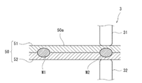
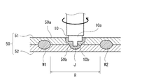
- FIG. 1 is a configuration diagram schematically showing a friction stir spot welding device 2 of a spot welding device 1 according to an embodiment.
- the workpiece 50 is a pair of plate members 51 and 52 that are overlapped with each other, and the friction stir spot welding device 2 spot-joins the overlapping portions 50 a of the pair of plate members 51 and 52.
- the friction stir spot joining device 2 includes a base body 11, a movable body 12 attached to the base body 11, and a tool holder 13 projecting from the movable body 12 toward the workpiece 50.
- the movable body 12 is attached to the base 11 so as to be slidable along the axis of the tool holder 13.
- the tool holder 13 is configured to be rotatable about its axis, and the tool 10 is detachably attached to the tip of the tool holder 13.
- a curved frame 14 curved in a substantially L shape is fixed to the base body 11.
- the curved frame 14 extends to a position where the distal end thereof faces the tool 10, and a support base 15 that supports the workpiece 50 is provided at the distal end of the curved frame 14.
- the base 11 is provided with a linear motion driver 16 that slides and displaces the movable body 12 in the axial direction of the tool holder 13.
- the linear motion driver 16 slides the movable body 12 to move the tool 10 forward and backward relative to the workpiece 50.
- the movable body 12 is provided with a rotation driver 17 that rotates the tool holder 13 about its axis.
- the rotation driver 17 rotates the tool 10 by rotating the tool holder 13.
- An articulated robot 18 is attached to the base 11.
- the articulated robot 18 displaces the tool 10 to a desired position with respect to the workpiece 50 by displacing the base body 11. That is, the linear motion driver 16 and the articulated robot 18 serve as a displacement driver 19 that relatively displaces the workpiece 50 and the tool 10 from each other.
- the friction stir spot joining device 2 includes a controller 20 that controls the linear motion driver 16, the rotation driver 17, and the articulated robot 18.
- the controller 20 may have a function integrated in one control unit, or may have a configuration in which functions are distributed to a plurality of control units.
- the controller 20 includes a processor, a volatile memory, a nonvolatile memory, an I / O interface, and the like.
- the controller 20 responds to a command input from an input device (not shown) (for example, a computer or teaching pendant) via the I / O interface, and the processor executes a volatile memory based on an operation program stored in the nonvolatile memory. And communicates with the rotation driver 17 and the displacement driver 19 via the I / O interface.
- the friction stir spot joining apparatus 2 controls the rotation driver 17 and the displacement driver 19 to be controlled by the controller 20 so that the tool 10 is pushed into the overlapping portion 50a of the pair of plate members 51 and 52 while being rotated. A portion softened by frictional heat in the portion 50a is stirred and plastically flowed, and friction stir spot welding is performed.
- FIG. 2 is a cross-sectional view for explaining the resistance spot welding process.
- the point joining device 1 of this embodiment further includes a resistance spot welding device 3.
- the resistance spot welding apparatus 3 includes a pair of welding electrodes 31, 32, an actuator (not shown) that displaces the welding electrodes 31, 32, and a controller (not shown) that controls the actuator.
- the resistance spot welding apparatus 3 energizes the overlapped portion 50a of the pair of plate members 51 and 52 between the pair of welding electrodes 31 and 32 and conducts resistance welding, so that a plurality of the overlapped portions 50a are spaced at a predetermined interval.
- Resistance spot welds W1 and W2 are formed, and a pair of plate members 51 and 52 are point-joined to each other.
- FIG. 3 is a cross-sectional view illustrating the friction stir spot joining step.
- the friction stir spot joining device 2 includes at least one friction stir spot joining in a region R between the plurality of resistance spot welds W1 and W2 in the overlapping portion 50a of the pair of plate members 51 and 52.
- the part J is formed, and the pair of plate members 51 and 52 are spot-bonded to each other.
- the tool 10 includes a tool main body 10a and a pin 10b having a smaller diameter than the tool main body 10a and protruding from the center of the tool main body 10a toward the work 50.
- the controller 20 controls the linear actuator 16 in a state where the rotational speed of the tool 10 reaches the target rotational speed by controlling the rotational driver 17 and the pin portion.
- the tool 10 is displaced until 10b presses the overlapping portion 50a of the workpiece 50.
- the pin portion 10b of the tool 10 softens the overlapping portion 50a of the work 50 by frictional heat, and stirs the softened portion 50b to cause plastic flow.
- the controller 20 displaces the tool 10 in the direction in which the tool 10 is pulled out from the workpiece 50 by the linear motion driver 16 after a predetermined joining processing time (the immersion time of the pin portion 10b) has elapsed.
- the joint structure 100 is formed by joining the overlapping portions 50a of the pair of plate members 51 and 52 by both resistance spot welding and friction stir spot joining.
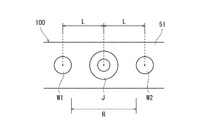
- FIG. 4 is a plan view of the main part of the joint structure 100.
- the joint structure 100 is a point structure in which a pair of plate members 51 and 52 are overlapped with each other, and is used for a structure such as an automobile, an aircraft, and a railway vehicle.
- the joint structure 100 is formed in a region R between a pair of resistance spot welds W1, W2 formed on the overlapping portion 50a of the pair of plate members 51, 52 and a pair of resistance spot welds W1, W2.
- two friction stir spot joints J J.
- the joint pitch L between the friction stir spot joint J and the resistance spot welds W1, W2, that is, the distance L between the center of the friction stir spot joint J and the center of each of the resistance spot welds W1, W2. Is preferably set within a predetermined range.
- a preferable range of the joining pitch L will be described.
- FIG. 5 is a graph showing the relationship between the joining pitch and the tensile shear strength in the tensile shear test.
- a DP980 steel plate tensile strength of 980 MPa
- the black plot in FIG. 5 is a result of a tensile shear test of a joint structure having one resistance spot weld and one friction stir spot joint (hereinafter referred to as “resistance spot welding + friction stir spot joint”).
- the solid line is the approximate line.
- the white plot in FIG. 5 shows the result of a tensile shear test of a joint structure having two resistance spot welds (hereinafter referred to as “resistance spot welding + resistance spot welding”), and the broken line is an approximate line thereof.
- the joining pitch is 6 mm or more and 20 mm or less, “resistance spot welding + friction stir spot welding” has higher tensile shear strength than “resistance spot welding + resistance spot welding”. If the joint pitch is too short, the joint pitch between the resistance spot weld and the friction stir spot joint will be shorter than the sum of the resistance spot weld radius and the friction stir spot joint radius. The welded portion and the friction stir spot joint portion overlap each other to reduce the total joint area, thereby reducing the joint strength improvement effect. Therefore, the joining pitch is preferably 6 mm or more so that the resistance spot weld and the friction stir spot joining part do not overlap each other.
- the lower limit value of the joint pitch at which the tensile shear strength is higher in “resistance spot welding + friction stir spot welding” than in “resistance spot welding + resistance spot welding” is the resistance spot weld and the friction stir spot joint.
- the plot with a joining pitch of 0 mm in FIG. 5 shows the tensile shear strength at a single point. In this case, the resistance spot welded portion has a higher tensile shear strength per point than the friction stir spot joined portion. It means it was expensive.
- the reactive current generated by shunting during resistance spot welding decreases, so the resistance shear welding + resistance spot welding is more tensile shear strength than resistance spot welding + friction stir spot welding Becomes higher.
- the reactive current increases in “resistance spot welding + resistance spot welding”, so “resistance spot welding + friction stir spot joining” is more “resistance spot welding + resistance spot welding”.
- the tensile shear strength is higher than that of “welding”.
- the joining pitch between the friction stir spot joint and the resistance spot weld is preferably set to a value of 20 mm or less.
- the upper limit of the joint pitch at which the tensile shear strength is higher in “resistance spot welding + friction stir spot welding” than in “resistance spot welding + resistance spot welding” is that it depends on the material and thickness of the plate. This will be described below.
- FIG. 6 is a graph showing the relationship between the plate thickness and the minimum joint pitch when resistance spot welding of low carbon steel (S10C or the like) is performed.
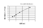
- FIG. 7 is a graph showing the relationship between the plate thickness and the minimum joining pitch when resistance spot welding of medium carbon steel (S20C, S35C, S45C, etc.) or low alloy steel (SNCM439, SCM435, etc.).
- the low carbon steel is a steel having a carbon content (mass percent concentration) of less than 0.20%
- the medium carbon steel is a steel having a carbon content of 0.20% to 0.6%.
- Steel is steel having a content (mass percent concentration) of alloy elements other than iron and carbon of 5% or less.
- the minimum joining pitch means the lower limit value of the joining pitch required when a pair of plate members are joined only by resistance spot welding.
- the minimum joining pitch required when a pair of plate members are joined only by resistance spot welding increases as the plate thickness of the plate increases. Further, the minimum joining pitch required when a pair of plate materials are joined only by resistance spot welding is shorter when the plate material is low carbon steel than when the plate material is medium carbon steel or low alloy steel. . That is, as the plate thickness increases, reactive current is likely to occur, and low carbon steel is less likely to generate reactive current than medium carbon steel or low alloy steel.
- “resistance spot welding + friction stir spot welding” has higher tensile shear strength than “resistance spot welding + resistance spot welding”.
- the controller 20 sets the joint pitch L between the friction stir spot joint J and the resistance spot welds W1 and W2 to Y ⁇ ⁇ 1. set so as to satisfy the 4X 2 + 18.6X + 0.6, when plate member 51 and 52 of medium carbon steel or low alloy steel, the junction between the friction stir spot joining portion J and the resistance point welds W1, W2 The pitch L is set so as to satisfy Y ⁇ ⁇ 1.9X 2 + 25.5X + 2.1.
- the controller 20 sets the joining pitch L between the friction stir spot joint J and the resistance spot welds W1 and W2 between the radius of the resistance spot weld J and the radius of the friction stir spot joint W1 (W2).
- the controller 20 sets the joint pitch L between the friction stir spot joint J and the resistance spot welds W1 and W2 as the pair of the friction stir spot joint and the resistance spot weld on a pair of plates.
- the joint shear pitch is set to be higher than the tensile shear strength when a pair of resistance spot welds is formed on a pair of plate materials.
- the joining pitch L of the spot joining points can be shortened. That is, by reducing the reactive current by increasing the distance between the resistance spot welds W1 and W2, it is possible to prevent a decrease in the bonding strength and appearance quality and a variation in the bonding strength, and as a whole, the point bonding point.
- the joint pitch L By shortening the joint pitch L, the joint strength and the rigidity of the joint structure 100 can be increased.
- the controller 20 sets the joint pitch L between the friction stir spot joint J and the resistance spot welds W1 and W2 to “resistance spot weld + resistance stir spot” in the case of “resistance spot weld + friction stir spot joint”. Since the joint pitch is set such that the tensile shear strength is higher than that of the “spot welded portion”, it is possible to suitably achieve both prevention of joint strength reduction due to reactive current during resistance spot welding and improvement of joint strength by shortening the joint pitch. Further, the controller 20 sets the joining pitch L between the friction stir spot joint J and the resistance spot welds W1 and W2 between the radius of the resistance spot weld W1 (W2) and the radius of the friction stir spot joint J. Since the value is set to be longer than the total, it is possible to prevent the friction stir spot joint J and the resistance spot welds W1 and W2 from overlapping each other, thereby reducing the total joint area and effectively increasing the joint strength.
- the present invention is not limited to the above-described embodiment, and the configuration can be changed, added, or deleted.
- the joint pitch between the friction stir spot joint J and the resistance spot weld W1 may be different from the joint pitch between the friction stir spot joint J and the resistance spot weld W2.
- the friction stir spot joint J is provided on a straight line connecting the pair of resistance spot welds W1 and W2, but the overlapping portion of the plate material has a curved portion curved in plan view. May be provided between a pair of resistance spot welds on a curve line extending in the extending direction of the curve.
- the displacement driver may move the workpiece with respect to the tool.
- the number of plate members that are overlapped with each other and are point-joined may be three or more.
Landscapes
- Engineering & Computer Science (AREA)
- Mechanical Engineering (AREA)
- Pressure Welding/Diffusion-Bonding (AREA)
- Resistance Welding (AREA)
Abstract
L'invention concerne un dispositif de soudage par points, qui empile une pluralité de matériaux en plaque et effectue un soudage par points, et qui est pourvu : d'un dispositif d'entraînement en déplacement pour un déplacement relatif de parties de chevauchement de la pluralité de matériaux en plaque et d'un outil ; d'un dispositif d'entraînement en rotation pour faire tourner l'outil ; d'un dispositif de commande pour commander le dispositif d'entraînement en déplacement et le dispositif d'entraînement en rotation de telle sorte que l'outil est pressé dans les parties de chevauchement dans un état de rotation de façon à effectuer un soudage par friction-malaxage. Le dispositif de commande commande le dispositif d'entraînement en déplacement de telle sorte qu'au moins une partie de soudage par points par friction-malaxage est formée dans une région entre une pluralité de parties de soudage par points à résistance où un soudage est effectué avec un soudage par points à résistance dans les parties de chevauchement.
Priority Applications (4)
| Application Number | Priority Date | Filing Date | Title |
|---|---|---|---|
| EP17789680.0A EP3450080B1 (fr) | 2016-04-28 | 2017-04-27 | Dispositif de soudage par points et procédé de soudage par points |
| KR1020187033701A KR102207831B1 (ko) | 2016-04-28 | 2017-04-27 | 점 접합 장치, 점 접합 방법 및 이음 구조 |
| CN201780025929.1A CN109070264B (zh) | 2016-04-28 | 2017-04-27 | 点接合装置、点接合方法及接头结构 |
| US16/097,496 US11040413B2 (en) | 2016-04-28 | 2017-04-27 | Spot welding apparatus, spot welding method, and joint structure |
Applications Claiming Priority (2)
| Application Number | Priority Date | Filing Date | Title |
|---|---|---|---|
| JP2016090611A JP6393707B2 (ja) | 2016-04-28 | 2016-04-28 | 点接合装置、点接合方法及び継手構造 |
| JP2016-090611 | 2016-04-28 |
Publications (1)
| Publication Number | Publication Date |
|---|---|
| WO2017188399A1 true WO2017188399A1 (fr) | 2017-11-02 |
Family
ID=60160780
Family Applications (1)
| Application Number | Title | Priority Date | Filing Date |
|---|---|---|---|
| PCT/JP2017/016816 Ceased WO2017188399A1 (fr) | 2016-04-28 | 2017-04-27 | Dispositif de soudage par points, procédé de soudage par points et structure de raccord |
Country Status (6)
| Country | Link |
|---|---|
| US (1) | US11040413B2 (fr) |
| EP (1) | EP3450080B1 (fr) |
| JP (1) | JP6393707B2 (fr) |
| KR (1) | KR102207831B1 (fr) |
| CN (1) | CN109070264B (fr) |
| WO (1) | WO2017188399A1 (fr) |
Cited By (1)
| Publication number | Priority date | Publication date | Assignee | Title |
|---|---|---|---|---|
| CN116981534A (zh) * | 2021-03-30 | 2023-10-31 | 川崎重工业株式会社 | 接合结构体及接合方法 |
Families Citing this family (11)
| Publication number | Priority date | Publication date | Assignee | Title |
|---|---|---|---|---|
| EP3680051B1 (fr) * | 2017-09-04 | 2023-08-16 | Kawasaki Jukogyo Kabushiki Kaisha | Procédé de fonctionnement d'un dispositif de soudage par friction-malaxage à double action, et dispositif de soudage par friction-malaxage à double action |
| CN112770863B (zh) * | 2018-10-11 | 2022-07-29 | 川崎重工业株式会社 | 摩擦搅拌接合装置、其运转方法以及接头构造 |
| US10442029B1 (en) * | 2019-04-10 | 2019-10-15 | King Saud University | Method of friction stir spot welding |
| JP7223651B2 (ja) * | 2019-07-01 | 2023-02-16 | 川崎重工業株式会社 | 接合システム及びその運転方法 |
| KR102230872B1 (ko) * | 2019-12-19 | 2021-03-24 | 주식회사 포스코 | 전착 드럼용 티타늄 링의 제조방법 및 이에 의해 제조된 전착 드럼용 티타늄 링 |
| CN111468849B (zh) * | 2020-04-15 | 2021-07-13 | 广东省资源综合利用研究所 | 一种稀土磁盘焊接工艺 |
| US11958126B2 (en) * | 2020-10-06 | 2024-04-16 | GE Precision Healthcare LLC | Containers for retaining anesthetic agent and manufacturing methods thereof |
| WO2022145382A1 (fr) * | 2020-12-28 | 2022-07-07 | 川崎重工業株式会社 | Procédé d'assemblage, corps assemblé et dispositif d'assemblage |
| WO2022239795A1 (fr) * | 2021-05-14 | 2022-11-17 | 川崎重工業株式会社 | Procédé d'assemblage et corps assemblé |
| JP7353329B2 (ja) * | 2021-07-16 | 2023-09-29 | 本田技研工業株式会社 | 摩擦攪拌接合及び抵抗溶接のための接合装置及び接合方法 |
| KR102877383B1 (ko) * | 2021-08-31 | 2025-10-27 | 제이에프이 스틸 가부시키가이샤 | 마찰 교반점 접합 조인트 및 그의 제조 방법, 그리고, 마찰 교반점 접합 방법 |
Citations (4)
| Publication number | Priority date | Publication date | Assignee | Title |
|---|---|---|---|---|
| JP2006167747A (ja) * | 2004-12-15 | 2006-06-29 | Honda Motor Co Ltd | 溶接装置及び加工方法 |
| JP2009202828A (ja) * | 2008-02-29 | 2009-09-10 | Mazda Motor Corp | 車体の製造方法および製造ライン |
| JP2015033706A (ja) * | 2013-08-08 | 2015-02-19 | 株式会社神戸製鋼所 | スポット・レーザ複合溶接継手 |
| DE102016206759A1 (de) * | 2015-07-21 | 2017-01-26 | Ford Global Technologies, Llc | Verfahren zum Verbinden von wenigstens zwei an einander liegenden Metall-Werkstücken |
Family Cites Families (14)
| Publication number | Priority date | Publication date | Assignee | Title |
|---|---|---|---|---|
| JPS5285278A (en) | 1976-01-09 | 1977-07-15 | Nippon Oil Co Ltd | Production of polyolefin |
| JP2580029B2 (ja) * | 1989-03-20 | 1997-02-12 | ファナック株式会社 | 溶接ロボットにおけるピッチ可変型スポット溶接ガン装置 |
| EP1346792A1 (fr) * | 2002-03-21 | 2003-09-24 | H.A. Schlatter Ag | Appareil de soudage |
| JP2004276724A (ja) * | 2003-03-14 | 2004-10-07 | Tokyu Car Corp | 鉄道車両の車体およびその製造方法 |
| JP3860153B2 (ja) * | 2003-09-12 | 2006-12-20 | 川崎重工業株式会社 | 継ぎ手構造 |
| DE102005001341B3 (de) * | 2005-01-11 | 2006-10-05 | Kuka Schweissanlagen Gmbh | Verfahren und Vorrichtung zum elektrischen Punktschweißen |
| JP5044162B2 (ja) * | 2006-07-31 | 2012-10-10 | トヨタ自動車株式会社 | 異種金属継手構造及び異種金属接合方法 |
| US20080149687A1 (en) * | 2006-12-22 | 2008-06-26 | Garnett Mark D | Weld Inspection Optimizer |
| JP5521421B2 (ja) * | 2009-07-21 | 2014-06-11 | スズキ株式会社 | 複式溶接ガン構造体 |
| JP5391046B2 (ja) * | 2009-12-07 | 2014-01-15 | 川崎重工業株式会社 | 摩擦攪拌接合装置及びその接合方法 |
| US8052029B1 (en) * | 2010-09-01 | 2011-11-08 | GM Global Technology Operations LLC | Method of calibrating a friction stir spot welding system |
| JP5605405B2 (ja) | 2012-08-07 | 2014-10-15 | 新日鐵住金株式会社 | 抵抗溶接接合体 |
| KR101382319B1 (ko) * | 2012-12-17 | 2014-04-08 | 현대자동차 주식회사 | 트윈 스폿 용접장치 |
| CN103170752A (zh) * | 2013-04-09 | 2013-06-26 | 上海电机学院 | 搅拌摩擦电阻点焊装置及其方法 |
-
2016
- 2016-04-28 JP JP2016090611A patent/JP6393707B2/ja active Active
-
2017
- 2017-04-27 WO PCT/JP2017/016816 patent/WO2017188399A1/fr not_active Ceased
- 2017-04-27 KR KR1020187033701A patent/KR102207831B1/ko not_active Expired - Fee Related
- 2017-04-27 US US16/097,496 patent/US11040413B2/en not_active Expired - Fee Related
- 2017-04-27 EP EP17789680.0A patent/EP3450080B1/fr active Active
- 2017-04-27 CN CN201780025929.1A patent/CN109070264B/zh not_active Expired - Fee Related
Patent Citations (4)
| Publication number | Priority date | Publication date | Assignee | Title |
|---|---|---|---|---|
| JP2006167747A (ja) * | 2004-12-15 | 2006-06-29 | Honda Motor Co Ltd | 溶接装置及び加工方法 |
| JP2009202828A (ja) * | 2008-02-29 | 2009-09-10 | Mazda Motor Corp | 車体の製造方法および製造ライン |
| JP2015033706A (ja) * | 2013-08-08 | 2015-02-19 | 株式会社神戸製鋼所 | スポット・レーザ複合溶接継手 |
| DE102016206759A1 (de) * | 2015-07-21 | 2017-01-26 | Ford Global Technologies, Llc | Verfahren zum Verbinden von wenigstens zwei an einander liegenden Metall-Werkstücken |
Cited By (1)
| Publication number | Priority date | Publication date | Assignee | Title |
|---|---|---|---|---|
| CN116981534A (zh) * | 2021-03-30 | 2023-10-31 | 川崎重工业株式会社 | 接合结构体及接合方法 |
Also Published As
| Publication number | Publication date |
|---|---|
| CN109070264A (zh) | 2018-12-21 |
| EP3450080A4 (fr) | 2019-12-04 |
| KR20180132154A (ko) | 2018-12-11 |
| KR102207831B1 (ko) | 2021-01-26 |
| CN109070264B (zh) | 2021-08-20 |
| US20190143442A1 (en) | 2019-05-16 |
| EP3450080A1 (fr) | 2019-03-06 |
| JP2017196649A (ja) | 2017-11-02 |
| JP6393707B2 (ja) | 2018-09-19 |
| US11040413B2 (en) | 2021-06-22 |
| EP3450080B1 (fr) | 2023-10-04 |
Similar Documents
| Publication | Publication Date | Title |
|---|---|---|
| JP6393707B2 (ja) | 点接合装置、点接合方法及び継手構造 | |
| JP7247996B2 (ja) | 両面摩擦撹拌接合用回転ツール及び両面摩擦撹拌接合方法 | |
| JP7684900B2 (ja) | 摩擦攪拌点接合装置、摩擦攪拌点接合された被接合物、及びショルダ部材 | |
| CN101687282A (zh) | 焊接装置及焊接方法 | |
| JP2003320465A (ja) | テーパー摩擦撹拌溶接工具 | |
| KR20130056302A (ko) | 마찰교반용접 동안에 로드를 최소화하기 위한 고회전 속력을 사용한 시스템 | |
| JP5261984B2 (ja) | 抵抗スポット溶接方法 | |
| CN113993656B (zh) | 接合系统及其运行方法 | |
| JP7278300B2 (ja) | 摩擦攪拌接合装置、その運転方法、及び継手構造 | |
| JP2019136748A (ja) | 抵抗スポット溶接方法 | |
| JP2009226446A (ja) | 異種板材のスポット溶接方法 | |
| JP4865608B2 (ja) | 溶接部の補修方法及び補修装置 | |
| CN115776922A (zh) | 搅拌摩擦点焊装置及搅拌摩擦点焊方法 | |
| JP5609966B2 (ja) | 抵抗スポット溶接方法 | |
| KR102747977B1 (ko) | 마찰교반 점접합 장치 및 그 운전 방법 | |
| JP5872319B2 (ja) | 片側スポット溶接装置及び片側スポット溶接方法 | |
| CN110325314A (zh) | 接合方法 | |
| JP2018187672A (ja) | 接合方法 | |
| JP2018083217A (ja) | 摩擦攪拌接合方法 | |
| JP2018187671A (ja) | 接合方法 | |
| JP6769244B2 (ja) | 接合方法 | |
| JP6740963B2 (ja) | 接合方法 | |
| CN112351857A (zh) | 摩擦搅拌点接合装置的衬垫部件、摩擦搅拌点接合装置、摩擦搅拌点接合方法以及接头构造 | |
| JP2020104121A (ja) | 摩擦攪拌接合ツールユニット、制御装置及び摩擦攪拌接合方法 | |
| JP2018126766A (ja) | 接合方法 |
Legal Events
| Date | Code | Title | Description |
|---|---|---|---|
| NENP | Non-entry into the national phase |
Ref country code: DE |
|
| ENP | Entry into the national phase |
Ref document number: 20187033701 Country of ref document: KR Kind code of ref document: A |
|
| 121 | Ep: the epo has been informed by wipo that ep was designated in this application |
Ref document number: 17789680 Country of ref document: EP Kind code of ref document: A1 |
|
| ENP | Entry into the national phase |
Ref document number: 2017789680 Country of ref document: EP Effective date: 20181128 |