WO2017191742A1 - Dispositif d'entrée - Google Patents
Dispositif d'entrée Download PDFInfo
- Publication number
- WO2017191742A1 WO2017191742A1 PCT/JP2017/015047 JP2017015047W WO2017191742A1 WO 2017191742 A1 WO2017191742 A1 WO 2017191742A1 JP 2017015047 W JP2017015047 W JP 2017015047W WO 2017191742 A1 WO2017191742 A1 WO 2017191742A1
- Authority
- WO
- WIPO (PCT)
- Prior art keywords
- unit
- input device
- power generation
- generation unit
- piezoelectric element
- Prior art date
- Legal status (The legal status is an assumption and is not a legal conclusion. Google has not performed a legal analysis and makes no representation as to the accuracy of the status listed.)
- Ceased
Links
Images


Classifications
-
- H—ELECTRICITY
- H01—ELECTRIC ELEMENTS
- H01H—ELECTRIC SWITCHES; RELAYS; SELECTORS; EMERGENCY PROTECTIVE DEVICES
- H01H13/00—Switches having rectilinearly-movable operating part or parts adapted for pushing or pulling in one direction only, e.g. push-button switch
- H01H13/02—Details
- H01H13/12—Movable parts; Contacts mounted thereon
- H01H13/14—Operating parts, e.g. push-button
-
- H—ELECTRICITY
- H01—ELECTRIC ELEMENTS
- H01H—ELECTRIC SWITCHES; RELAYS; SELECTORS; EMERGENCY PROTECTIVE DEVICES
- H01H13/00—Switches having rectilinearly-movable operating part or parts adapted for pushing or pulling in one direction only, e.g. push-button switch
- H01H13/70—Switches having rectilinearly-movable operating part or parts adapted for pushing or pulling in one direction only, e.g. push-button switch having a plurality of operating members associated with different sets of contacts, e.g. keyboard
Definitions
- This disclosure relates to an input device used for an electronic device or the like.
- a conventional input device is disclosed in Patent Document 1, for example.
- the conventional input device disclosed in Patent Document 1 includes a housing, a plurality of switch keys, a plurality of switches, a power generation unit, and a link mechanism that connects the plurality of switch keys and the power generation unit.
- the link mechanism has a first link lever and a second link lever.
- the switch key, the switch, the power generation unit, and the link mechanism are housed in the housing. Part of each of the plurality of switch keys is exposed from the housing.
- Each of the plurality of switch keys has a pin that pushes down the switch by a push-down operation of the switch key.
- the link mechanism transmits the push-down operation of the switch key to the power generation unit.
- the power generation unit generates power when the switch key pressing operation is transmitted by the link mechanism. That is, the conventional input device generates power when the switch key is pressed by the operator.
- the input device of the present disclosure includes a drive body having a sensor unit and a power generation unit having a piezoelectric element.
- the driving body slides in the first direction by the operation of the operator.
- the piezoelectric element of the power generation unit vibrates as the driving body slides in the first direction.
- the power generation unit generates power by vibration of the piezoelectric element.
- the sensor unit detects the operation of the operator using the electric power generated by the power generation unit and outputs a detection signal.
- FIG. 1 is a perspective view of an input device according to an embodiment of the present disclosure.
- 2 is a cross-sectional view taken along line 2-2 of the input device shown in FIG.
- FIG. 3 is a cross-sectional view when the input device shown in FIG. 1 is pressed.
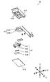
- FIG. 4 is an exploded perspective view of the input device shown in FIG.
- FIG. 5 is a diagram illustrating the configuration of the keypad and the driver in the input device shown in FIG.
- FIG. 6 is a circuit block diagram of the input device shown in FIG.
- FIG. 7 is a front view of an input device according to a modified example of the present disclosure.
- FIG. 8 is a sectional view taken along line 8-8 of the input device shown in FIG.
- FIG. 9 is a cross-sectional view taken along line 9-9 of the input device shown in FIG.
- FIG. 10 is a front view of the power generation unit in the input device shown in FIG. 11 is a cross-sectional view of the power generation unit shown in FIG. 10 taken along line 11-11.
- 12 is a cross-sectional view taken along line 12-12 of the power generation unit shown in FIG.
- FIG. 13 is an exploded perspective view of the power generation unit shown in FIG.
- the conventional input device has a configuration in which the link mechanism has the first link lever and the second link lever, the configuration becomes complicated. Therefore, there is a problem that the input device is large.
- the driving body having the sensor unit also serves as a part of the mechanism for vibrating the piezoelectric element, the mechanism for generating power is simple. Therefore, a small input device can be realized.
- FIG. 1 is a perspective view of the input device 1001.
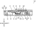
- FIG. 2 is a cross-sectional view of the input device 1001.
- FIG. 3 is a cross-sectional view when the input device 1001 is pressed.
- FIG. 4 is an exploded perspective view of the input device 1001. 2 and 3 are cross-sectional views taken along line 2-2 shown in FIG.
- the input device 1001 is a wireless remote controller, for example.
- the input device 1001 may be, for example, a wired remote controller.
- the input device 1001 not only transmits predetermined data assigned to a button operated by the operator, but also is connected to a device that measures the usage amount of gas or electricity, for example, and is operated by an operation by the operator.
- the generated power can be used as a device for transmitting data including the usage amount.
- the input device 1001 includes a keypad 20, a drive body 21, a power generation unit 22, a control unit 23, an activation unit 24, and a transmission unit 28.
- a plurality of sensor portions 21 ⁇ / b> A are formed on the drive body 21.
- the power generation unit 22 includes a piezoelectric element 22A.
- An activation unit 24 is disposed on the lower surface of the drive body 21.
- the starter 24 joined to the driving body 21 moves in the first direction.
- the starting unit 24 releases the load after bending the first end (downward) of the piezoelectric element 22A with a load in the first direction. Thereby, the piezoelectric element 22A of the power generation unit 22 vibrates to generate electric power.
- the control unit 23 is driven by the electric power generated by the power generation unit 22. Furthermore, 21 A of sensor parts detect the input operation (press operation to 20 A of operation buttons) by an operator using the electric power which the electric power generation part 22 generated, and output a detection signal. The detection signal is input to the control unit 23. The control unit 23 outputs a signal corresponding to the input detection signal to the transmission unit 28. And the transmission part 28 transmits the output signal according to a detection signal to the outward.
- the input device 1001 is configured such that the drive body 21 having the sensor unit 21A slides in the first direction by an input operation by the operator. That is, the drive body 21 that detects the input operation of the operator also serves as part or all of the mechanism for generating the power generation unit 22. Therefore, the input device 1001 can be downsized because the mechanism for power generation can be simplified.
- the input device 1001 includes a housing 26, a keypad 20, a driving body 21, a power generation unit 22, a control unit 23, an activation unit 24, a transmission unit 28, a slide mechanism unit 40, and a screw 30.
- the slide mechanism unit 40 may be composed of the pantograph mechanism 25 and the spring 29.
- the keypad 20, the drive body 21, the power generation unit 22, the control unit 23, the activation unit 24, the transmission unit 28, and the slide mechanism unit 40 are accommodated in the housing 26. A part of the keypad 20 is exposed from the housing 26.
- the housing 26 includes an upper housing 26A and a lower housing 26B as shown in FIG.
- the upper housing 26A and the lower housing 26B are joined by screws 30.
- the upper housing 26A and the lower housing 26B may be joined not only by the screws 30 but also by welding or a snap structure.
- the upper housing 26A has a plurality of through holes 26C.
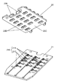
- the keypad 20 is made of rubber, for example, and is an elastic body. As shown in FIG. 4, the keypad 20 is formed with a plurality of operation buttons 20A protruding upward with respect to the plate-like base body 20C. Further, as shown in FIG. 5, a conductive portion 20B is formed on the lower surface of the keypad 20 at a position corresponding to the operation button 20A. The conductive portion 20B is formed of a conductive material such as a carbon-based material. The upper part of the operation button 20A protrudes outward from the through hole 26C of the upper housing 26A. The operator performs a predetermined input to the input device 1001 by pressing the operation button 20A.
- the operation button 20A is not limited to the configuration protruding from the upper surface of the upper casing 26A, and may be configured to be recessed from the upper surface of the upper casing 26A.
- Various displays (not shown) are formed on the upper surface of the operation button 20 ⁇ / b> A of the keypad 20. With this configuration, the operator can visually recognize the display and operate the operation button 20A.
- the drive body 21 is a flat plate-like member disposed below the keypad 20.
- the drive body 21 is held by a slide mechanism section 40 described later so that the drive body 21 can slide up and down within the housing 26. That is, the driving body 21 slides in the first direction (downward direction) and the second direction (upward direction).
- the drive body 21 has a plurality of sensor units 21A that detect pressing operations of the operation buttons 20A by the operator.
- the upper surface of the driver 21 is preferably flat. Therefore, the driving body 21 is preferably flat.
- the drive body 21 in this Embodiment is a plate-shaped wiring board, for example, is made from an epoxy resin. Below, the structure of the keypad 20 and the drive body 21 is demonstrated in detail.
- FIG. 5 is an exploded perspective view of the keypad 20 and the drive body 21.
- the conductive portion 20B is formed on the lower surface of the keypad 20 at a position corresponding to the operation button 20A.
- sensor portions 21A are formed at positions corresponding to the conductive portions 20B of the keypad 20, respectively.
- the sensor unit 21A and the conductive unit 20B face each other at a predetermined interval. That is, the sensor unit 21A and the conductive unit 20B are not in contact.
- the sensor unit 21A includes a first electrode 21B and a second electrode 21C.
- the first electrode 21B and the second electrode 21C are wiring patterns formed in a predetermined shape on the wiring board, and are made of a metal material such as copper.
- the surface of the wiring pattern preferably has metal plating. For example, gold or silver can be used as a material for metal plating.
- the operation button 20A moves downward, and the conductive portion 20B and the sensor portion 21A come into contact with each other. That is, the conductive portion 20B is in contact with the first electrode 21B and the second electrode 21C. Thereby, the first electrode 21B and the second electrode 21C are electrically connected to each other.
- the drive body 21 is held so as to be slidable up and down by a slide mechanism section 40 described later, the operation button 20A is further pushed from the state where the conductive section 20B is in contact with the first electrode 21B and the second electrode 21C. When pushed down, the driving body 21 slides downward together with the operated operation button 20A.
- the input device 1001 is configured such that when any one of the plurality of operation buttons 20A is pressed down, the driving body 21 slides downward. Note that only the operation button 20A that has been pressed down slides downward on the keypad 20.
- the power generation unit 22 is disposed below the driving body 21 as shown in FIG.
- the power generation unit 22 includes a piezoelectric element 22A fixed in a cantilever shape.
- the piezoelectric element 22A is an element in which a piezoelectric material is formed in a thin plate shape on a thin metal plate, and generates electricity by deformation such as vibration.
- the metal plate is preferably a metal material having spring properties such as stainless steel. For example, it is preferable that the piezoelectric material is formed on both surfaces of a metal plate because the power generation amount can be improved.
- the piezoelectric material may be formed only on one side of the metal plate.
- the power generation unit 22 is fixed to the lower housing with screws or the like.
- the adsorbent 22B is fixed to the tip of the piezoelectric element 22A configured in a cantilever shape, and adsorbs to an activation unit 24 described later.
- the adsorbent 22B is, for example, a magnet.
- the starting portion 24 is a member formed of a plate-shaped metal material in a predetermined shape, and is formed through a fixed portion 24A fixed to the lower surface of the driving body 21 and an L-shaped step from the fixed portion 24A. It has a suction part 24B. As illustrated in FIG. 4, the suction portion 24B is located below the fixed portion 24A. The adsorption portion 24B is cut out in a U shape.
- the starter 24 is fixed to the lower surface of the drive body 21 and slides downward together with the drive body 21.
- the starting part 24 is a ferromagnetic body such as iron, and the upper surface of the attracting part 24B is attracted to the attracting body 22B (magnet) attached to the tip of the piezoelectric element 22A.
- the slide mechanism unit 40 slides the drive body 21 in the vertical direction.
- the slide mechanism unit 40 is accommodated in a gap between the driving body 21 and the lower housing 26B.
- the slide mechanism unit 40 for example, the pantograph mechanism 25 can be used.
- the slide mechanism unit 40 is connected to the drive body 21.
- the slide mechanism unit 40 preferably includes a spring 29.
- the spring 29 pushes up the driving body 21 upward.
- the driving body 21 returns to the initial position by the elastic force of the spring 29.
- the operation button 20A is made of rubber having elasticity, it can be restored to a shape protruding upward by its own restoring force after being bent downward by a pressing operation. Therefore, the keypad 20 can return to a state where the conductive portion 20B and the sensor portion 21A (the first electrode 21B and the second electrode 21C) do not contact each other.
- the spring 29 is compressed.
- the first electrode 21 ⁇ / b> B and the second electrode 21 ⁇ / b> C shown in FIG. 5 are pressed against the conductive portion 20 ⁇ / b> B of the keypad 20 by the reaction force of the spring 29. Therefore, the contact between the conductive portion 20B and the sensor portion 21A (the first electrode 21B and the second electrode 21C) is stabilized.
- the input device 1001 simplifies the mechanism for generating power by vibrating the piezoelectric element 22A of the power generation unit 22. Below, the operation
- the operation button 20A moves downward.
- the conductive portion 20B of the operation button 20A and the sensor unit 21A come into contact with each other.
- the first electrode 21B and the second electrode 21C are electrically connected.
- the drive body 21 slides downward as shown in FIG.
- the starting part 24 is joined to the driving body 21, it slides downward together with the driving body 21.
- the piezoelectric element 22A Since the piezoelectric element 22A is attracted to the activation part 24 by magnetic force, the tip of the piezoelectric element 22A bends downward as the activation part 24 slides. Then, when the restoring force that the piezoelectric element 22A that is bent downward returns to the original state becomes larger than the attracting force by the magnetic force, the piezoelectric element 22A moves away from the starter 24 and starts to vibrate. That is, the starting unit 24 vibrates the piezoelectric element 22 ⁇ / b> A by releasing the load after bending the piezoelectric element 22 ⁇ / b> A of the power generation unit 22 with a load. The power generation unit 22 generates power when the piezoelectric element 22A vibrates. The power generated by the power generation unit 22 is alternating current.
- the input device 1001 can generate power by an operator's input operation.
- the generated power is supplied to the drive body 21 (wiring board) or the like, and is used as drive power for the control unit 23 or the like mounted on the drive body 21.
- the operator receives a restoring force generated by the bending of the piezoelectric element 22A until the starting unit 24 and the power generation unit 22 are separated. That is, the operator receives a force pushing up from the operation button 20A in the second direction (upward).
- the driving body 21 is released from the restoring force due to the bending of the power generation unit 22. Accordingly, the force that pushes the operation button 20A upward decreases. Thereby, the operator gets an operation feeling.
- the operator can acquire an operation feeling reliably.
- the control unit 23 and the transmission unit 28 are arranged on the lower surface of the driving body 21 as shown in FIG. Note that both the control unit 23 and the transmission unit 28 are driven using the power generated by the power generation unit 22.
- a detection signal output from the sensor unit 21A is input to the control unit 23.
- the control unit 23 outputs a signal corresponding to the input detection signal to the transmission unit 28.
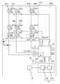
- FIG. 6 is a circuit block diagram of the input device 1001.
- Smn is the sensor unit 21A.
- Xmn is the first electrode 21B
- Ymn is the second electrode 21C.
- the control unit 23 has an output terminal 231 and an input terminal 232.
- the first electrode 21B (Xmn) of the sensor unit 21A (Smn) is electrically connected to the output terminal 231 of the control unit 23.
- the second electrode 21 ⁇ / b> C (Ymn) of the sensor unit 21 ⁇ / b> A (Smn) is electrically connected to the input terminal 232.
- the control unit 23 is mounted on the lower surface of the driving body 21 (wiring board) as shown in FIG.
- the control unit 23 is not limited to the configuration mounted on the lower surface of the drive body 21, and may be mounted on the upper surface of the drive body 21. Or the structure by which the control part 23 was mounted in the wiring board different from the drive body 21 may be sufficient.
- the control unit 23 sequentially outputs a predetermined signal from the output terminal 231 to the first electrode 21B (Xmn).
- the sensor unit 21A (Smn) is output from the output terminal 231.
- the predetermined signal is output as a detection signal. That is, a predetermined signal output from the output terminal 231 is input to the input terminal 232 as a detection signal via the sensor unit 21A (Smn). With this configuration, the control unit 23 can determine which operation button 20A the operator has operated.
- control part 23 has the output terminal 235 connected to the transmission part 28, as shown in FIG.
- An output signal from the output terminal 235 is input to the transmission unit 28.
- the transmission unit 28 is, for example, an infrared light emitting element.
- the output signal from the output terminal 235 is converted into an optical signal by the transmission unit 28 and transmitted to a receiver (not shown).
- the transmitting unit 28 is not limited to the infrared light emitting element, but may be a radio wave transmitting element.
- the output signal from the output terminal 235 is converted into a radio signal by the transmission unit 28.
- the transmission unit 28 transmits an output signal corresponding to the detection signal of the sensor unit 21A using the power generated by the power generation unit 22.
- the input device 1001 further includes a power storage unit 27.
- the power storage unit 27 is mounted on the drive body 21 (wiring board).
- the power storage unit 27 is electrically connected to the power generation unit 22 and stores power generated by the power generation unit 22.
- the power storage unit 27 is electrically connected to the power supply terminal 233 of the control unit 23 and supplies the power stored in the power storage unit 27 to the control unit 23.
- Power storage unit 27 includes a power storage element 27A and a rectifier circuit 27B.
- the power storage element 27A is, for example, a capacitor. Since the electric power generated by the piezoelectric element 22A is alternating current, the power storage unit 27 stores the power in the power storage element 27A after converting the power into direct current by the rectifier circuit 27B.
- the operation buttons 20A and the sensor units 21A are arranged in three rows in the X direction (right direction) and four rows in the Y direction (forward direction). In the rows at both ends in the X direction, five operation buttons 20A are arranged in the Y direction. That is, the number of operation buttons 20A in the rows at both ends in the X direction is one more than the number of operation buttons 20A in the center row in the X direction. Therefore, in the input device 1001, a total of 14 operation buttons 20A are arranged.
- the sensor units 21A are arranged in m columns in the X direction and n columns in the Y direction will be described. In this case, as shown in FIG.
- the driving body 21 has a sensor section 21A of S11 to Smn.
- the control unit 23 preferably includes a nonvolatile memory 234.
- the non-volatile memory 234 has a memory area that can specify which one of the sensor units S11 to Smn has been operated. Therefore, the non-volatile memory 234 preferably includes a plurality of memory areas.
- the sensor unit 21A (Smn) has an X electrode Xmn and a Y electrode Ymn.
- the sensor unit 21A (S11) includes an X electrode X11 and a Y electrode Y11.
- the X electrodes Xm1 to Xmn are all electrically connected.
- the Y electrodes Y1n to Ymn are all electrically connected.
- the control unit 23 preferably includes m output terminals 231 and n input terminals 232.
- the output terminal 231 includes output terminals OUT1 to OUTm.
- the input terminal 232 includes input terminals IN1 to INn.
- the X electrodes Xm1 to Xmn are each connected to the output terminal OUTm.
- the Y electrodes Y1n to Ymn are each connected to the input terminal INn.
- the X electrodes X11 to Xmn are, for example, the first electrodes 21B shown in FIG.
- the Y electrodes Y1n to Ymn are, for example, the second electrodes 21C shown in FIG.
- the conductive part 20B of the keypad 20 shown in FIG. 5 contacts the 1st electrode 21B and the 2nd electrode 21C by an operator's pressing operation.
- the sensor units Sm1 to Smn do not need to be arranged in a line in the Y direction. Further, the sensor units S1n to Smn do not need to be arranged in a line in the X direction. That is, the operation buttons 20A and the sensor unit 21A (Smn) need not be arranged in a grid pattern. That is, it is only necessary to detect which of the sensor units S11 to Smn is operated by the control unit 23, and the arrangement of the operation button 20A and the sensor unit 21A (Smn) is not limited.
- control unit 23 is not limited to the configuration having the m output terminals 231 and the n input terminals 232, and may include the n output terminals 231 and the m input terminals 232.
- the output terminal 231 includes output terminals OUT1 to OUTn.
- the input terminal 232 includes input terminals IN1 to INm.
- the X electrodes Xm1 to Xmn are connected to the input terminal INm.
- the Y electrodes Y1n to Ymn are connected to the output terminal OUTn.
- the operation of the input device 1001 will be described in more detail.
- the operator operates the operation button 20A corresponding to the sensor unit S22 illustrated in FIG. 6
- the conductive portion 20B of the keypad 20 comes into contact with the sensor portion S22. That is, the X electrode X22 and the Y electrode Y22 are electrically connected.
- the piezoelectric element 22A of the power generation unit 22 starts to vibrate.
- the electric power generated by the power generation unit 22 is supplied to the power storage unit 27.
- the power storage unit 27 converts the generated power into a constant voltage and supplies it to the control unit 23. Thereby, the control part 23 starts a drive.
- the control unit 23 outputs a predetermined output signal in the order of the output terminals OUT1 to OUTn.
- the output signal is, for example, a DC voltage signal having a predetermined voltage V1.
- the control unit 23 detects whether or not the sensor units S11 to Smn output detection signals in the order of the input terminals IN1 to INm. More specifically, the control unit 23 determines whether or not the output signal has returned to the control unit 23 in the order of the input terminals IN1 to INn while outputting the output signal from one output terminal OUTn. judge.
- the control unit 23 detects the predetermined voltage V1 (Hi) only at the input terminal IN2 among the input terminals IN1 to INm. Note that the voltages of the input terminals other than the input terminal IN2 are 0 V (Low). Therefore, the control part 23 can detect that the operator performed input operation with respect to sensor part S22.
- control unit 23 sequentially stores the detection results from the input terminals IN1 to INn in the nonvolatile memory 234. That is, as soon as the operation starts, the control unit 23 outputs an output signal from the output terminal 231 and performs an input determination operation of detecting the detection signal at the input terminal 232. Note that it is preferable that the control unit 23 does not perform other work during the input determination work. With this configuration, even when the operator quickly operates the operation button 20A, the control unit 23 can reliably detect the operation of the operator.
- the driving body 21 only needs to be able to detect an input operation by the operator, and may be, for example, a capacitive touch sensor or a touch panel.
- the touch panel may be either a capacitance type or a resistance film type. Moreover, what is necessary is just to be able to detect the input operation by the operator, and the input operation is not limited to the pressing operation.
- the adsorbent 22B of the power generation unit 22 also functions as a weight that assists the vibration of the piezoelectric element 22A.
- the metal plate of the piezoelectric element 22A is formed of stainless steel, for example. Since stainless steel is generally a non-magnetic material, it is preferable to use a magnet for the adsorbent 22B.
- the casing 26 is preferably formed of a resin material. Note that the entire housing 26 need not be made of resin. A metal material may be used for a part of the housing 26 as long as it does not hinder the adsorption by the adsorbent 22B. Moreover, it is preferable to form the starting part 24 with a magnetic material.
- the starting unit 24 is made of a nonmagnetic material
- an adsorbing body (not shown) may be attached to the starting unit 24.
- the adsorbent 22 ⁇ / b> B is disposed to face the adsorbent attached to the activation unit 24.
- the attracting member of the activation unit 24 is a magnetic material or a magnet.
- the lower housing 26B preferably includes a separation portion 26D.
- the activation unit 24 can slide to the lower side than the upper surface of the separation unit 26D.
- the power generation unit 22 comes into contact with the upper surface of the separation unit 26D and is restricted from moving downward. That is, the separation part 26D can suppress variation in the position where the starting part 24 and the piezoelectric element 22A are separated. Accordingly, the amplitude of the piezoelectric element 22A is stabilized. As a result, the power generation amount of the power generation unit 22 is stabilized. In addition, variations in the operation feel felt by the operator can be reduced.
- the separation unit 26D may be omitted.
- the restoring force of the piezoelectric element 22A increases as the amount of deflection of the power generation unit 22 increases. Then, when the reaction force of the piezoelectric element 22A becomes larger than the attracting force due to the magnetic force, the power generation unit 22 moves away from the activation unit 24 and starts to vibrate.
- the power generation unit 22 may have a configuration in which both ends of the piezoelectric element 22A are fixed.
- the adsorbent 22B is attached to the center of the piezoelectric element 22A.
- the center part of the electric power generation part 22 is adsorbed by the starting part 24, and the central part of an electric power generation part is bent.
- the starter 24 may generate power by flipping the tip of the piezoelectric element 22A to vibrate.
- the piezoelectric element 22A of the power generation unit 22 may be partially bent regardless of the flat plate shape.
- the entire power generation unit 22 may not be configured to be accommodated in the gap between the driving body 21 and the lower surface of the lower housing 26B. That is, the power generation unit 22 may be disposed so as to straddle the gap.
- the input device 1001 may reverse the arrangement of the power generation unit 22 and the activation unit 24. That is, the power generation unit 22 is joined to the drive body 21.
- the starting unit 24 is joined to the lower housing 26B.
- the power generation unit 22 slides as the drive body 21 moves.
- the piezoelectric element 22 ⁇ / b> A of the power generation unit 22 is vibrated by the activation unit 24. Even if it is the above structure, the drive body 21 becomes a structure which served as the mechanism for making the electric power generation part 22 generate electric power.
- the sensor unit 21A is configured to detect an input operation by electrically connecting the first electrode 21B and the second electrode 21C.
- the sensor unit 21A is not limited to this configuration, and a switch (not shown) or the like is used. Also good.
- the switch is mounted on the upper surface of the driver 21 (wiring board) by soldering or the like.
- the switch is switched by a predetermined operating force (pressing force). Further, the switch has an operation feeling when a pressing operation is performed. Therefore, it is preferable that the operation feeling by the piezoelectric element 22A of the power generation unit 22 is larger than the operation feeling of the switch.
- This configuration makes it difficult for the operator to feel the operation feeling of the switch alone. Therefore, the operator can be prevented from receiving the operation feeling of the switch alone and ending the operation of pressing down the operation button 20A. That is, it can be suppressed that the operator misunderstands that the input operation is completed before the power generation unit 22 generates power.
- the sensor unit 21A may be a membrane switch. Alternatively, the sensor unit 21A may be an electrostatic touch sensor. Further, the driving body 21 may include the keypad 20.
- the drive body 21 may be configured by a touch panel (not shown), for example. That is, the operator can input to the input device 1001 by operating the surface of the touch panel. Therefore, the operation area of the touch panel is exposed from the through hole 26C.
- the touch panel may be either a capacitance type or a resistance film type. That is, the input device 1001 can generate power with the same configuration as described above even when a touch panel is used as the driver 21.
- the drive unit 21 may directly vibrate the power generation unit 22. That is, the drive body 21 and the starting part 24 may be integrated. In this case, the drive body 21 also serves as the activation unit 24. With this configuration, the drive body 21 vibrates the power generation unit 22.
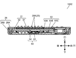
- FIG. 7 is a top view of the input device 1002.
- FIG. 8 is a cross-sectional view of the input device 1002.
- FIG. 8 shows a state in which the input device 1002 is cut along a sectional line 8-8 in FIG.
- An input device 1002 is a modification of the input device 1001 shown in FIG.
- the input device 1002 includes a slide mechanism unit 50. That is, the input device 1002 includes a slide mechanism unit 50 instead of the slide mechanism unit 40 shown in FIG.
- the input device 1001 shown in FIG. 1 may use the slide mechanism unit 50 shown in FIG. 8 instead of the slide mechanism unit 40 shown in FIG.
- the slide mechanism 50 has a pin 50B and a bearing 50C.
- the slide mechanism 50 preferably has a spring 50A.
- the pin 50B is inserted into the bearing 50C.
- the bearing 50C can slide and move in the vertical direction.
- the bearing 50 ⁇ / b> C is joined to the drive body 21. That is, the driving body 21 is held so as to be slidable in the vertical direction.
- the bearing 50C passes through the drive body 21.
- the pin 50B is joined to the housing 26.
- the first end of the pin 50B is joined to the upper casing 26A, and the second end is joined to the lower casing 26B.
- the thickness of the driving body 21 is thick. With this configuration, it is possible to prevent the bearing 50C from being attached to the drive body 21 in an inclined manner. Therefore, it can suppress that the drive body 21 inclines and slides. Therefore, the drive body 21 can move up and down smoothly.
- the driving body 21 includes a wiring board 31 and a reinforcing part 32.
- the slide mechanism unit 50 is not limited to the above-described configuration, and may be configured by a guide protrusion (not shown) and a guide groove (not shown), for example.
- a guide protrusion is provided on the outer peripheral side surface of the drive body 21.
- the guide protrusion protrudes in a direction facing the side surface of the lower housing 26B.
- a guide groove is provided inside the side surface of the lower housing 26B.
- the guide groove guides the guide protrusion in the vertical direction.
- the guide protrusion may be provided inside the side surface of the lower housing 26B.
- the guide groove is formed on the outer peripheral side surface of the drive body 21.
- FIG. 9 is a cross-sectional view of the input device 1002.
- FIG. 9 shows a state in which the input device 1002 is cut along a sectional line 9-9 in FIG.
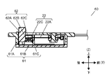
- FIG. 10 is a front view of the power generation unit 60.
- 11 and 12 are cross-sectional views of the power generation unit 60.
- FIG. 11 shows a state in which the power generation unit 60 is cut along a sectional line 11-11 in FIG.
- FIG. 12 shows a state where the power generation unit 60 is cut along a sectional line 12-12 in FIG.
- FIG. 13 is an exploded perspective view of the power generation unit 60.
- the input device 1002 has a power generation unit 60 instead of the power generation unit 22 shown in FIG.
- the power generation unit 60 includes an activation unit 62 and a power generation unit 22. That is, the input device 1002 includes an activation unit 62 instead of the activation unit 24.
- the power generation unit 60 further includes a sub case 61.
- the sub case 61 has an upper sub case 61A and a lower sub case 61B.
- the separation portion 26D is formed in the lower sub case 61B.
- the separation part 26D is not limited to the configuration formed in the lower sub case 61B, and may be provided in the lower housing 26B.
- the power generation unit 60 is modularized by housing the power generation unit 22 and the activation unit 62 in the sub case 61. Note that all or part of the subcase 61 may be integrated with the housing 26.
- the starting unit 62 is separated from the driving body 21.
- the starter 62 is in contact with the drive body 21 but is not joined.
- the starter 62 moves downward in contact with the drive body 21 as the drive body 21 moves downward. That is, the lower surface of the drive body 21 pushes the starting part 62 downward by a pressing operation by the operator. And the starting part 62 can move below with the drive body 21. Since the starting unit 62 is separated from the driving body 21, it is difficult to be affected by the displacement of the driving body 21 or the inclination of the direction in which the driving body 21 slides. Thereby, the drive body 21 can move to an up-down direction stably. Therefore, the power generation amount of the power generation unit 22 is also stabilized.
- the starter 62 is adsorbed to the power generation unit 22 by magnetic force, like the starter 24. Therefore, when the operator performs a pressing operation, the piezoelectric element 22A bends downward. Then, the piezoelectric element 22A is detached from the starting unit 62 and vibrates. When the pressing operation by the operator is released, the piezoelectric element 22A detached from the piezoelectric element 22A is attracted to the power generation unit 22 by the magnetic force and restored to the state of being adsorbed with the piezoelectric element 22A.
- the power generation unit 60 preferably includes a guide pin 61D and a guide hole 61C as shown in FIG.
- the guide pin 61D is inserted into the guide hole 61C.
- the guide pin 61D is not limited to the configuration penetrating the guide hole 61C, and may be halfway.
- the guide hole 61C is not limited to the through hole, and may be a bottomed hole.
- the configuration is not limited to the configuration in which the guide pin 61D is provided in the sub case 61 and the guide hole 61C is provided in the starting portion 62. That is, the guide pin 61D may be provided in the starting part 62, and the guide hole 61C may be provided in the sub case 61. Alternatively, the guide hole 61C and the guide pin 61D may be provided in the housing 26.
- the activation unit 62 preferably includes an activation button 62A and an adsorbent 62C.
- the adsorbent 62C is fixed to the start button 62A.
- a part of the start button 62 ⁇ / b> A penetrates the upper sub case 61 ⁇ / b> A and protrudes from the sub case 61.
- the activation button 62A can be formed of a resin material. With this configuration, the activation unit 62 can be lightened. Therefore, the starting unit 62 can quickly return to the initial position by the adsorption force between the adsorbent 22B and the adsorbent 62C.
- the activation button 62A is not limited to the configuration formed of a resin material, and all or part of the activation button 62A may be formed of a metal material. However, in this case, it is preferable to use a nonmagnetic material for the activation button 62A.
- the adsorbent 62C is formed of a magnet.
- the starting part 62 further includes a yoke 62B.
- the yoke 62B is provided opposite to the surface of the adsorbent 62C that faces the adsorbent 22B.
- the starting part 62 can be reduced, when the pressing operation by the operator is released, the starting part 62 can be attracted to the adsorbing body 22B by the magnetic force of the adsorbing body 62C. As a result, the starting unit 62 returns to the initial position.
- a buffer member (not shown) on either the lower surface of the adsorbent 22B or the upper surface of the adsorbent 62C.
- the input device 1002 is not limited to the configuration including both the slide mechanism unit 50 illustrated in FIG. 8 and the power generation unit 60 illustrated in FIG. 9, and may include only one of them. Further, the input device 1001 shown in FIG. 1 may include a power generation unit 60 instead of the power generation unit 22 shown in FIG.
- the driving body 21 preferably includes a wiring board 31.
- the control unit 23 and the power storage unit 27 are generally mounted on the wiring board 31. That is, electronic components such as the control unit 23 and the power storage unit 27 shown in FIG. 1 are mounted on the wiring board 31 by reflow soldering or the like.
- the drive body 21 preferably includes a reinforcing portion 32. By mounting the wiring board 31 on the upper surface of the reinforcing portion 32, unnecessary warping and deformation of the wiring board 31 can be suppressed.
- the wiring board 31 is fixed to the reinforcing portion 32 with screws, an adhesive, or the like. With this configuration, the wiring board 31 is fixed along the upper surface of the reinforcing portion 32. As a result, variation in stroke length of the operation button 20A can be reduced.
- the input devices 1001 and 1002 of the present disclosure include a driving body 21 including a sensor unit 21A and a power generation unit 22 including a piezoelectric element 22A.
- the sensor unit 21A detects the operation of the operator and outputs a detection signal.
- the driving body 21 slides in the first direction by the operation of the operator.
- the piezoelectric element 22 ⁇ / b> A of the power generation unit 22 vibrates when the drive body 21 slides in the first direction. Thereby, the power generation unit 22 generates power.
- 21 A of sensor parts output a detection signal using the electric power which the electric power generation part 22 generated.
- the input device 1001 includes an activation unit 24 that vibrates the piezoelectric element 22A of the power generation unit 22 based on the sliding movement of the driving body 21 in the first direction.
- the input device 1002 includes an activation unit 62 that vibrates the piezoelectric element 22A of the power generation unit 22 based on the sliding movement of the driving body 21 in the first direction.
- the activation units 24 and 62 vibrate the piezoelectric element 22A by releasing the load after bending the piezoelectric element 22A of the power generation unit 22 with a load.
- the starting unit 24 is joined to the drive body 21.
- the starting unit 24 slides in the first direction together with the driving body 21.
- the input device 1001 further includes a slide mechanism 40 that slides the drive body 21 that has been slid in the first direction in the second direction.
- the drive body 21 has a plate shape having a plane intersecting the second direction, and the sensor portion 21A is formed on the plane.
- the slide mechanism unit 40 is a pantograph mechanism that slides in the second direction while maintaining the inclination of the drive body 21.
- the slide mechanism unit 40 includes a spring 29 that pushes the drive body 21 in the second direction.
- the input device 1002 further includes a slide mechanism unit 50 that slides the drive body 21 that has been slid in the first direction in the second direction.
- the slide mechanism unit 50 includes a spring 50A that pushes the driving body 21 in the second direction.
- the sensor unit 21A includes a first electrode 21B and a second electrode 21C that is electrically independent of the first electrode 21B.
- the sensor unit 21A outputs a detection signal when the first electrode 21B and the second electrode 21C are electrically connected by an input operation of the operator.
- the driver 21 may be formed with a plurality of sensor units 21A.
- the driving body 21 slides in the first direction even when any one of the plurality of sensor units 21A is operated.
- the input devices 1001 and 1002 further include a control unit 23 that is driven using the power generated by the power generation unit 22.
- the control unit 23 includes an input terminal 232 to which detection signals output from the plurality of sensor units 21 ⁇ / b> A are input, and a nonvolatile memory 234. Based on the detection signal input to the input terminal 232, the control unit 23 stores information on which sensor unit 21 ⁇ / b> A of the plurality of sensor units 21 ⁇ / b> A has been operated in the nonvolatile memory 234.
- the input devices 1001 and 1002 further include a transmission unit 28 that is driven using the power generated by the power generation unit 22.
- the transmission part 28 transmits the output signal according to the detection signal of 21 A of sensor parts using the electric power which the electric power generation part 22 generated.
- the input devices 1001 and 1002 have a configuration in which the drive body 21 also serves as a part of the mechanism for generating the power generation unit 22, the mechanism for vibrating the power generation unit 22 is simple. Therefore, it is possible to generate power with a simple structure. As a result, a small input device can be realized.
- the input device has an effect that a small input device can be realized, and is useful when used for a power generation type remote controller having a plurality of operation buttons.
Landscapes
- Input From Keyboards Or The Like (AREA)
- Push-Button Switches (AREA)
Abstract
Un dispositif d'entrée a un corps d'entraînement ayant une unité de capteur, et une unité de production d'énergie ayant un élément piézoélectrique. Le corps d'entraînement coulisse dans une première direction en fonction d'une opération effectuée par un opérateur. Le corps d'entraînement forme également une partie ou la totalité d'un mécanisme permettant d'amener l'élément piézoélectrique à vibrer. Par conséquent, l'élément piézoélectrique vibre du fait du coulissement du corps d'entraînement dans la première direction, ce par quoi l'unité de production d'énergie produit de l'énergie. L'unité de capteur, utilisant l'énergie produite par l'unité de production d'énergie, détecte l'opération de l'opérateur et émet un signal de détection. Ceci permet au dispositif d'entrée de faire vibrer l'élément piézoélectrique avec une structure simple et de produire de l'énergie.
Applications Claiming Priority (2)
| Application Number | Priority Date | Filing Date | Title |
|---|---|---|---|
| JP2016093003 | 2016-05-06 | ||
| JP2016-093003 | 2016-05-06 |
Publications (1)
| Publication Number | Publication Date |
|---|---|
| WO2017191742A1 true WO2017191742A1 (fr) | 2017-11-09 |
Family
ID=60202930
Family Applications (1)
| Application Number | Title | Priority Date | Filing Date |
|---|---|---|---|
| PCT/JP2017/015047 Ceased WO2017191742A1 (fr) | 2016-05-06 | 2017-04-13 | Dispositif d'entrée |
Country Status (1)
| Country | Link |
|---|---|
| WO (1) | WO2017191742A1 (fr) |
Citations (3)
| Publication number | Priority date | Publication date | Assignee | Title |
|---|---|---|---|---|
| JP2007141269A (ja) * | 2000-08-11 | 2007-06-07 | Alps Electric Co Ltd | 入力装置 |
| JP2014222820A (ja) * | 2013-05-13 | 2014-11-27 | 住友電気工業株式会社 | リモートコントローラおよびリモートコントロールシステム |
| JP2015170231A (ja) * | 2014-03-09 | 2015-09-28 | 俊樹 小野 | 情報入力装置並びに情報入力機器保護装置 |
-
2017
- 2017-04-13 WO PCT/JP2017/015047 patent/WO2017191742A1/fr not_active Ceased
Patent Citations (3)
| Publication number | Priority date | Publication date | Assignee | Title |
|---|---|---|---|---|
| JP2007141269A (ja) * | 2000-08-11 | 2007-06-07 | Alps Electric Co Ltd | 入力装置 |
| JP2014222820A (ja) * | 2013-05-13 | 2014-11-27 | 住友電気工業株式会社 | リモートコントローラおよびリモートコントロールシステム |
| JP2015170231A (ja) * | 2014-03-09 | 2015-09-28 | 俊樹 小野 | 情報入力装置並びに情報入力機器保護装置 |
Similar Documents
| Publication | Publication Date | Title |
|---|---|---|
| JP3903731B2 (ja) | 多方向入力装置およびこれを用いた電子機器 | |
| US10496173B2 (en) | Manipulation feeling imparting input device | |
| EP1547168B1 (fr) | Appareil electronique fonctionnant manuellement | |
| US9592735B2 (en) | Operating device for a vehicle component | |
| KR100986954B1 (ko) | 방향 검지 스위치 | |
| CN108475132A (zh) | 输入装置 | |
| CN113760102A (zh) | 开关、开关组件及键输入装置 | |
| US8730655B2 (en) | Side key connection device of mobile terminal | |
| WO2018173664A1 (fr) | Dispositif de commutation d'instrument de musique électronique | |
| JP2013131360A (ja) | 多方向入力装置 | |
| WO2017191742A1 (fr) | Dispositif d'entrée | |
| JP6284946B2 (ja) | 2つの隣接したボディの相対運動を検出するための静電容量センサ | |
| CN1689218A (zh) | 能量自给的机电式无线电开关 | |
| JP4594229B2 (ja) | タッチ検出機能付きスイッチ装置 | |
| CN108565162B (zh) | 弹性接触件及输入装置 | |
| JP4375381B2 (ja) | 多方向入力装置およびこれを備えた電子機器 | |
| CN104821251A (zh) | 摇动型开关 | |
| KR100980042B1 (ko) | 진동발생소자를 가진 전자기기용 입력장치 모듈 | |
| WO2018042902A1 (fr) | Dispositif de génération de puissance | |
| JP2000173397A (ja) | スイッチ装置 | |
| JP2015198067A (ja) | タッチセンサモジュール | |
| CN113130241B (zh) | 开关、开关组件以及操作装置 | |
| JP2008059912A (ja) | タッチ検出機能付きスイッチ装置 | |
| JP2025166904A (ja) | スイッチ装置 | |
| JP2025166898A (ja) | スイッチ装置 |
Legal Events
| Date | Code | Title | Description |
|---|---|---|---|
| NENP | Non-entry into the national phase |
Ref country code: DE |
|
| 121 | Ep: the epo has been informed by wipo that ep was designated in this application |
Ref document number: 17792675 Country of ref document: EP Kind code of ref document: A1 |
|
| 122 | Ep: pct application non-entry in european phase |
Ref document number: 17792675 Country of ref document: EP Kind code of ref document: A1 |
|
| NENP | Non-entry into the national phase |
Ref country code: JP |