WO2017191742A1 - 入力装置 - Google Patents
入力装置 Download PDFInfo
- Publication number
- WO2017191742A1 WO2017191742A1 PCT/JP2017/015047 JP2017015047W WO2017191742A1 WO 2017191742 A1 WO2017191742 A1 WO 2017191742A1 JP 2017015047 W JP2017015047 W JP 2017015047W WO 2017191742 A1 WO2017191742 A1 WO 2017191742A1
- Authority
- WO
- WIPO (PCT)
- Prior art keywords
- unit
- input device
- power generation
- generation unit
- piezoelectric element
- Prior art date
- Legal status (The legal status is an assumption and is not a legal conclusion. Google has not performed a legal analysis and makes no representation as to the accuracy of the status listed.)
- Ceased
Links
Images


Classifications
-
- H—ELECTRICITY
- H01—ELECTRIC ELEMENTS
- H01H—ELECTRIC SWITCHES; RELAYS; SELECTORS; EMERGENCY PROTECTIVE DEVICES
- H01H13/00—Switches having rectilinearly-movable operating part or parts adapted for pushing or pulling in one direction only, e.g. push-button switch
- H01H13/02—Details
- H01H13/12—Movable parts; Contacts mounted thereon
- H01H13/14—Operating parts, e.g. push-button
-
- H—ELECTRICITY
- H01—ELECTRIC ELEMENTS
- H01H—ELECTRIC SWITCHES; RELAYS; SELECTORS; EMERGENCY PROTECTIVE DEVICES
- H01H13/00—Switches having rectilinearly-movable operating part or parts adapted for pushing or pulling in one direction only, e.g. push-button switch
- H01H13/70—Switches having rectilinearly-movable operating part or parts adapted for pushing or pulling in one direction only, e.g. push-button switch having a plurality of operating members associated with different sets of contacts, e.g. keyboard
Definitions
- This disclosure relates to an input device used for an electronic device or the like.
- a conventional input device is disclosed in Patent Document 1, for example.
- the conventional input device disclosed in Patent Document 1 includes a housing, a plurality of switch keys, a plurality of switches, a power generation unit, and a link mechanism that connects the plurality of switch keys and the power generation unit.
- the link mechanism has a first link lever and a second link lever.
- the switch key, the switch, the power generation unit, and the link mechanism are housed in the housing. Part of each of the plurality of switch keys is exposed from the housing.
- Each of the plurality of switch keys has a pin that pushes down the switch by a push-down operation of the switch key.
- the link mechanism transmits the push-down operation of the switch key to the power generation unit.
- the power generation unit generates power when the switch key pressing operation is transmitted by the link mechanism. That is, the conventional input device generates power when the switch key is pressed by the operator.
- the input device of the present disclosure includes a drive body having a sensor unit and a power generation unit having a piezoelectric element.
- the driving body slides in the first direction by the operation of the operator.
- the piezoelectric element of the power generation unit vibrates as the driving body slides in the first direction.
- the power generation unit generates power by vibration of the piezoelectric element.
- the sensor unit detects the operation of the operator using the electric power generated by the power generation unit and outputs a detection signal.
- FIG. 1 is a perspective view of an input device according to an embodiment of the present disclosure.
- 2 is a cross-sectional view taken along line 2-2 of the input device shown in FIG.
- FIG. 3 is a cross-sectional view when the input device shown in FIG. 1 is pressed.
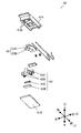
- FIG. 4 is an exploded perspective view of the input device shown in FIG.
- FIG. 5 is a diagram illustrating the configuration of the keypad and the driver in the input device shown in FIG.
- FIG. 6 is a circuit block diagram of the input device shown in FIG.
- FIG. 7 is a front view of an input device according to a modified example of the present disclosure.
- FIG. 8 is a sectional view taken along line 8-8 of the input device shown in FIG.
- FIG. 9 is a cross-sectional view taken along line 9-9 of the input device shown in FIG.
- FIG. 10 is a front view of the power generation unit in the input device shown in FIG. 11 is a cross-sectional view of the power generation unit shown in FIG. 10 taken along line 11-11.
- 12 is a cross-sectional view taken along line 12-12 of the power generation unit shown in FIG.
- FIG. 13 is an exploded perspective view of the power generation unit shown in FIG.
- the conventional input device has a configuration in which the link mechanism has the first link lever and the second link lever, the configuration becomes complicated. Therefore, there is a problem that the input device is large.
- the driving body having the sensor unit also serves as a part of the mechanism for vibrating the piezoelectric element, the mechanism for generating power is simple. Therefore, a small input device can be realized.
- FIG. 1 is a perspective view of the input device 1001.
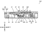
- FIG. 2 is a cross-sectional view of the input device 1001.
- FIG. 3 is a cross-sectional view when the input device 1001 is pressed.
- FIG. 4 is an exploded perspective view of the input device 1001. 2 and 3 are cross-sectional views taken along line 2-2 shown in FIG.
- the input device 1001 is a wireless remote controller, for example.
- the input device 1001 may be, for example, a wired remote controller.
- the input device 1001 not only transmits predetermined data assigned to a button operated by the operator, but also is connected to a device that measures the usage amount of gas or electricity, for example, and is operated by an operation by the operator.
- the generated power can be used as a device for transmitting data including the usage amount.
- the input device 1001 includes a keypad 20, a drive body 21, a power generation unit 22, a control unit 23, an activation unit 24, and a transmission unit 28.
- a plurality of sensor portions 21 ⁇ / b> A are formed on the drive body 21.
- the power generation unit 22 includes a piezoelectric element 22A.
- An activation unit 24 is disposed on the lower surface of the drive body 21.
- the starter 24 joined to the driving body 21 moves in the first direction.
- the starting unit 24 releases the load after bending the first end (downward) of the piezoelectric element 22A with a load in the first direction. Thereby, the piezoelectric element 22A of the power generation unit 22 vibrates to generate electric power.
- the control unit 23 is driven by the electric power generated by the power generation unit 22. Furthermore, 21 A of sensor parts detect the input operation (press operation to 20 A of operation buttons) by an operator using the electric power which the electric power generation part 22 generated, and output a detection signal. The detection signal is input to the control unit 23. The control unit 23 outputs a signal corresponding to the input detection signal to the transmission unit 28. And the transmission part 28 transmits the output signal according to a detection signal to the outward.
- the input device 1001 is configured such that the drive body 21 having the sensor unit 21A slides in the first direction by an input operation by the operator. That is, the drive body 21 that detects the input operation of the operator also serves as part or all of the mechanism for generating the power generation unit 22. Therefore, the input device 1001 can be downsized because the mechanism for power generation can be simplified.
- the input device 1001 includes a housing 26, a keypad 20, a driving body 21, a power generation unit 22, a control unit 23, an activation unit 24, a transmission unit 28, a slide mechanism unit 40, and a screw 30.
- the slide mechanism unit 40 may be composed of the pantograph mechanism 25 and the spring 29.
- the keypad 20, the drive body 21, the power generation unit 22, the control unit 23, the activation unit 24, the transmission unit 28, and the slide mechanism unit 40 are accommodated in the housing 26. A part of the keypad 20 is exposed from the housing 26.
- the housing 26 includes an upper housing 26A and a lower housing 26B as shown in FIG.
- the upper housing 26A and the lower housing 26B are joined by screws 30.
- the upper housing 26A and the lower housing 26B may be joined not only by the screws 30 but also by welding or a snap structure.
- the upper housing 26A has a plurality of through holes 26C.
- the keypad 20 is made of rubber, for example, and is an elastic body. As shown in FIG. 4, the keypad 20 is formed with a plurality of operation buttons 20A protruding upward with respect to the plate-like base body 20C. Further, as shown in FIG. 5, a conductive portion 20B is formed on the lower surface of the keypad 20 at a position corresponding to the operation button 20A. The conductive portion 20B is formed of a conductive material such as a carbon-based material. The upper part of the operation button 20A protrudes outward from the through hole 26C of the upper housing 26A. The operator performs a predetermined input to the input device 1001 by pressing the operation button 20A.
- the operation button 20A is not limited to the configuration protruding from the upper surface of the upper casing 26A, and may be configured to be recessed from the upper surface of the upper casing 26A.
- Various displays (not shown) are formed on the upper surface of the operation button 20 ⁇ / b> A of the keypad 20. With this configuration, the operator can visually recognize the display and operate the operation button 20A.
- the drive body 21 is a flat plate-like member disposed below the keypad 20.
- the drive body 21 is held by a slide mechanism section 40 described later so that the drive body 21 can slide up and down within the housing 26. That is, the driving body 21 slides in the first direction (downward direction) and the second direction (upward direction).
- the drive body 21 has a plurality of sensor units 21A that detect pressing operations of the operation buttons 20A by the operator.
- the upper surface of the driver 21 is preferably flat. Therefore, the driving body 21 is preferably flat.
- the drive body 21 in this Embodiment is a plate-shaped wiring board, for example, is made from an epoxy resin. Below, the structure of the keypad 20 and the drive body 21 is demonstrated in detail.
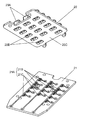
- FIG. 5 is an exploded perspective view of the keypad 20 and the drive body 21.
- the conductive portion 20B is formed on the lower surface of the keypad 20 at a position corresponding to the operation button 20A.
- sensor portions 21A are formed at positions corresponding to the conductive portions 20B of the keypad 20, respectively.
- the sensor unit 21A and the conductive unit 20B face each other at a predetermined interval. That is, the sensor unit 21A and the conductive unit 20B are not in contact.
- the sensor unit 21A includes a first electrode 21B and a second electrode 21C.
- the first electrode 21B and the second electrode 21C are wiring patterns formed in a predetermined shape on the wiring board, and are made of a metal material such as copper.
- the surface of the wiring pattern preferably has metal plating. For example, gold or silver can be used as a material for metal plating.
- the operation button 20A moves downward, and the conductive portion 20B and the sensor portion 21A come into contact with each other. That is, the conductive portion 20B is in contact with the first electrode 21B and the second electrode 21C. Thereby, the first electrode 21B and the second electrode 21C are electrically connected to each other.
- the drive body 21 is held so as to be slidable up and down by a slide mechanism section 40 described later, the operation button 20A is further pushed from the state where the conductive section 20B is in contact with the first electrode 21B and the second electrode 21C. When pushed down, the driving body 21 slides downward together with the operated operation button 20A.
- the input device 1001 is configured such that when any one of the plurality of operation buttons 20A is pressed down, the driving body 21 slides downward. Note that only the operation button 20A that has been pressed down slides downward on the keypad 20.
- the power generation unit 22 is disposed below the driving body 21 as shown in FIG.
- the power generation unit 22 includes a piezoelectric element 22A fixed in a cantilever shape.
- the piezoelectric element 22A is an element in which a piezoelectric material is formed in a thin plate shape on a thin metal plate, and generates electricity by deformation such as vibration.
- the metal plate is preferably a metal material having spring properties such as stainless steel. For example, it is preferable that the piezoelectric material is formed on both surfaces of a metal plate because the power generation amount can be improved.
- the piezoelectric material may be formed only on one side of the metal plate.
- the power generation unit 22 is fixed to the lower housing with screws or the like.
- the adsorbent 22B is fixed to the tip of the piezoelectric element 22A configured in a cantilever shape, and adsorbs to an activation unit 24 described later.
- the adsorbent 22B is, for example, a magnet.
- the starting portion 24 is a member formed of a plate-shaped metal material in a predetermined shape, and is formed through a fixed portion 24A fixed to the lower surface of the driving body 21 and an L-shaped step from the fixed portion 24A. It has a suction part 24B. As illustrated in FIG. 4, the suction portion 24B is located below the fixed portion 24A. The adsorption portion 24B is cut out in a U shape.
- the starter 24 is fixed to the lower surface of the drive body 21 and slides downward together with the drive body 21.
- the starting part 24 is a ferromagnetic body such as iron, and the upper surface of the attracting part 24B is attracted to the attracting body 22B (magnet) attached to the tip of the piezoelectric element 22A.
- the slide mechanism unit 40 slides the drive body 21 in the vertical direction.
- the slide mechanism unit 40 is accommodated in a gap between the driving body 21 and the lower housing 26B.
- the slide mechanism unit 40 for example, the pantograph mechanism 25 can be used.
- the slide mechanism unit 40 is connected to the drive body 21.
- the slide mechanism unit 40 preferably includes a spring 29.
- the spring 29 pushes up the driving body 21 upward.
- the driving body 21 returns to the initial position by the elastic force of the spring 29.
- the operation button 20A is made of rubber having elasticity, it can be restored to a shape protruding upward by its own restoring force after being bent downward by a pressing operation. Therefore, the keypad 20 can return to a state where the conductive portion 20B and the sensor portion 21A (the first electrode 21B and the second electrode 21C) do not contact each other.
- the spring 29 is compressed.
- the first electrode 21 ⁇ / b> B and the second electrode 21 ⁇ / b> C shown in FIG. 5 are pressed against the conductive portion 20 ⁇ / b> B of the keypad 20 by the reaction force of the spring 29. Therefore, the contact between the conductive portion 20B and the sensor portion 21A (the first electrode 21B and the second electrode 21C) is stabilized.
- the input device 1001 simplifies the mechanism for generating power by vibrating the piezoelectric element 22A of the power generation unit 22. Below, the operation
- the operation button 20A moves downward.
- the conductive portion 20B of the operation button 20A and the sensor unit 21A come into contact with each other.
- the first electrode 21B and the second electrode 21C are electrically connected.
- the drive body 21 slides downward as shown in FIG.
- the starting part 24 is joined to the driving body 21, it slides downward together with the driving body 21.
- the piezoelectric element 22A Since the piezoelectric element 22A is attracted to the activation part 24 by magnetic force, the tip of the piezoelectric element 22A bends downward as the activation part 24 slides. Then, when the restoring force that the piezoelectric element 22A that is bent downward returns to the original state becomes larger than the attracting force by the magnetic force, the piezoelectric element 22A moves away from the starter 24 and starts to vibrate. That is, the starting unit 24 vibrates the piezoelectric element 22 ⁇ / b> A by releasing the load after bending the piezoelectric element 22 ⁇ / b> A of the power generation unit 22 with a load. The power generation unit 22 generates power when the piezoelectric element 22A vibrates. The power generated by the power generation unit 22 is alternating current.
- the input device 1001 can generate power by an operator's input operation.
- the generated power is supplied to the drive body 21 (wiring board) or the like, and is used as drive power for the control unit 23 or the like mounted on the drive body 21.
- the operator receives a restoring force generated by the bending of the piezoelectric element 22A until the starting unit 24 and the power generation unit 22 are separated. That is, the operator receives a force pushing up from the operation button 20A in the second direction (upward).
- the driving body 21 is released from the restoring force due to the bending of the power generation unit 22. Accordingly, the force that pushes the operation button 20A upward decreases. Thereby, the operator gets an operation feeling.
- the operator can acquire an operation feeling reliably.
- the control unit 23 and the transmission unit 28 are arranged on the lower surface of the driving body 21 as shown in FIG. Note that both the control unit 23 and the transmission unit 28 are driven using the power generated by the power generation unit 22.
- a detection signal output from the sensor unit 21A is input to the control unit 23.
- the control unit 23 outputs a signal corresponding to the input detection signal to the transmission unit 28.
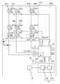
- FIG. 6 is a circuit block diagram of the input device 1001.
- Smn is the sensor unit 21A.
- Xmn is the first electrode 21B
- Ymn is the second electrode 21C.
- the control unit 23 has an output terminal 231 and an input terminal 232.
- the first electrode 21B (Xmn) of the sensor unit 21A (Smn) is electrically connected to the output terminal 231 of the control unit 23.
- the second electrode 21 ⁇ / b> C (Ymn) of the sensor unit 21 ⁇ / b> A (Smn) is electrically connected to the input terminal 232.
- the control unit 23 is mounted on the lower surface of the driving body 21 (wiring board) as shown in FIG.
- the control unit 23 is not limited to the configuration mounted on the lower surface of the drive body 21, and may be mounted on the upper surface of the drive body 21. Or the structure by which the control part 23 was mounted in the wiring board different from the drive body 21 may be sufficient.
- the control unit 23 sequentially outputs a predetermined signal from the output terminal 231 to the first electrode 21B (Xmn).
- the sensor unit 21A (Smn) is output from the output terminal 231.
- the predetermined signal is output as a detection signal. That is, a predetermined signal output from the output terminal 231 is input to the input terminal 232 as a detection signal via the sensor unit 21A (Smn). With this configuration, the control unit 23 can determine which operation button 20A the operator has operated.
- control part 23 has the output terminal 235 connected to the transmission part 28, as shown in FIG.
- An output signal from the output terminal 235 is input to the transmission unit 28.
- the transmission unit 28 is, for example, an infrared light emitting element.
- the output signal from the output terminal 235 is converted into an optical signal by the transmission unit 28 and transmitted to a receiver (not shown).
- the transmitting unit 28 is not limited to the infrared light emitting element, but may be a radio wave transmitting element.
- the output signal from the output terminal 235 is converted into a radio signal by the transmission unit 28.
- the transmission unit 28 transmits an output signal corresponding to the detection signal of the sensor unit 21A using the power generated by the power generation unit 22.
- the input device 1001 further includes a power storage unit 27.
- the power storage unit 27 is mounted on the drive body 21 (wiring board).
- the power storage unit 27 is electrically connected to the power generation unit 22 and stores power generated by the power generation unit 22.
- the power storage unit 27 is electrically connected to the power supply terminal 233 of the control unit 23 and supplies the power stored in the power storage unit 27 to the control unit 23.
- Power storage unit 27 includes a power storage element 27A and a rectifier circuit 27B.
- the power storage element 27A is, for example, a capacitor. Since the electric power generated by the piezoelectric element 22A is alternating current, the power storage unit 27 stores the power in the power storage element 27A after converting the power into direct current by the rectifier circuit 27B.
- the operation buttons 20A and the sensor units 21A are arranged in three rows in the X direction (right direction) and four rows in the Y direction (forward direction). In the rows at both ends in the X direction, five operation buttons 20A are arranged in the Y direction. That is, the number of operation buttons 20A in the rows at both ends in the X direction is one more than the number of operation buttons 20A in the center row in the X direction. Therefore, in the input device 1001, a total of 14 operation buttons 20A are arranged.
- the sensor units 21A are arranged in m columns in the X direction and n columns in the Y direction will be described. In this case, as shown in FIG.
- the driving body 21 has a sensor section 21A of S11 to Smn.
- the control unit 23 preferably includes a nonvolatile memory 234.
- the non-volatile memory 234 has a memory area that can specify which one of the sensor units S11 to Smn has been operated. Therefore, the non-volatile memory 234 preferably includes a plurality of memory areas.
- the sensor unit 21A (Smn) has an X electrode Xmn and a Y electrode Ymn.
- the sensor unit 21A (S11) includes an X electrode X11 and a Y electrode Y11.
- the X electrodes Xm1 to Xmn are all electrically connected.
- the Y electrodes Y1n to Ymn are all electrically connected.
- the control unit 23 preferably includes m output terminals 231 and n input terminals 232.
- the output terminal 231 includes output terminals OUT1 to OUTm.
- the input terminal 232 includes input terminals IN1 to INn.
- the X electrodes Xm1 to Xmn are each connected to the output terminal OUTm.
- the Y electrodes Y1n to Ymn are each connected to the input terminal INn.
- the X electrodes X11 to Xmn are, for example, the first electrodes 21B shown in FIG.
- the Y electrodes Y1n to Ymn are, for example, the second electrodes 21C shown in FIG.
- the conductive part 20B of the keypad 20 shown in FIG. 5 contacts the 1st electrode 21B and the 2nd electrode 21C by an operator's pressing operation.
- the sensor units Sm1 to Smn do not need to be arranged in a line in the Y direction. Further, the sensor units S1n to Smn do not need to be arranged in a line in the X direction. That is, the operation buttons 20A and the sensor unit 21A (Smn) need not be arranged in a grid pattern. That is, it is only necessary to detect which of the sensor units S11 to Smn is operated by the control unit 23, and the arrangement of the operation button 20A and the sensor unit 21A (Smn) is not limited.
- control unit 23 is not limited to the configuration having the m output terminals 231 and the n input terminals 232, and may include the n output terminals 231 and the m input terminals 232.
- the output terminal 231 includes output terminals OUT1 to OUTn.
- the input terminal 232 includes input terminals IN1 to INm.
- the X electrodes Xm1 to Xmn are connected to the input terminal INm.
- the Y electrodes Y1n to Ymn are connected to the output terminal OUTn.
- the operation of the input device 1001 will be described in more detail.
- the operator operates the operation button 20A corresponding to the sensor unit S22 illustrated in FIG. 6
- the conductive portion 20B of the keypad 20 comes into contact with the sensor portion S22. That is, the X electrode X22 and the Y electrode Y22 are electrically connected.
- the piezoelectric element 22A of the power generation unit 22 starts to vibrate.
- the electric power generated by the power generation unit 22 is supplied to the power storage unit 27.
- the power storage unit 27 converts the generated power into a constant voltage and supplies it to the control unit 23. Thereby, the control part 23 starts a drive.
- the control unit 23 outputs a predetermined output signal in the order of the output terminals OUT1 to OUTn.
- the output signal is, for example, a DC voltage signal having a predetermined voltage V1.
- the control unit 23 detects whether or not the sensor units S11 to Smn output detection signals in the order of the input terminals IN1 to INm. More specifically, the control unit 23 determines whether or not the output signal has returned to the control unit 23 in the order of the input terminals IN1 to INn while outputting the output signal from one output terminal OUTn. judge.
- the control unit 23 detects the predetermined voltage V1 (Hi) only at the input terminal IN2 among the input terminals IN1 to INm. Note that the voltages of the input terminals other than the input terminal IN2 are 0 V (Low). Therefore, the control part 23 can detect that the operator performed input operation with respect to sensor part S22.
- control unit 23 sequentially stores the detection results from the input terminals IN1 to INn in the nonvolatile memory 234. That is, as soon as the operation starts, the control unit 23 outputs an output signal from the output terminal 231 and performs an input determination operation of detecting the detection signal at the input terminal 232. Note that it is preferable that the control unit 23 does not perform other work during the input determination work. With this configuration, even when the operator quickly operates the operation button 20A, the control unit 23 can reliably detect the operation of the operator.
- the driving body 21 only needs to be able to detect an input operation by the operator, and may be, for example, a capacitive touch sensor or a touch panel.
- the touch panel may be either a capacitance type or a resistance film type. Moreover, what is necessary is just to be able to detect the input operation by the operator, and the input operation is not limited to the pressing operation.
- the adsorbent 22B of the power generation unit 22 also functions as a weight that assists the vibration of the piezoelectric element 22A.
- the metal plate of the piezoelectric element 22A is formed of stainless steel, for example. Since stainless steel is generally a non-magnetic material, it is preferable to use a magnet for the adsorbent 22B.
- the casing 26 is preferably formed of a resin material. Note that the entire housing 26 need not be made of resin. A metal material may be used for a part of the housing 26 as long as it does not hinder the adsorption by the adsorbent 22B. Moreover, it is preferable to form the starting part 24 with a magnetic material.
- the starting unit 24 is made of a nonmagnetic material
- an adsorbing body (not shown) may be attached to the starting unit 24.
- the adsorbent 22 ⁇ / b> B is disposed to face the adsorbent attached to the activation unit 24.
- the attracting member of the activation unit 24 is a magnetic material or a magnet.
- the lower housing 26B preferably includes a separation portion 26D.
- the activation unit 24 can slide to the lower side than the upper surface of the separation unit 26D.
- the power generation unit 22 comes into contact with the upper surface of the separation unit 26D and is restricted from moving downward. That is, the separation part 26D can suppress variation in the position where the starting part 24 and the piezoelectric element 22A are separated. Accordingly, the amplitude of the piezoelectric element 22A is stabilized. As a result, the power generation amount of the power generation unit 22 is stabilized. In addition, variations in the operation feel felt by the operator can be reduced.
- the separation unit 26D may be omitted.
- the restoring force of the piezoelectric element 22A increases as the amount of deflection of the power generation unit 22 increases. Then, when the reaction force of the piezoelectric element 22A becomes larger than the attracting force due to the magnetic force, the power generation unit 22 moves away from the activation unit 24 and starts to vibrate.
- the power generation unit 22 may have a configuration in which both ends of the piezoelectric element 22A are fixed.
- the adsorbent 22B is attached to the center of the piezoelectric element 22A.
- the center part of the electric power generation part 22 is adsorbed by the starting part 24, and the central part of an electric power generation part is bent.
- the starter 24 may generate power by flipping the tip of the piezoelectric element 22A to vibrate.
- the piezoelectric element 22A of the power generation unit 22 may be partially bent regardless of the flat plate shape.
- the entire power generation unit 22 may not be configured to be accommodated in the gap between the driving body 21 and the lower surface of the lower housing 26B. That is, the power generation unit 22 may be disposed so as to straddle the gap.
- the input device 1001 may reverse the arrangement of the power generation unit 22 and the activation unit 24. That is, the power generation unit 22 is joined to the drive body 21.
- the starting unit 24 is joined to the lower housing 26B.
- the power generation unit 22 slides as the drive body 21 moves.
- the piezoelectric element 22 ⁇ / b> A of the power generation unit 22 is vibrated by the activation unit 24. Even if it is the above structure, the drive body 21 becomes a structure which served as the mechanism for making the electric power generation part 22 generate electric power.
- the sensor unit 21A is configured to detect an input operation by electrically connecting the first electrode 21B and the second electrode 21C.
- the sensor unit 21A is not limited to this configuration, and a switch (not shown) or the like is used. Also good.
- the switch is mounted on the upper surface of the driver 21 (wiring board) by soldering or the like.
- the switch is switched by a predetermined operating force (pressing force). Further, the switch has an operation feeling when a pressing operation is performed. Therefore, it is preferable that the operation feeling by the piezoelectric element 22A of the power generation unit 22 is larger than the operation feeling of the switch.
- This configuration makes it difficult for the operator to feel the operation feeling of the switch alone. Therefore, the operator can be prevented from receiving the operation feeling of the switch alone and ending the operation of pressing down the operation button 20A. That is, it can be suppressed that the operator misunderstands that the input operation is completed before the power generation unit 22 generates power.
- the sensor unit 21A may be a membrane switch. Alternatively, the sensor unit 21A may be an electrostatic touch sensor. Further, the driving body 21 may include the keypad 20.
- the drive body 21 may be configured by a touch panel (not shown), for example. That is, the operator can input to the input device 1001 by operating the surface of the touch panel. Therefore, the operation area of the touch panel is exposed from the through hole 26C.
- the touch panel may be either a capacitance type or a resistance film type. That is, the input device 1001 can generate power with the same configuration as described above even when a touch panel is used as the driver 21.
- the drive unit 21 may directly vibrate the power generation unit 22. That is, the drive body 21 and the starting part 24 may be integrated. In this case, the drive body 21 also serves as the activation unit 24. With this configuration, the drive body 21 vibrates the power generation unit 22.
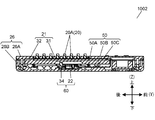
- FIG. 7 is a top view of the input device 1002.
- FIG. 8 is a cross-sectional view of the input device 1002.
- FIG. 8 shows a state in which the input device 1002 is cut along a sectional line 8-8 in FIG.
- An input device 1002 is a modification of the input device 1001 shown in FIG.
- the input device 1002 includes a slide mechanism unit 50. That is, the input device 1002 includes a slide mechanism unit 50 instead of the slide mechanism unit 40 shown in FIG.
- the input device 1001 shown in FIG. 1 may use the slide mechanism unit 50 shown in FIG. 8 instead of the slide mechanism unit 40 shown in FIG.
- the slide mechanism 50 has a pin 50B and a bearing 50C.
- the slide mechanism 50 preferably has a spring 50A.
- the pin 50B is inserted into the bearing 50C.
- the bearing 50C can slide and move in the vertical direction.
- the bearing 50 ⁇ / b> C is joined to the drive body 21. That is, the driving body 21 is held so as to be slidable in the vertical direction.
- the bearing 50C passes through the drive body 21.
- the pin 50B is joined to the housing 26.
- the first end of the pin 50B is joined to the upper casing 26A, and the second end is joined to the lower casing 26B.
- the thickness of the driving body 21 is thick. With this configuration, it is possible to prevent the bearing 50C from being attached to the drive body 21 in an inclined manner. Therefore, it can suppress that the drive body 21 inclines and slides. Therefore, the drive body 21 can move up and down smoothly.
- the driving body 21 includes a wiring board 31 and a reinforcing part 32.
- the slide mechanism unit 50 is not limited to the above-described configuration, and may be configured by a guide protrusion (not shown) and a guide groove (not shown), for example.
- a guide protrusion is provided on the outer peripheral side surface of the drive body 21.
- the guide protrusion protrudes in a direction facing the side surface of the lower housing 26B.
- a guide groove is provided inside the side surface of the lower housing 26B.
- the guide groove guides the guide protrusion in the vertical direction.
- the guide protrusion may be provided inside the side surface of the lower housing 26B.
- the guide groove is formed on the outer peripheral side surface of the drive body 21.
- FIG. 9 is a cross-sectional view of the input device 1002.
- FIG. 9 shows a state in which the input device 1002 is cut along a sectional line 9-9 in FIG.
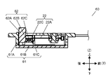
- FIG. 10 is a front view of the power generation unit 60.
- 11 and 12 are cross-sectional views of the power generation unit 60.
- FIG. 11 shows a state in which the power generation unit 60 is cut along a sectional line 11-11 in FIG.
- FIG. 12 shows a state where the power generation unit 60 is cut along a sectional line 12-12 in FIG.
- FIG. 13 is an exploded perspective view of the power generation unit 60.
- the input device 1002 has a power generation unit 60 instead of the power generation unit 22 shown in FIG.
- the power generation unit 60 includes an activation unit 62 and a power generation unit 22. That is, the input device 1002 includes an activation unit 62 instead of the activation unit 24.
- the power generation unit 60 further includes a sub case 61.
- the sub case 61 has an upper sub case 61A and a lower sub case 61B.
- the separation portion 26D is formed in the lower sub case 61B.
- the separation part 26D is not limited to the configuration formed in the lower sub case 61B, and may be provided in the lower housing 26B.
- the power generation unit 60 is modularized by housing the power generation unit 22 and the activation unit 62 in the sub case 61. Note that all or part of the subcase 61 may be integrated with the housing 26.
- the starting unit 62 is separated from the driving body 21.
- the starter 62 is in contact with the drive body 21 but is not joined.
- the starter 62 moves downward in contact with the drive body 21 as the drive body 21 moves downward. That is, the lower surface of the drive body 21 pushes the starting part 62 downward by a pressing operation by the operator. And the starting part 62 can move below with the drive body 21. Since the starting unit 62 is separated from the driving body 21, it is difficult to be affected by the displacement of the driving body 21 or the inclination of the direction in which the driving body 21 slides. Thereby, the drive body 21 can move to an up-down direction stably. Therefore, the power generation amount of the power generation unit 22 is also stabilized.
- the starter 62 is adsorbed to the power generation unit 22 by magnetic force, like the starter 24. Therefore, when the operator performs a pressing operation, the piezoelectric element 22A bends downward. Then, the piezoelectric element 22A is detached from the starting unit 62 and vibrates. When the pressing operation by the operator is released, the piezoelectric element 22A detached from the piezoelectric element 22A is attracted to the power generation unit 22 by the magnetic force and restored to the state of being adsorbed with the piezoelectric element 22A.
- the power generation unit 60 preferably includes a guide pin 61D and a guide hole 61C as shown in FIG.
- the guide pin 61D is inserted into the guide hole 61C.
- the guide pin 61D is not limited to the configuration penetrating the guide hole 61C, and may be halfway.
- the guide hole 61C is not limited to the through hole, and may be a bottomed hole.
- the configuration is not limited to the configuration in which the guide pin 61D is provided in the sub case 61 and the guide hole 61C is provided in the starting portion 62. That is, the guide pin 61D may be provided in the starting part 62, and the guide hole 61C may be provided in the sub case 61. Alternatively, the guide hole 61C and the guide pin 61D may be provided in the housing 26.
- the activation unit 62 preferably includes an activation button 62A and an adsorbent 62C.
- the adsorbent 62C is fixed to the start button 62A.
- a part of the start button 62 ⁇ / b> A penetrates the upper sub case 61 ⁇ / b> A and protrudes from the sub case 61.
- the activation button 62A can be formed of a resin material. With this configuration, the activation unit 62 can be lightened. Therefore, the starting unit 62 can quickly return to the initial position by the adsorption force between the adsorbent 22B and the adsorbent 62C.
- the activation button 62A is not limited to the configuration formed of a resin material, and all or part of the activation button 62A may be formed of a metal material. However, in this case, it is preferable to use a nonmagnetic material for the activation button 62A.
- the adsorbent 62C is formed of a magnet.
- the starting part 62 further includes a yoke 62B.
- the yoke 62B is provided opposite to the surface of the adsorbent 62C that faces the adsorbent 22B.
- the starting part 62 can be reduced, when the pressing operation by the operator is released, the starting part 62 can be attracted to the adsorbing body 22B by the magnetic force of the adsorbing body 62C. As a result, the starting unit 62 returns to the initial position.
- a buffer member (not shown) on either the lower surface of the adsorbent 22B or the upper surface of the adsorbent 62C.
- the input device 1002 is not limited to the configuration including both the slide mechanism unit 50 illustrated in FIG. 8 and the power generation unit 60 illustrated in FIG. 9, and may include only one of them. Further, the input device 1001 shown in FIG. 1 may include a power generation unit 60 instead of the power generation unit 22 shown in FIG.
- the driving body 21 preferably includes a wiring board 31.
- the control unit 23 and the power storage unit 27 are generally mounted on the wiring board 31. That is, electronic components such as the control unit 23 and the power storage unit 27 shown in FIG. 1 are mounted on the wiring board 31 by reflow soldering or the like.
- the drive body 21 preferably includes a reinforcing portion 32. By mounting the wiring board 31 on the upper surface of the reinforcing portion 32, unnecessary warping and deformation of the wiring board 31 can be suppressed.
- the wiring board 31 is fixed to the reinforcing portion 32 with screws, an adhesive, or the like. With this configuration, the wiring board 31 is fixed along the upper surface of the reinforcing portion 32. As a result, variation in stroke length of the operation button 20A can be reduced.
- the input devices 1001 and 1002 of the present disclosure include a driving body 21 including a sensor unit 21A and a power generation unit 22 including a piezoelectric element 22A.
- the sensor unit 21A detects the operation of the operator and outputs a detection signal.
- the driving body 21 slides in the first direction by the operation of the operator.
- the piezoelectric element 22 ⁇ / b> A of the power generation unit 22 vibrates when the drive body 21 slides in the first direction. Thereby, the power generation unit 22 generates power.
- 21 A of sensor parts output a detection signal using the electric power which the electric power generation part 22 generated.
- the input device 1001 includes an activation unit 24 that vibrates the piezoelectric element 22A of the power generation unit 22 based on the sliding movement of the driving body 21 in the first direction.
- the input device 1002 includes an activation unit 62 that vibrates the piezoelectric element 22A of the power generation unit 22 based on the sliding movement of the driving body 21 in the first direction.
- the activation units 24 and 62 vibrate the piezoelectric element 22A by releasing the load after bending the piezoelectric element 22A of the power generation unit 22 with a load.
- the starting unit 24 is joined to the drive body 21.
- the starting unit 24 slides in the first direction together with the driving body 21.
- the input device 1001 further includes a slide mechanism 40 that slides the drive body 21 that has been slid in the first direction in the second direction.
- the drive body 21 has a plate shape having a plane intersecting the second direction, and the sensor portion 21A is formed on the plane.
- the slide mechanism unit 40 is a pantograph mechanism that slides in the second direction while maintaining the inclination of the drive body 21.
- the slide mechanism unit 40 includes a spring 29 that pushes the drive body 21 in the second direction.
- the input device 1002 further includes a slide mechanism unit 50 that slides the drive body 21 that has been slid in the first direction in the second direction.
- the slide mechanism unit 50 includes a spring 50A that pushes the driving body 21 in the second direction.
- the sensor unit 21A includes a first electrode 21B and a second electrode 21C that is electrically independent of the first electrode 21B.
- the sensor unit 21A outputs a detection signal when the first electrode 21B and the second electrode 21C are electrically connected by an input operation of the operator.
- the driver 21 may be formed with a plurality of sensor units 21A.
- the driving body 21 slides in the first direction even when any one of the plurality of sensor units 21A is operated.
- the input devices 1001 and 1002 further include a control unit 23 that is driven using the power generated by the power generation unit 22.
- the control unit 23 includes an input terminal 232 to which detection signals output from the plurality of sensor units 21 ⁇ / b> A are input, and a nonvolatile memory 234. Based on the detection signal input to the input terminal 232, the control unit 23 stores information on which sensor unit 21 ⁇ / b> A of the plurality of sensor units 21 ⁇ / b> A has been operated in the nonvolatile memory 234.
- the input devices 1001 and 1002 further include a transmission unit 28 that is driven using the power generated by the power generation unit 22.
- the transmission part 28 transmits the output signal according to the detection signal of 21 A of sensor parts using the electric power which the electric power generation part 22 generated.
- the input devices 1001 and 1002 have a configuration in which the drive body 21 also serves as a part of the mechanism for generating the power generation unit 22, the mechanism for vibrating the power generation unit 22 is simple. Therefore, it is possible to generate power with a simple structure. As a result, a small input device can be realized.
- the input device has an effect that a small input device can be realized, and is useful when used for a power generation type remote controller having a plurality of operation buttons.
Landscapes
- Input From Keyboards Or The Like (AREA)
- Push-Button Switches (AREA)
Abstract
入力装置は、センサ部を有した駆動体と、圧電素子を有した発電部と、を有する。駆動体は、操作者の操作によって第1方向にスライド移動する。駆動体は、圧電素子を振動させる機構の一部または全てを兼ねている。したがって、発電部は、圧電素子が駆動体の第1方向へのスライド移動によって振動することで発電する。センサ部は、発電部が発電した電力を用いて、操作者の操作を検知して検知信号を出力する。これにより、入力装置は、簡素な構造によって圧電素子を振動させて発電することができる。
Description
本開示は、電子機器等に用いられる入力装置に関する。
以下、従来の入力装置について説明する。従来の入力装置は、例えば特許文献1に開示されている。特許文献1が開示する従来の入力装置は、筐体と、複数のスイッチキーと、複数のスイッチと、発電部と、複数のスイッチキーと発電部とを連結するリンク機構とを有する。リンク機構は、第1リンクレバーと第2リンクレバーを有する。スイッチキーと、スイッチと、発電部と、リンク機構は、筐体内に収納されている。なお、複数のスイッチキーのそれぞれの一部は、筐体から露出している。複数のスイッチキーのそれぞれは、スイッチキーの押し下ろし動作によってスイッチを押し下ろすピンを有する。リンク機構は、スイッチキーの押し下ろし動作を発電部に伝達する。発電部は、リンク機構によってスイッチキーの押し下ろし動作が伝達されて、発電する。つまり、従来の入力装置は、スイッチキーが操作者によって押圧操作されることで発電する。
本開示の入力装置は、センサ部を有した駆動体と、圧電素子を有した発電部と、を有する。駆動体は、操作者の操作によって第1方向にスライド移動する。発電部の圧電素子は、駆動体が第1方向へスライド移動することで振動する。発電部は圧電素子の振動によって発電する。センサ部は、発電部が発電した電力を用いて、操作者の操作を検知して検知信号を出力する。
この構成であれば、発電させるための機構が簡単であり、小さな入力装置を実現できる。
本開示の実施の形態の説明に先立ち、従来の入力装置における課題を簡単に説明する。
従来の入力装置は、リンク機構が第1リンクレバーと第2リンクレバーを有した構成であるため、構成が複雑となる。したがって、入力装置が大きいという課題を有している。
本開示の入力装置によれば、センサ部を有した駆動体が、圧電素子を振動させる機構の一部を兼ねた構成であるので、発電させるための機構が簡単である。したがって、小さな入力装置を実現できる。
以下、入力装置等の実施形態について図面を参照しながら説明する。なお、実施の形態において同じ符号を付した構成要素は同様の動作を行うので、再度の説明を省略する場合がある。
(実施の形態)
図1は、入力装置1001の斜視図である。図2は、入力装置1001の断面図である。図3は、入力装置1001を押圧操作したときの断面図である。図4は、入力装置1001の分解斜視図である。なお、図2および図3は、図1に示す2-2線における断面図である。
図1は、入力装置1001の斜視図である。図2は、入力装置1001の断面図である。図3は、入力装置1001を押圧操作したときの断面図である。図4は、入力装置1001の分解斜視図である。なお、図2および図3は、図1に示す2-2線における断面図である。
以下、入力装置1001について、主に図2を参照しながら説明する。入力装置1001は、例えば無線式のリモコンである。なお、入力装置1001は、例えば有線式のリモコンであってもよい。また、入力装置1001は、操作者が操作したボタンに割り当てられた所定のデータを送信するだけでなく、例えば、ガスまたは電気などの使用量を測定する装置に接続されて、操作者による操作によって発電した電力を用いて、当該使用量を含んだデータを送信するための機器として用いることもできる。
図2などに示すように、入力装置1001は、キーパッド20と駆動体21と発電部22と制御部23と起動部24と送信部28を有する。駆動体21には複数のセンサ部21Aが形成されている。発電部22は圧電素子22Aを有する。駆動体21の下面には起動部24が配されている。操作者がキーパッド20の操作ボタン20Aを入力操作(押圧操作)すると、図3に示すように、駆動体21が第1方向(下方向)へスライド移動する。つまり、駆動体21は、操作者の操作に応じて、第1方向へスライド移動する。そして、駆動体21の第1方向への移動と共に、駆動体21に接合された起動部24が第1方向へ移動する。起動部24は、圧電素子22Aの先端に第1方向(下方向)の荷重をかけて撓ませた後に、当該荷重を解除する。これにより、発電部22の圧電素子22Aが振動して電力を生成する。
制御部23は、発電部22が発電した電力によって駆動する。さらに、センサ部21Aは、発電部22が発電した電力を用いて操作者による入力操作(操作ボタン20Aへの押圧操作)を検知して検知信号を出力する。なお、検知信号は、制御部23へ入力される。制御部23は、入力された検知信号に応じた信号を送信部28に出力する。そして、送信部28は、検知信号に応じた出力信号を外方に送信する。
このように、入力装置1001は、操作者による入力操作によって、センサ部21Aを有した駆動体21が第1方向へスライド移動するように構成されている。つまり、操作者の入力操作を検知する駆動体21が、発電部22を発電させるための機構の一部または全部を兼ねている。したがって、入力装置1001は、発電のための機構が簡略化できるため、小型化することができる。
以下、入力装置1001の具体的な構成について詳細に説明する。入力装置1001は、筐体26とキーパッド20と駆動体21と発電部22と制御部23と起動部24と送信部28とスライド機構部40とネジ30を有する。スライド機構部40は、パンタグラフ機構25とバネ29で構成するとよい。キーパッド20と駆動体21と発電部22と制御部23と起動部24と送信部28とスライド機構部40は、筐体26内に収納されている。なお、キーパッド20の一部は、筐体26から露出している。
筐体26は、図2などに示すように、上筐体26Aと下筐体26Bを有する。上筐体26Aと下筐体26Bは、ネジ30によって接合されている。なお、上筐体26Aと下筐体26Bの接合は、ネジ30による接合だけでなく、溶着やスナップ構造によって互いが接合されてもよい。なお、上筐体26Aには、複数の貫通孔26Cが形成されている。
キーパッド20は、例えばゴムで形成され弾性体である。キーパッド20は、図4に示すように、板状の基体20Cに対して、上方に突出した複数の操作ボタン20Aが形成されている。さらに、図5に示すように、キーパッド20の下面には、操作ボタン20Aに対応する位置に、導電部20Bが形成されている。導電部20Bは、例えば炭素系の材料などの導電性を有した材料によって形成されている。操作ボタン20Aの上部が上筐体26Aの貫通孔26Cから外方に突出している。操作者は、操作ボタン20Aを押圧操作することで、入力装置1001に対して所定の入力を行う。
なお、操作ボタン20Aは、上筐体26Aの上面から突出していた構成に限られず、上筐体26Aの上面よりも凹んだ構成でもよい。なお、キーパッド20の操作ボタン20Aの上面には、各種表示(図示せず)が形成されている。この構成により、操作者は当該表示を視認して、操作ボタン20Aを操作できる。
駆動体21は、キーパッド20の下方に配された平板状の部材である。駆動体21は、後述するスライド機構部40によって、筐体26内で上下にスライド移動できるように保持されている。つまり、駆動体21は、第1方向(下方向)と第2方向(上方向)にスライド移動する。さらに、駆動体21は、操作者による操作ボタン20Aの押圧操作を検知するセンサ部21Aを複数有する。なお、駆動体21の上面は平坦であることが好ましい。そのために、駆動体21は平板状が好ましい。なお、本実施の形態における駆動体21は、板状の配線基板であり、例えばエポキシ樹脂製である。以下に、キーパッド20と駆動体21の構成について詳しく説明する。
図5は、キーパッド20と駆動体21の分解斜視図である。上述したように、キーパッド20の下面には、操作ボタン20Aに対応する位置に、導電部20Bが形成されている。駆動体21の上面には、キーパッド20の導電部20Bに対応する位置にセンサ部21Aがそれぞれ形成されている。センサ部21Aと導電部20Bは所定の間隔で対向している。つまり、センサ部21Aと導電部20Bは接触していない。センサ部21Aは、第1電極21Bと第2電極21Cとで構成されている。なお、第1電極21Bと第2電極21Cは、配線基板上に所定の形状で形成された配線パターンであり、銅などの金属材料で構成されている。さらに、当該配線パターンの表面は、金属メッキを有することが好ましい。なお、金属メッキの材料としては、例えば金や銀などを用いることができる。
ここに、操作者が操作ボタン20Aを押圧操作すると、操作ボタン20Aが下方に移動して、導電部20Bとセンサ部21Aが接触する。つまり、導電部20Bが第1電極21Bと第2電極21Cに接触する。これにより、第1電極21Bと第2電極21Cが互いに電気的に接続される。なお、駆動体21は、後述するスライド機構部40によって上下にスライド移動可能に保持されているため、導電部20Bが第1電極21Bと第2電極21Cと接触した状態から、さらに操作ボタン20Aを押し下ろすと、駆動体21は、操作された操作ボタン20Aと共に下方へとスライド移動する。
なお、入力装置1001は、複数の操作ボタン20Aのうち、いずれか一つの操作ボタン20Aを押し下ろせば、駆動体21が下方向へとスライド移動するように構成されている。なお、キーパッド20は、押し下された操作ボタン20Aのみが下方向へとスライド移動する。
発電部22は、図2に示すように、駆動体21の下方に配されている。発電部22は、片持ち梁状に固定された圧電素子22Aを有する。圧電素子22Aは、薄板状の金属板に、圧電材料が薄板状に形成された素子であり、振動などの変形によって発電する。金属板は、ステンレスなどのバネ性を有した金属材料が好ましい。圧電材料は、例えば金属板の両面に形成されていると発電量を向上できるので好ましい。なお、圧電材料は、金属板の片面のみに形成されていてもよい。発電部22は、下筐体にネジなどで固定されている。なお、片持ち梁状に構成された圧電素子22Aの先端には、吸着体22Bが固定されていて、後述する起動部24と吸着する。なお、吸着体22Bは、例えば磁石である。
起動部24は、板状の金属材料を所定の形状に形成した部材であり、駆動体21の下面に固定される固定部24Aと、固定部24AからL字状の段差を介して形成された吸着部24Bを有する。図4に示すように、吸着部24Bは、固定部24Aよりも下方に位置する。吸着部24Bは、U字状に切り欠かれている。起動部24は、駆動体21の下面に固定されていて、駆動体21と共に下方へとスライド移動する。なお、起動部24は、鉄などの強磁性体であり、吸着部24Bの上面が圧電素子22Aの先端に取り付けられた吸着体22B(磁石)と吸着している。
スライド機構部40は、駆動体21を上下方向へスライド移動させる。なお、スライド機構部40は、駆動体21と下筐体26Bとの間の空隙に収納されている。スライド機構部40としては、例えばパンタグラフ機構25を用いることができる。スライド機構部40は、駆動体21へ連結されている。このようにスライド機構部40を設けることにより、駆動体21がスライド移動する際の駆動体21の傾きを抑制できる。つまり、駆動体21は、スライド機構部40によって保持されることで、駆動体21の上面の傾きを維持したまま、上下方向にスライド移動できる。したがって、駆動体21は、傾くことなく安定してスライド移動することができる。つまり、いずれの操作ボタン20Aが押し下ろされても、駆動体21は、傾くことなく安定してスライド移動することができる。また、駆動体21に接合された起動部24も安定してスライド移動することができる。さらに、操作者が操作ボタン20Aを押し下ろしたときのストロークの長さも安定する。
また、スライド機構部40は、バネ29を含むことが好ましい。バネ29は、駆動体21を上方向へと押し上げている。この構成により操作者が、操作ボタン20Aの押圧操作を解除すると、バネ29の弾性力によって、駆動体21は初期の位置に復帰する。なお、操作ボタン20Aは、弾性を有したゴム製のため、押圧操作によって下方に撓んだ後、自己の復帰力で上方に突出した形状に復元することができる。したがって、キーパッド20は、導電部20Bとセンサ部21A(第1電極21Bと第2電極21C)が接触しない状態に戻ることができる。
また、操作者が操作ボタン20Aを押圧操作した際に、バネ29が圧縮される。この状態において、図5に示す第1電極21Bと第2電極21Cは、バネ29の反力によってキーパッド20の導電部20Bへと押しつけられる。したがって、導電部20Bとセンサ部21A(第1電極21Bと第2電極21C)の接触が安定する。
以上に説明した構成によって、入力装置1001は、発電部22の圧電素子22Aを振動させて発電させる機構を簡便化している。以下に、入力装置1001における発電の動作について説明する。
図2に示す状態から操作者が操作ボタン20Aを押圧操作すると、操作ボタン20Aは下方に移動する。操作ボタン20Aが下方に移動することによって、操作ボタン20Aの導電部20Bと駆動体21のセンサ部21A(第1電極21Bと第2電極21C)が接触する。これにより、第1電極21Bと第2電極21Cが電気的に接続される。導電部20Bとセンサ部21Aが接触した状態から、さらに操作ボタン20Aを押圧操作すると、図3に示すように、駆動体21が下方にスライド移動する。なお、起動部24は、駆動体21に接合されているので、駆動体21と共に下方にスライド移動する。圧電素子22Aは、磁力により起動部24と吸着しているので、起動部24のスライド移動に伴って、圧電素子22Aの先端が下方向きに撓む。そして、下方向きに撓んだ圧電素子22Aが元に戻ろうとする復元力が、磁力による吸着力よりも大きくなると、圧電素子22Aは起動部24から離れて、振動を開始する。つまり、起動部24は、発電部22の圧電素子22Aに荷重をかけて撓ませた後に、当該荷重を解除することによって圧電素子22Aを振動させている。発電部22は圧電素子22Aが振動することで発電する。なお、発電部22が発電する電力は交流である。
以上のように、入力装置1001は、操作者の入力操作により発電できる。なお、発電された電力は、駆動体21(配線基板)などに供給されており、駆動体21に実装されている制御部23などの駆動電力として用いられる。
なお、上述した押圧操作において、操作者は、起動部24と発電部22とが離脱するまでの間、圧電素子22Aの撓みによって発生する復元力を受ける。つまり、操作者は、操作ボタン20Aから第2方向(上方向)へと押し上げる力を受ける。発電部22が起動部24から離脱すると、駆動体21は、発電部22の撓みによる復元力から解放される。したがって、操作ボタン20Aを上方向へと押し上げる力が減少する。これにより、操作者は操作感触を得る。また、以上の構成であれば、導電部20Bとセンサ部21Aとが接触するまでの押圧操作における操作感触が小さくても、操作者は、確実に操作感触を得ることができる。
制御部23と送信部28は、図2などに示すように、駆動体21の下面に配されている。なお、制御部23と送信部28は、いずれも発電部22によって発電された電力を用いて駆動する。制御部23には、センサ部21Aが出力した検知信号が入力される。そして、制御部23は、入力された検知信号に応じた信号を送信部28に出力する。以下に、制御部23と送信部28の構成などについて、図6を用いて説明する。
図6は、入力装置1001の回路ブロック図である。なお、図6において、Smnはセンサ部21Aである。Xmnは第1電極21Bであり、Ymnは第2電極21Cである。図6に示すように、制御部23は、出力端子231と、入力端子232を有している。センサ部21A(Smn)の第1電極21B(Xmn)は、制御部23の出力端子231と電気的に接続されている。一方、センサ部21A(Smn)の第2電極21C(Ymn)は、入力端子232と電気的に接続されている。
制御部23は、図2に示すように、駆動体21(配線基板)の下面に実装されている。なお、制御部23は、駆動体21の下面に実装した構成に限られず、駆動体21の上面に実装されていてもよい。あるいは、駆動体21とは別の配線基板に制御部23が実装された構成でもよい。
制御部23は、出力端子231から所定の信号を第1電極21B(Xmn)に対して順次出力する。そして、操作ボタン20Aが押圧操作されて、第1電極21B(Xmn)と第2電極21C(Ymn)が電気的に導通している場合、センサ部21A(Smn)は、出力端子231から出力された所定の信号を検知信号として出力する。すなわち、出力端子231から出力された所定の信号が、センサ部21A(Smn)を介して、検知信号として入力端子232へと入力される。この構成により、制御部23は、操作者がどの操作ボタン20Aを操作したかを判定できる。
さらに、制御部23は、図6に示すように、送信部28に接続された出力端子235を有する。出力端子235からの出力信号は、送信部28に入力されている。送信部28は、例えば赤外線発光素子である。この場合、出力端子235からの出力信号は、送信部28によって光信号へと変換されて、受信機(図示せず)へと送信される。なお、送信部28は、赤外線発光素子に限られず、電波送信素子でもよい。この場合、出力端子235からの出力信号は、送信部28によって無線信号へと変換される。このように、送信部28は、発電部22が発電した電力を用いてセンサ部21Aの検知信号に応じた出力信号を送信する。
次に、入力装置1001において、操作者の操作を検知するための動作についてさらに詳しく説明する。図6に示すように、入力装置1001は、さらに蓄電部27を有する。蓄電部27は駆動体21(配線基板)に実装されている。蓄電部27は、発電部22に電気的に接続されていて、発電部22で発生した電力を蓄える。さらに、蓄電部27は、制御部23の電源端子233へ電気的に接続されていて、蓄電部27で蓄えた電力を制御部23に供給する。蓄電部27は、蓄電素子27Aと整流回路27Bを含む。蓄電素子27Aは、例えばコンデンサである。圧電素子22Aが発電する電力は交流であるため、蓄電部27は、整流回路27Bによって電力を直流に変換した後に蓄電素子27Aに電力を蓄える。
図4などに示すように、操作ボタン20Aおよびセンサ部21Aは、X方向(右方向)に3列、Y方向(前方向)に4列並んでいる。なお、X方向における両端の列においては、操作ボタン20AがY方向に5個配置されている。つまり、X方向における両端の列の操作ボタン20Aは、X方向における中央の列の操作ボタン20Aよりもそれぞれ1個多い。したがって、入力装置1001は、合計で14個の操作ボタン20Aが配列されている。以下、センサ部21Aが、X方向にm列、Y方向にn列配列されている入力装置1001を例にとって説明する。この場合、図6に示すように、駆動体21は、S11~Smnのセンサ部21Aを有する。また、制御部23は、不揮発性メモリ234を含むことが好ましい。なお、不揮発性メモリ234は、センサ部S11~Smnのうちのいずれが操作されたかを特定できるメモリ領域を有する。そのために、不揮発性メモリ234は、複数のメモリ領域を含むことが好ましい。
図6に示すように、センサ部21A(Smn)は、X電極XmnとY電極Ymnを有する。例えば、センサ部21A(S11)は、X電極X11とY電極Y11とを有する。なお、X電極Xm1~Xmnは、いずれも電気的に接続している。一方、Y電極Y1n~Ymnは、いずれも電気的に接続している。制御部23は、m個の出力端子231と、n個の入力端子232を含むことが好ましい。この場合、出力端子231は、出力端子OUT1~OUTmを含んでいる。一方、入力端子232は、入力端子IN1~INnを含んでいる。そして、X電極Xm1~Xmnは、それぞれ出力端子OUTmに接続されている。一方、Y電極Y1n~Ymnは、それぞれ入力端子INnに接続されている。なお、X電極X11~Xmnは、例えば図5に示す第1電極21Bである。一方、Y電極Y1n~Ymnは、例えば図5に示す第2電極21Cである。そして、操作者の押圧操作によって、図5に示すキーパッド20の導電部20Bが、第1電極21Bおよび第2電極21Cに接触する。
なお、センサ部Sm1~Smnは、Y方向に一列に並んでいる必要はない。また、センサ部S1n~Smnは、X方向に一列に並んでいる必要はない。すなわち、操作ボタン20Aとセンサ部21A(Smn)の配置は、格子状に配置されている必要はない。つまり、制御部23でセンサ部S11~Smnのいずれが操作されたかを検出できればよく、操作ボタン20Aとセンサ部21A(Smn)の配置に限定はない。
また、制御部23は、m個の出力端子231と、n個の入力端子232を有した構成に限られず、n個の出力端子231と、m個の入力端子232を含んでもよい。この場合、出力端子231は、出力端子OUT1~OUTnを含んでいる。一方、入力端子232は、入力端子IN1~INmを含んでいる。そして、X電極Xm1~Xmnは、入力端子INmに接続される。一方、Y電極Y1n~Ymnは、出力端子OUTnに接続される。
以下、入力装置1001の動作について、さらに詳しく説明する。操作者が例えば図6に示すセンサ部S22に対応する操作ボタン20Aを操作した場合を例にとって説明する。操作者が操作ボタン20Aを押し下ろすことにより、キーパッド20の導電部20Bがセンサ部S22に接触する。つまり、X電極X22とY電極Y22が電気的に接続される。操作者がさらに操作ボタン20Aを押し下ろすことによって、発電部22の圧電素子22Aが振動を開始する。発電部22が発電した電力は蓄電部27に供給される。そして、蓄電部27は、発電された電力を一定の電圧へと変換して、制御部23へ供給する。これにより、制御部23は駆動を開始する。
次に、制御部23が、操作者の操作を検知する動作について、さらに詳しく説明する。制御部23は、出力端子OUT1~OUTnの順番で所定の出力信号を出力する。なお、当該出力信号は、例えば所定の電圧V1を有した直流の電圧信号である。制御部23は、入力端子IN1~INmの順番で、センサ部S11~Smnが検知信号を出力したかどうかを検知する。より具体的に説明すると、制御部23は、1つの出力端子OUTnから出力信号を出力している間に、入力端子IN1~INnの順番で、当該出力信号が制御部23に戻ってきたかどうかを判定する。例えば操作者がセンサ部S22に対して入力操作を行った場合、X電極X22とY電極Y22が電気的に接続される。したがって、制御部23の出力端子OUT2から出力された出力信号が、X電極X22とY電極Y22を介して、制御部23の入力端子IN2に入力される。つまり、センサ部S22が出力した検知信号が入力端子IN2に入力される。つまり、制御部23は、入力端子IN1~INmのうち、入力端子IN2のみ、所定の電圧V1(Hi)を検出する。なお、入力端子IN2以外の入力端子の電圧は0V(Low)である。したがって、制御部23は、操作者がセンサ部S22に対して入力操作を行ったことを検知できる。
さらに、制御部23は、入力端子IN1~INnによる検知結果を順次、不揮発性メモリ234へ格納することが好ましい。すなわち、制御部23は、動作を開始すると即、出力端子231から出力信号を出力し、入力端子232で検知信号を検知する入力判定作業を行なう。なお、当該入力判定作業の間は、制御部23は他の作業を行なわない構成にすることが好ましい。この構成により、操作者が操作ボタン20Aを素早く操作したような場合でも、制御部23は、確実に操作者の操作を検知できる。
なお、駆動体21は、操作者による入力操作を検出できればよく、例えば、静電容量型のタッチセンサや、タッチパネルであってもよい。なお、タッチパネルとしては、静電容量型と抵抗膜型のいずれでも構わない。また、操作者による入力操作を検出できればよく、入力操作は押圧操作に限定されない。
なお、発電部22の吸着体22Bは、圧電素子22Aの振動を補助する錘としても機能する。圧電素子22Aの金属板は、例えばステンレスによって形成されている。ステンレスは、一般的に非磁性体であるので、吸着体22Bには磁石を用いると好ましい。この場合、筐体26は、樹脂材料によって形成することが好ましい。なお、筐体26の全体が、樹脂製である必要はない。吸着体22Bによる吸着を阻害しない位置であれば、筐体26の一部に金属製材料を用いても構わない。また、起動部24は磁性体材料によって形成することが好ましい。あるいは、起動部24が非磁性体材料である場合、起動部24にも吸着体(図示せず)を装着するとよい。この場合、吸着体22Bは、起動部24に装着された吸着体と対向して配置する。なお、起動部24の吸着体は、磁性体材料または磁石である。
また、図4などに示すように、下筐体26Bは、分離部26Dを含むことが好ましい。操作者の押圧操作により、起動部24は、分離部26Dの上面よりも下方までスライド移動することができる。一方、発電部22は、分離部26Dの上面に接触して、下方向への移動が規制される。つまり、分離部26Dによって、起動部24と圧電素子22Aとが分離する位置がばらつくことを抑制できる。したがって、圧電素子22A振幅が安定する。その結果、発電部22の発電量が安定する。また、操作者が感じる操作感触のばらつきも小さくできる。
なお、分離部26Dは無くてもよい。この場合は、発電部22の撓み量の増加に従って、圧電素子22Aの復元力が大きくなる。そして、圧電素子22Aの反力が、磁力による吸着力よりも大きくなった際に、発電部22が起動部24から離れて、振動を開始する。
なお、発電部22は、圧電素子22Aの両端が固定された構成でもよい。この場合は、圧電素子22Aの中央部に吸着体22Bを装着する。そして、起動部24で発電部22の中央部を吸着して、発電部の中央部を撓ませる。また、起動部24で圧電素子22Aの先端を弾いて振動させて発電してもよい。
なお、発電部22の圧電素子22Aは、平板状に係わらず、一部が折れ曲がっていてもよい。この場合、発電部22の全体が、駆動体21と下筐体26Bの下面との間の空隙内に収納された構成でなくてもよい。すなわち、発電部22は、上記空隙をまたがるように配置してもよい。
また、入力装置1001は、発電部22と起動部24の配置を逆にしてもよい。つまり、発電部22を駆動体21に接合する。起動部24を下筐体26Bに接合する。この場合、発電部22は、駆動体21の移動に伴ってスライド移動する。そして、発電部22の圧電素子22Aが起動部24によって振動させられる。以上の構成であっても、駆動体21は、発電部22を発電させるための機構を兼ねた構成となる。
なお、センサ部21Aは、第1電極21Bと第2電極21Cを電気的に接続することで入力操作を検知する構成としたが、この構成に限られず、スイッチ(図示せず)などを用いてもよい。スイッチは、駆動体21(配線基板)の上面に半田付けなどによって装着される。なお、スイッチは、所定の操作力(押圧力)によってスイッチングが成される。また、当該スイッチは、押圧操作したときの操作感触を有する。そのため、発電部22の圧電素子22Aによる操作感触は、当該スイッチの操作感触よりも大きいことが好ましい。この構成により、操作者は、スイッチ単体の操作感触を感じにくくなる。したがって、操作者が、スイッチ単体の操作感触を受けて、操作ボタン20Aの押し下ろし動作を終了することを抑制できる。つまり、操作者が発電部22を発電させる前に、入力操作が終了したと勘違いすることを抑制できる。
また、センサ部21Aは、メンブレンスイッチでもよい。あるいは、センサ部21Aは、静電式のタッチセンサであってもよい。さらに、駆動体21は、キーパッド20を含む構成であってもよい。駆動体21は、例えばタッチパネル(図示せず)などによって構成してもよい。すなわち、操作者は、タッチパネルの表面を操作して、入力装置1001へ入力できる。そのために、タッチパネルの操作領域が、貫通孔26Cから露出している。なお、タッチパネルは、静電容量型であっても抵抗膜型のいずれでも構わない。つまり、入力装置1001は、駆動体21としてタッチパネルを用いても、上述と同じ構成によって発電できる。
さらに、入力装置1001は、起動部24によって発電部22を振動させているが、駆動体21が直接に発電部22を振動させる構成としてもよい。つまり、駆動体21と起動部24が一体でもよい。この場合、駆動体21は、起動部24を兼ねている。この構成であれば、駆動体21が発電部22を振動させる。
(変形例)
図7は、入力装置1002の上面図である。図8は、入力装置1002の断面図である。なお、図8は、図7における断面線8-8で入力装置1002を切断した状態を示している。入力装置1002は、図1に示す入力装置1001の変形例である。入力装置1002は、スライド機構部50を含んでいる。すなわち、入力装置1002は、図1に示すスライド機構部40に代えてスライド機構部50を有する。なお、図1に示す入力装置1001は、図4に示すスライド機構部40に代えて図8に示すスライド機構部50を用いてもよい。
図7は、入力装置1002の上面図である。図8は、入力装置1002の断面図である。なお、図8は、図7における断面線8-8で入力装置1002を切断した状態を示している。入力装置1002は、図1に示す入力装置1001の変形例である。入力装置1002は、スライド機構部50を含んでいる。すなわち、入力装置1002は、図1に示すスライド機構部40に代えてスライド機構部50を有する。なお、図1に示す入力装置1001は、図4に示すスライド機構部40に代えて図8に示すスライド機構部50を用いてもよい。
スライド機構部50は、ピン50Bと軸受け50Cを有する。スライド機構部50は、さらにバネ50Aを有すると好ましい。ピン50Bは、軸受け50Cに挿入されている。軸受け50Cは上下方向にスライド移動できる。軸受け50Cは、駆動体21に接合されている。つまり、駆動体21は上下方向にスライド移動可能に保持されている。なお、軸受け50Cは、駆動体21を貫通している。
一方、ピン50Bは、筐体26に接合されている。なお、ピン50Bの第一端は、上筐体26Aへ接合され、第二端は下筐体26Bへ接合されている。この場合、駆動体21の上下方向の厚みが厚いことが好ましい。この構成により、軸受け50Cが、駆動体21へ傾いて装着されることを抑制できる。したがって、駆動体21が、傾いてスライド移動することを抑制できる。したがって、駆動体21は、スムーズに上下方向へ移動できる。なお、入力装置1002において、駆動体21は、配線基板31と補強部32とで構成されている。
スライド機構部50は、上述した構成に限られず、例えばガイド突起(図示せず)と、ガイド溝(図示せず)によって構成してもよい。この場合、駆動体21の外周の側面に、ガイド突起を設ける。ガイド突起は、下筐体26Bの側面と対向する方向へ突出している。さらに、下筐体26Bの側面の内側に、ガイド溝を設ける。ガイド溝は、ガイド突起を上下方向へと案内する。なお、ガイド突起は、下筐体26Bの側面の内側に設けてもよい。この場合、ガイド溝は、駆動体21の外周の側面に形成される。ただし、駆動体21において、ガイド溝を設けた部分の厚みは、厚くしておくことが好ましい。
図9は、入力装置1002の断面図である。なお図9は、図7における断面線9-9で入力装置1002を切断した状態を示している。図10は、発電ユニット60の正面図である。図11、図12は、発電ユニット60の断面図である。なお、なお図11は、図10における断面線11-11で発電ユニット60を切断した状態を示している。また、図12は、図10における断面線12-12で発電ユニット60を切断した状態を示している。図13は、発電ユニット60の分解斜視図である。
入力装置1002は、図1に示す発電部22に代えて、発電ユニット60を有する。発電ユニット60は、起動部62と、発電部22を含んでいる。すなわち、入力装置1002は、起動部24に代えて、起動部62を有する。発電ユニット60は、さらにサブケース61を有する。サブケース61は、上サブケース61Aと下サブケース61Bを有する。分離部26Dは、下サブケース61Bに形成されている。なお、分離部26Dは、下サブケース61Bに形成した構成に限られず、下筐体26Bに設けてもよい。発電ユニット60は、発電部22と起動部62をサブケース61に収納することによって、モジュール化されている。なお、サブケース61の全てまたは一部は、筐体26と一体でもよい。
入力装置1002において、起動部62は、駆動体21と分離している。起動部62は、駆動体21と接触しているが、接合していない。起動部62は、駆動体21の下方への移動に伴って、駆動体21と接触した状態で下方へ移動する。すなわち、操作者による押圧操作により、駆動体21の下面が、起動部62を下方向へと押す。そして、起動部62は、駆動体21と共に下方へ移動できる。起動部62は、駆動体21と分離しているので、駆動体21の設置ズレや、駆動体21のスライド移動する方向の傾きなどによる影響をうけにくい。これにより、駆動体21は、安定して上下方向へ移動できる。したがって、発電部22の発電量も安定する。
起動部62は、起動部24と同様に、磁力によって発電部22と吸着している。したがって、操作者が押圧操作を行うと、圧電素子22Aは下方向に撓む。そして、圧電素子22Aは、起動部62から離脱して振動する。操作者による押圧操作を解除すると、圧電素子22Aから離脱した圧電素子22Aは、磁力によって発電部22へと吸引されて、圧電素子22Aと吸着した状態に復元する。
起動部62を安定して上下方向へ移動させるために、図13などに示すように、発電ユニット60は、ガイドピン61Dと、ガイド孔61Cを有することが好ましい。ガイドピン61Dは、ガイド孔61Cへと挿入されている。例えば、ガイド孔61Cを起動部62に形成した場合、ガイドピン61Dはサブケース61に設けられている。なお、ガイドピン61Dは、ガイド孔61Cを貫通している構成に限られず、途中まででもよい。この場合、ガイド孔61Cは、貫通孔に限られず、有底穴であってもよい。さらに、ガイドピン61Dをサブケース61に設け、ガイド孔61Cを起動部62に設けた構成に限られない。すなわち、ガイドピン61Dを起動部62に設け、ガイド孔61Cをサブケース61に設けてもよい。あるいは、ガイド孔61Cやガイドピン61Dは、筐体26に設けてもよい。
起動部62は、起動ボタン62Aと、吸着体62Cを有することが好ましい。吸着体62Cは、起動ボタン62Aに固定されている。なお、起動ボタン62Aの一部は、上サブケース61Aを貫通し、サブケース61から突出している。この場合、起動ボタン62Aは、樹脂材料によって形成できる。この構成により起動部62を軽くできる。したがって、起動部62は、吸着体22Bと吸着体62Cとの吸着力によって、素早く初期の位置へ復帰できる。なお、起動ボタン62Aは、樹脂材料によって形成された構成に限られず、起動ボタン62Aの全てまたは一部を金属材料によって形成してもよい。ただし、この場合、起動ボタン62Aには、非磁性材料を用いることが好ましい。
吸着体22Bを磁性体材料によって形成する場合、吸着体62Cは磁石によって形成する。この場合、起動部62は、さらにヨーク62Bを含むことが好ましい。ヨーク62Bは、吸着体62Cにおいて吸着体22Bと対向する面の反対に設けられている。この構成により、吸着体62Cに用いる磁石の磁力を小さくできるので、吸着体62Cの大きさを小さくできる。したがって、起動部62の重量を軽くできるので、操作者による押圧操作が解除された際に、起動部62は、吸着体62Cの磁力によって吸着体22Bへと吸着できる。その結果、起動部62は初期の位置へと復帰する。
さらに、吸着体22Bの下面または吸着体62Cの上面のいずれかに、緩衝部材(図示せず)を配置することが好ましい。この構成により、吸着体62Cと吸着体22Bとが直接に衝突することを防ぐことができる。したがって、吸着体62Cと吸着体22Bとが、接触することによって発生する不要な操作音(異音)の発生を抑制できる。
なお、入力装置1002は、図8に示すスライド機構部50と、図9に示す発電ユニット60の両方を含む構成に限られず、いずれか一方のみを含む構成でもよい。また、図1に示す入力装置1001は、図1に示す発電部22に代えて、発電ユニット60を含んでもよい。
図8に示すように駆動体21は、配線基板31を含む構成とすることが好ましい。駆動体21に配線基板31を含む場合、一般的に配線基板31に制御部23と蓄電部27が実装される。すなわち、図1に示す制御部23や蓄電部27などの電子部品は、配線基板31にリフローはんだ付けなどで実装される。駆動体21は、補強部32を含むことが好ましい。配線基板31を補強部32の上面に搭載することで、配線基板31の不要な反りや変形が抑制できる。配線基板31は、ネジや接着剤などによって補強部32と固定される。この構成により、配線基板31が補強部32の上面に沿うようにして固定される。その結果、操作ボタン20Aのストロークの長さのばらつきを小さくできる。
(まとめ)
本開示の入力装置1001、1002は、センサ部21Aを含んだ駆動体21と、圧電素子22Aを含んだ発電部22を有する。センサ部21Aは、操作者の操作を検知して検知信号を出力する。駆動体21は、操作者の操作によって第1方向にスライド移動する。発電部22の圧電素子22Aは、駆動体21の第1方向へのスライド移動によって振動する。これにより、発電部22は発電する。センサ部21Aは、発電部22が発電した電力を用いて検知信号を出力する。
本開示の入力装置1001、1002は、センサ部21Aを含んだ駆動体21と、圧電素子22Aを含んだ発電部22を有する。センサ部21Aは、操作者の操作を検知して検知信号を出力する。駆動体21は、操作者の操作によって第1方向にスライド移動する。発電部22の圧電素子22Aは、駆動体21の第1方向へのスライド移動によって振動する。これにより、発電部22は発電する。センサ部21Aは、発電部22が発電した電力を用いて検知信号を出力する。
また、入力装置1001は、駆動体21の第1方向へのスライド移動に基づいて、発電部22の圧電素子22Aを振動させる起動部24を有する。同様に、入力装置1002は、駆動体21の第1方向へのスライド移動に基づいて、発電部22の圧電素子22Aを振動させる起動部62を有する。起動部24、62は、発電部22の圧電素子22Aに荷重をかけて撓ませた後に、当該荷重を解除することによって圧電素子22Aを振動させる。
入力装置1001において、起動部24は、駆動体21に接合されている。起動部24は、駆動体21と共に第1方向へスライド移動する。
入力装置1001は、第1方向にスライド移動した駆動体21を第2方向へとスライド移動させるスライド機構部40をさらに有する。駆動体21は、第2方向と交差する平面を有した板状であり、当該平面にセンサ部21Aが形成されている。スライド機構部40は、駆動体21の傾きを維持したまま、第2方向へとスライド移動させるパンタグラフ機構である。また、スライド機構部40は、駆動体21を第2方向へ押すバネ29を有する。
また、入力装置1002は、第1方向にスライド移動した駆動体21を第2方向へとスライド移動させるスライド機構部50をさらに有する。スライド機構部50は、駆動体21を第2方向へ押すバネ50Aを有する。
センサ部21Aは、第1電極21Bと、第1電極21Bと電気的に独立した第2電極21Cを有する。センサ部21Aは、操作者の入力操作によって第1電極21Bと第2電極21Cが電気的に導通して検知信号を出力する。なお、駆動体21には複数のセンサ部21Aが形成されていてもよい。
入力装置1001、1002は、複数のセンサ部21Aのうちのいずれのセンサ部21Aを操作しても駆動体21が第1方向にスライド移動する。
入力装置1001、1002は、発電部22が発電した電力を用いて駆動する制御部23をさらに有する。制御部23は、複数のセンサ部21Aから出力された検知信号が入力される入力端子232と、不揮発性メモリ234を有する。そして、制御部23は、入力端子232に入力された検知信号に基づいて、複数のセンサ部21Aのうちのいずれのセンサ部21Aが操作されたかの情報を前記不揮発性メモリ234へ格納する。
入力装置1001、1002は、発電部22が発電した電力を用いて駆動する送信部28をさらに有する。送信部28は、発電部22が発電した電力を用いてセンサ部21Aの検知信号に応じた出力信号を送信する。
入力装置1001、1002は、駆動体21が、発電部22を発電させるための機構の一部を兼ねた構成であるので、発電部22を振動させるための機構が簡単である。したがって、簡素な構造によって発電することができる。その結果、小さな入力装置を実現できる。
なお、本開示は、以上の実施の形態や変形例に限定されることなく、種々の変更が可能であり、それらも本開示の範囲内に包含されるものであることは言うまでもない。
以上のように、本開示にかかる入力装置は、小さな入力装置を実現できるという効果を有し、複数の操作ボタンを有した発電型のリモコン等に使用すると有用である。
20 キーパッド
20A 操作ボタン
20B 導電部
20C 基体
21 駆動体
21A センサ部
21B 第1電極
21C 第2電極
22 発電部
22A 圧電素子
22B,62C 吸着体
23 制御部
24,62 起動部
24A 固定部
24B 吸着部
25 パンタグラフ機構
26 筐体
26A 上筐体
26B 下筐体
26C 貫通孔
26D 分離部
27 蓄電部
27A 蓄電素子
27B 整流回路
28 送信部
29,50A バネ
30 ネジ
31 配線基板
32 補強部
40,50 スライド機構部
50B ピン
50C 軸受け
60 発電ユニット
61 サブケース
61A 上サブケース
61B 下サブケース
61C ガイド孔
61D ガイドピン
62A 起動ボタン
62B ヨーク
231 出力端子
232 入力端子
233 電源端子
234 不揮発性メモリ
235 出力端子
1001 入力装置
1002 入力装置
Xmn X電極
Ymn Y電極
Smn センサ部
OUTm 出力端子
INm 入力端子
Claims (11)
- 操作者の操作を検知して検知信号を出力するセンサ部を有し、前記操作によって第1方向にスライド移動する駆動体と、
前記駆動体の前記第1方向へのスライド移動によって振動する圧電素子を有し、前記圧電素子の振動によって発電する発電部と、
を備え、
前記センサ部は、前記発電部が発電した電力を用いて前記検知信号を出力する、
入力装置。 - 前記駆動体の前記第1方向へのスライド移動に基づいて、前記発電部の前記圧電素子を振動させる起動部を、さらに備え、
前記起動部は、前記発電部の前記圧電素子に荷重をかけて撓ませた後に、前記荷重を解除することによって前記圧電素子を振動させる、
請求項1記載の入力装置。 - 前記起動部は、前記駆動体に接合されており、
前記駆動体と共に前記第1方向へスライド移動する、
請求項2記載の入力装置。 - 前記第1方向にスライド移動した前記駆動体を前記第1方向の反対の第2方向へとスライド移動させるスライド機構部を、さらに備えた、
請求項1記載の入力装置。 - 前記駆動体は、前記第2方向と交差する平面を有した板状であり、
前記スライド機構部は、前記平面の傾きを維持したまま、前記駆動体を前記第2方向へとスライド移動させるパンタグラフ機構である、
請求項4記載の入力装置。 - 前記スライド機構部は、前記駆動体を前記第2方向へ押すバネを有する、
請求項4記載の入力装置。 - 前記センサ部は、
第1電極と、前記第1電極と電気的に独立した第2電極とを有し、
前記第1電極と前記第2電極が電気的に導通して前記検知信号を出力する、
請求項1記載の入力装置。 - 前記駆動体は、複数の前記センサ部を有する、
請求項1記載の入力装置。 - 前記複数の前記センサ部のうちのいずれの前記センサ部を操作しても前記駆動体が前記第1方向にスライド移動する、
請求項8記載の入力装置。 - 前記発電部が発電した電力を用いて駆動する制御部をさらに備え、
前記制御部は、前記複数のセンサ部から出力された前記検知信号が入力される入力端子と、不揮発性メモリと、を有し、
前記制御部は、前記入力端子に入力された前記検知信号に基づいて、前記複数のセンサ部のうちのいずれのセンサ部が操作されたかの情報を前記不揮発性メモリへ格納する、
請求項8記載の入力装置。 - 前記発電部が発電した電力を用いて駆動する送信部を、さらに備え、
前記送信部は、前記発電部が発電した電力を用いて前記センサ部の前記検知信号に応じた出力信号を送信する、
請求項1記載の入力装置。
Applications Claiming Priority (2)
| Application Number | Priority Date | Filing Date | Title |
|---|---|---|---|
| JP2016093003 | 2016-05-06 | ||
| JP2016-093003 | 2016-05-06 |
Publications (1)
| Publication Number | Publication Date |
|---|---|
| WO2017191742A1 true WO2017191742A1 (ja) | 2017-11-09 |
Family
ID=60202930
Family Applications (1)
| Application Number | Title | Priority Date | Filing Date |
|---|---|---|---|
| PCT/JP2017/015047 Ceased WO2017191742A1 (ja) | 2016-05-06 | 2017-04-13 | 入力装置 |
Country Status (1)
| Country | Link |
|---|---|
| WO (1) | WO2017191742A1 (ja) |
Citations (3)
| Publication number | Priority date | Publication date | Assignee | Title |
|---|---|---|---|---|
| JP2007141269A (ja) * | 2000-08-11 | 2007-06-07 | Alps Electric Co Ltd | 入力装置 |
| JP2014222820A (ja) * | 2013-05-13 | 2014-11-27 | 住友電気工業株式会社 | リモートコントローラおよびリモートコントロールシステム |
| JP2015170231A (ja) * | 2014-03-09 | 2015-09-28 | 俊樹 小野 | 情報入力装置並びに情報入力機器保護装置 |
-
2017
- 2017-04-13 WO PCT/JP2017/015047 patent/WO2017191742A1/ja not_active Ceased
Patent Citations (3)
| Publication number | Priority date | Publication date | Assignee | Title |
|---|---|---|---|---|
| JP2007141269A (ja) * | 2000-08-11 | 2007-06-07 | Alps Electric Co Ltd | 入力装置 |
| JP2014222820A (ja) * | 2013-05-13 | 2014-11-27 | 住友電気工業株式会社 | リモートコントローラおよびリモートコントロールシステム |
| JP2015170231A (ja) * | 2014-03-09 | 2015-09-28 | 俊樹 小野 | 情報入力装置並びに情報入力機器保護装置 |
Similar Documents
| Publication | Publication Date | Title |
|---|---|---|
| JP3903731B2 (ja) | 多方向入力装置およびこれを用いた電子機器 | |
| US10496173B2 (en) | Manipulation feeling imparting input device | |
| EP1547168B1 (en) | Manually operable electronic apparatus | |
| US9592735B2 (en) | Operating device for a vehicle component | |
| KR100986954B1 (ko) | 방향 검지 스위치 | |
| CN108475132A (zh) | 输入装置 | |
| CN113760102A (zh) | 开关、开关组件及键输入装置 | |
| US8730655B2 (en) | Side key connection device of mobile terminal | |
| WO2018173664A1 (ja) | 電子楽器用スイッチング装置 | |
| JP2013131360A (ja) | 多方向入力装置 | |
| WO2017191742A1 (ja) | 入力装置 | |
| JP6284946B2 (ja) | 2つの隣接したボディの相対運動を検出するための静電容量センサ | |
| CN1689218A (zh) | 能量自给的机电式无线电开关 | |
| JP4594229B2 (ja) | タッチ検出機能付きスイッチ装置 | |
| CN108565162B (zh) | 弹性接触件及输入装置 | |
| JP4375381B2 (ja) | 多方向入力装置およびこれを備えた電子機器 | |
| CN104821251A (zh) | 摇动型开关 | |
| KR100980042B1 (ko) | 진동발생소자를 가진 전자기기용 입력장치 모듈 | |
| WO2018042902A1 (ja) | 発電装置 | |
| JP2000173397A (ja) | スイッチ装置 | |
| JP2015198067A (ja) | タッチセンサモジュール | |
| CN113130241B (zh) | 开关、开关组件以及操作装置 | |
| JP2008059912A (ja) | タッチ検出機能付きスイッチ装置 | |
| JP2025166904A (ja) | スイッチ装置 | |
| JP2025166898A (ja) | スイッチ装置 |
Legal Events
| Date | Code | Title | Description |
|---|---|---|---|
| NENP | Non-entry into the national phase |
Ref country code: DE |
|
| 121 | Ep: the epo has been informed by wipo that ep was designated in this application |
Ref document number: 17792675 Country of ref document: EP Kind code of ref document: A1 |
|
| 122 | Ep: pct application non-entry in european phase |
Ref document number: 17792675 Country of ref document: EP Kind code of ref document: A1 |
|
| NENP | Non-entry into the national phase |
Ref country code: JP |