WO2017191829A1 - Procédé de mise en route d'un appareil de production d'eau ultrapure - Google Patents
Procédé de mise en route d'un appareil de production d'eau ultrapure Download PDFInfo
- Publication number
- WO2017191829A1 WO2017191829A1 PCT/JP2017/017139 JP2017017139W WO2017191829A1 WO 2017191829 A1 WO2017191829 A1 WO 2017191829A1 JP 2017017139 W JP2017017139 W JP 2017017139W WO 2017191829 A1 WO2017191829 A1 WO 2017191829A1
- Authority
- WO
- WIPO (PCT)
- Prior art keywords
- ultrapure water
- production apparatus
- water production
- pure water
- flow path
- Prior art date
- Legal status (The legal status is an assumption and is not a legal conclusion. Google has not performed a legal analysis and makes no representation as to the accuracy of the status listed.)
- Ceased
Links
Images


Classifications
-
- B—PERFORMING OPERATIONS; TRANSPORTING
- B08—CLEANING
- B08B—CLEANING IN GENERAL; PREVENTION OF FOULING IN GENERAL
- B08B3/00—Cleaning by methods involving the use or presence of liquid or steam
- B08B3/04—Cleaning involving contact with liquid
- B08B3/08—Cleaning involving contact with liquid the liquid having chemical or dissolving effect
-
- B—PERFORMING OPERATIONS; TRANSPORTING
- B01—PHYSICAL OR CHEMICAL PROCESSES OR APPARATUS IN GENERAL
- B01D—SEPARATION
- B01D61/00—Processes of separation using semi-permeable membranes, e.g. dialysis, osmosis or ultrafiltration; Apparatus, accessories or auxiliary operations specially adapted therefor
- B01D61/14—Ultrafiltration; Microfiltration
-
- B—PERFORMING OPERATIONS; TRANSPORTING
- B08—CLEANING
- B08B—CLEANING IN GENERAL; PREVENTION OF FOULING IN GENERAL
- B08B3/00—Cleaning by methods involving the use or presence of liquid or steam
- B08B3/04—Cleaning involving contact with liquid
- B08B3/10—Cleaning involving contact with liquid with additional treatment of the liquid or of the object being cleaned, e.g. by heat, by electricity or by vibration
- B08B3/12—Cleaning involving contact with liquid with additional treatment of the liquid or of the object being cleaned, e.g. by heat, by electricity or by vibration by sonic or ultrasonic vibrations
-
- B—PERFORMING OPERATIONS; TRANSPORTING
- B08—CLEANING
- B08B—CLEANING IN GENERAL; PREVENTION OF FOULING IN GENERAL
- B08B7/00—Cleaning by methods not provided for in a single other subclass or a single group in this subclass
- B08B7/02—Cleaning by methods not provided for in a single other subclass or a single group in this subclass by distortion, beating, or vibration of the surface to be cleaned
-
- B—PERFORMING OPERATIONS; TRANSPORTING
- B08—CLEANING
- B08B—CLEANING IN GENERAL; PREVENTION OF FOULING IN GENERAL
- B08B9/00—Cleaning hollow articles by methods or apparatus specially adapted thereto
- B08B9/02—Cleaning pipes or tubes or systems of pipes or tubes
- B08B9/027—Cleaning the internal surfaces; Removal of blockages
- B08B9/032—Cleaning the internal surfaces; Removal of blockages by the mechanical action of a moving fluid, e.g. by flushing
-
- C—CHEMISTRY; METALLURGY
- C02—TREATMENT OF WATER, WASTE WATER, SEWAGE, OR SLUDGE
- C02F—TREATMENT OF WATER, WASTE WATER, SEWAGE, OR SLUDGE
- C02F1/00—Treatment of water, waste water, or sewage
- C02F1/20—Treatment of water, waste water, or sewage by degassing, i.e. liberation of dissolved gases
-
- C—CHEMISTRY; METALLURGY
- C02—TREATMENT OF WATER, WASTE WATER, SEWAGE, OR SLUDGE
- C02F—TREATMENT OF WATER, WASTE WATER, SEWAGE, OR SLUDGE
- C02F1/00—Treatment of water, waste water, or sewage
- C02F1/30—Treatment of water, waste water, or sewage by irradiation
- C02F1/32—Treatment of water, waste water, or sewage by irradiation with ultraviolet light
- C02F1/325—Irradiation devices or lamp constructions
-
- C—CHEMISTRY; METALLURGY
- C02—TREATMENT OF WATER, WASTE WATER, SEWAGE, OR SLUDGE
- C02F—TREATMENT OF WATER, WASTE WATER, SEWAGE, OR SLUDGE
- C02F1/00—Treatment of water, waste water, or sewage
- C02F1/34—Treatment of water, waste water, or sewage with mechanical oscillations
-
- C—CHEMISTRY; METALLURGY
- C02—TREATMENT OF WATER, WASTE WATER, SEWAGE, OR SLUDGE
- C02F—TREATMENT OF WATER, WASTE WATER, SEWAGE, OR SLUDGE
- C02F1/00—Treatment of water, waste water, or sewage
- C02F1/42—Treatment of water, waste water, or sewage by ion-exchange
-
- C—CHEMISTRY; METALLURGY
- C02—TREATMENT OF WATER, WASTE WATER, SEWAGE, OR SLUDGE
- C02F—TREATMENT OF WATER, WASTE WATER, SEWAGE, OR SLUDGE
- C02F1/00—Treatment of water, waste water, or sewage
- C02F1/44—Treatment of water, waste water, or sewage by dialysis, osmosis or reverse osmosis
-
- C—CHEMISTRY; METALLURGY
- C02—TREATMENT OF WATER, WASTE WATER, SEWAGE, OR SLUDGE
- C02F—TREATMENT OF WATER, WASTE WATER, SEWAGE, OR SLUDGE
- C02F1/00—Treatment of water, waste water, or sewage
- C02F1/44—Treatment of water, waste water, or sewage by dialysis, osmosis or reverse osmosis
- C02F1/444—Treatment of water, waste water, or sewage by dialysis, osmosis or reverse osmosis by ultrafiltration or microfiltration
Definitions
- the present invention relates to a method for starting up an ultrapure water production apparatus.
- Such ultrapure water is generally an ultrapure water production system composed of a pretreatment device, a primary pure water system, and a secondary pure water system (subsystem), such as industrial water, city water, and well water. It is manufactured by processing raw water. The manufactured ultrapure water is supplied to a use point as a place of use.
- the pretreatment device is a device for obtaining pretreatment water by turbidizing raw water using a coagulating sedimentation device, a sand filtration device or the like.
- a coagulating sedimentation device a sand filtration device or the like.
- an activated carbon device a reverse osmosis membrane device, a two-bed / three-column ion exchange resin device, a vacuum deaeration device, an ultraviolet oxidation device, a mixed bed ion exchange resin device, a precision filter, etc. are appropriately selected and used.
- the primary pure water is obtained by removing impurities in the pretreatment water.
- the secondary pure water system temporarily stores primary pure water (primary) on the downstream side of the pure water tank, for example, a heat exchanger, an ultraviolet oxidizer, a non-regenerative mixed bed type ion exchange It comprises a resin device (Polisher), a degassing membrane device, an ultrafiltration device and the like.
- Cleaning methods during the startup operation of the ultrapure water production system include flushing and blowing with ultrapure water, circulation of ultrapure water, warm water cleaning, hydrogen peroxide cleaning, and alkaline cleaning (basic aqueous solution cleaning). It was broken.
- ultrapure water functional water in which functional gases such as ozone and hydrogen are dissolved, and a cleaning method using a surfactant have been proposed.
- Patent Document 1 discloses a method of removing fine particles by changing the surface potential of fine particles adhering to the contact surface with ultra pure water in the ultra pure water production apparatus.
- Patent Document 2 includes a step of performing circulation cleaning with a basic cleaning solution, a step of performing extrusion and rinsing of the basic cleaning solution with pure water, a step of performing circulation and / or immersion cleaning with a hydrogen peroxide cleaning solution, and A method of cleaning an ultrapure water production and supply apparatus that sequentially performs a process of pushing and rinsing a hydrogen peroxide cleaning solution with pure water is disclosed.
- the number of fine particles of 0.05 ⁇ m or more is approximately 1 pcs. / ML (1000 pcs./L) or less, but 1 pcs. / ML or less, the hunting phenomenon that the number of fine particles rises intermittently for a predetermined time has occurred, and it has been found that the number of fine particles in ultrapure water produced after start-up operation has not been stably reduced. It was. That is, when the number of fine particles was continuously measured after the start-up operation by the conventional cleaning method or the like, it was found that the hunting phenomenon in which the number of fine particles temporarily rises appears about once every several hours to several days. In this case, in order to eliminate the hunting phenomenon, pure water is passed through the ultrapure water production system, but it is understood that the disappearance of the hunting phenomenon takes about one month to several months. It was.
- the quality of ultrapure water is 1 pcs. / ML or less has been required.
- the hunting phenomenon after the start-up operation of the ultrapure water production system using the conventional cleaning method is completely eliminated until several months to half a year at the earliest. It has become clear that it takes about a long time. Therefore, a startup method that can further shorten the startup period has become necessary.
- the present invention has been made to solve the above-described problems, and it is possible to suppress the hunting phenomenon of the number of fine particles after the start of production of ultra pure water and to stably obtain ultra pure water having a very low concentration of fine particles. It aims at providing the starting method of a pure water manufacturing apparatus.
- the method for starting up the ultrapure water production apparatus of the present invention is to supply the ultrapure water to the place of use in the ultrapure water production apparatus that processes primary pure water to produce ultrapure water and supplies it to the place of use.
- a method for starting up an ultrapure water production apparatus for cleaning the inside of the ultrapure water production apparatus system wherein pure water containing hydrogen peroxide or gas is added to a flow path of the ultrapure water production apparatus. It is characterized in that the particles are retained or flowed, and at least a part of the flow path is vibrated from the outside to remove fine particles adhering to the inner surface of the flow path.
- the vibration is preferably 600 gal or more.
- the gas is preferably at least one selected from nitrogen, carbon dioxide and hydrogen.
- the water pressure of the pure water flowing through the flow path is not less than the water pressure when producing the ultrapure water in the ultrapure water production apparatus and not more than twice the water pressure when producing the ultrapure water. Is preferred.
- the temperature of the pure water containing hydrogen peroxide or gas flowing through the flow path is preferably 10 ° C. to 45 ° C.
- the ultrapure water production apparatus includes a fine particle removal unit and applies the vibration to the flow path of the fine particle removal unit.
- the vibration is applied to at least one selected from a joint, a valve, a curved pipe part, and a branch part constituting the flow path of the ultrapure water production apparatus. .
- oxygen or the gas generated from the hydrogen peroxide is dissolved in the pure water with supersaturation.
- bubbles are contained in the pure water containing hydrogen peroxide or gas.
- the pure water containing hydrogen peroxide or gas is passed through the flow path by passing pure water through the ultrapure water production apparatus. It is preferable to discharge out of the system.
- the hunting phenomenon of the number of fine particles after the start of production of ultrapure water can be suppressed, and ultrapure water having an extremely low fine particle concentration can be stably obtained.
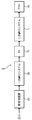
- FIG. 2 is a block diagram schematically showing an ultrapure water production system including the ultrapure water production apparatus 1 shown in FIG. 1 as a secondary pure water system.
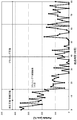
- it is a graph which shows the relationship between elapsed time and the number of microparticles
- it is a graph which shows the relationship between elapsed time and the number of microparticles
- an ultrapure water production apparatus 1 that is an object to be started up and washed according to the present invention has a unit for water treatment downstream of a primary pure water tank (TK) 10 that temporarily stores primary pure water.
- the equipment includes a heat exchanger (HEX) 11 for water temperature control, an ultraviolet oxidation device (TOC-UV) 12 for decomposing organic matter, a membrane degassing device (MDG) 13, and a non-regenerative mixed bed ion exchange resin device.
- HEX heat exchanger
- TOC-UV ultraviolet oxidation device
- MDG membrane degassing device
- Polyisher 14 comprising an ultrafiltration device 15 as a fine particle removing means for removing fine particles.
- the ultrapure water production apparatus 1 is connected to a use point (POU) 16 as a place where ultrapure water is used, and supplies the produced ultrapure water to the use point 16. Further, the ultrapure water production apparatus 1 includes a circulation pipe 19 that circulates ultrapure water that is not used at the use point 16 to the single pure water tank 10.
- the ultrapure water production apparatus 1 is connected to the water treatment unit pipes 17 and the treated water pipes 17 for connecting the water treatment unit units, and the treated water pipes 17.
- a particulate meter 25 for measuring the number of fine particles in the water is connected to the treated water pipe 17 after the ultrafiltration device 15. Further, a drain pipe 18 for discharging water to the outside of the system is connected to the circulation pipe 19 via a three-way valve V2.
- the flow path in the ultrapure water production apparatus 1 is composed of pipes and tubes, in this embodiment, including those in which tanks, pumps, joints, valves, and other equipment are appropriately arranged in the middle of the flow path. This is referred to as a flow path.
- a material constituting the flow path of such water to be treated any material can be used as long as the components are not easily eluted into ultrapure water.
- PVC polyvinyl chloride
- PPS polyphenylene sulfide
- PVDF polyfluoride Vinylidene
- FRP fiber reinforced plastic
- stainless steel or the like
- the method for starting up the ultrapure water production apparatus is as follows in order to remove fine particles adhering to the inner surface of the flow path of the ultrapure water production apparatus 1. In addition, it is performed through a washing step, a de-drug step, and a flushing step.
- the three-way valve V2 is switched from the drain pipe 18 side to the primary pure water tank 10 side, the valve V1 is opened, and the pump P1 is operated. Thereby, the primary pure water (pure water) stored in the primary pure water tank 10 is caused to flow into the ultrapure water production apparatus 1 and further circulated through the circulation pipe 19.
- ultrapure water in a state where primary pure water in which hydrogen peroxide or gas is dissolved (hereinafter also referred to as “gas dissolved water”) is retained or circulated in the flow path of the ultrapure water production apparatus 1. Vibration is applied from the outside to at least a part of the flow path of the water production apparatus 1 (cleaning step).
- vibration energy is given to the fine particles adhering to the inner surface of the flow path, thereby separating the fine particles from the inner surface of the flow path, It can be dispersed and removed. Moreover, peeling of the fine particles from the inner surface of the flow path can be promoted by the gas in the gas-dissolved water becoming bubbles.
- the gas in the primary pure water has the effect of improving the effect of removing fine particles by vibration. That is, as a result of various studies by the present inventors, if the gas in the primary pure water is in a supersaturated state or near supersaturated state, it is thought that the effect of removing fine particles is improved by adding vibration in that state. I understood that. Hydrogen peroxide decomposes in water to become oxygen, which is thought to create a similar situation.
- the gas dissolved in the primary pure water includes nitrogen, hydrogen and carbon dioxide. Of these, nitrogen is preferable.
- the method for dissolving hydrogen peroxide or gas in primary pure water is not particularly limited.
- a method for dissolving the gas there is a method in which the membrane degassing device 13 is used as a gas dissolving device, and the gas is dissolved using the degassing membrane as a dissolving film.
- the upper part of the primary pure water tank 10 is usually hermetically sealed and purged with nitrogen, nitrogen is dissolved in the primary pure water in the primary pure water tank 10. If primary pure water is supplied from the primary pure water tank 10 with the membrane deaerator 13 stopped, nitrogen-dissolved water can be supplied.
- hydrogen peroxide or primary pure water supplied to the ultrapure water production apparatus 1 or primary pure water circulating in the ultrapure water production apparatus 1 system is added to hydrogen peroxide or
- a method of dissolving gas may be used.
- a method of injecting pure water in which hydrogen peroxide or gas is dissolved into the treated water pipe 17 immediately before the unit device or the group of unit devices to be cleaned by a chemical pump or the like may be adopted. it can.
- primary pure water in which hydrogen peroxide or gas is dissolved in advance may be supplied to the ultrapure water production apparatus 1 and circulated in the system.
- the concentration of hydrogen peroxide or gas is not particularly limited as long as it is an amount capable of generating bubbles, but 1 to 3 times the gas dissolved in hydrogen peroxide or gas at that temperature. If it becomes.
- the concentration of hydrogen peroxide or gas is preferably 24 mg / L to 60 mg / L in the case of nitrogen with respect to the primary pure water to be passed. In the case of hydrogen, it is preferably 1.2 mg / L to 3 mg / L. In the case of hydrogen peroxide, it is preferably added at a concentration of 1% by mass to 5% by mass. As a result, the oxygen generated by the decomposition of hydrogen peroxide is in a dissolved state of 8 mg / L to 25 mg / L.
- the bubble is a bubble of several microns to several hundred microns, and can be generated by applying vibration to primary pure water in which the oxygen or gas is dissolved with supersaturation.
- the pressure at the time of supply of the gas dissolved water by the pump P1 is not particularly limited, but it is twice as high as the pressure of primary pure water to the ultrapure water production apparatus 1 at the time of ultrapure water production is 30 to 40% smaller than the pressure.
- the pressure is preferably about the following pressure.
- the pressure at the time of supplying the gas-dissolved water is 2 when the pressure on the permeate side of the ultrafiltration device 15 in the circulation pipe 19 is not less than 30 to 40% smaller than the pressure at the same location during the production of ultrapure water.
- the pressure is preferably about twice or less. If the supply pressure of the gas dissolved water is too small, the concentration of the dissolved water is not sufficient, and the effect of promoting separation of the fine particles from the flow path may be reduced.
- the supply pressure of the gas dissolved water by the pump P1 during the start-up operation is, for example, 0.2 MPa to 0.5 MPa.
- the temperature of the gas-dissolved water circulated in the ultrapure water production apparatus 1 it is preferable to increase the temperature of the gas-dissolved water circulated in the ultrapure water production apparatus 1.
- the water temperature can be raised by stopping this. Further, the water temperature may be raised by supplying a heat source to the heat exchanger.
- the temperature of the dissolved gas flowing through the flow path is preferably 10 ° C to 45 ° C, more preferably 10 ° C to 40 ° C, and further preferably 25 ° C to 40 ° C.
- valve V1 in order to make the gas in the gas dissolved water supersaturated or close to supersaturated, it was installed in the valve V1, the three-way valve V2 or the ultrapure water circulation system when giving the vibration or immediately before giving the vibration. It is preferable to reduce the pressure in the circulatory system by adjusting the opening of other valves or adjusting the output of the pump.
- the flow time of the gas-dissolved water depends on the length and inner diameter of the flow path constituting the ultrapure water production apparatus 1, but may be, for example, 5 minutes to 60 minutes. Further, the flow rate of the gas-dissolved water is not particularly limited, and may be, for example, preferably 0.001 m / s to 3.0 m / s, more preferably 0.5 m / s to 2.0 m / s.
- the discharge pressure of the pump P1 is, for example, equal to or lower than the discharge pressure of the pump P1 when supplying the gas dissolved water, preferably 25 to 75% of the discharge pressure of the pump P1 when supplying the gas dissolved water.
- the gas dissolved water may be circulated in the ultrapure water production apparatus 1 system. This is because if the supply pressure of the dissolved gas at the time of applying vibration is too high, bubbles are not sufficiently generated, and the effect of promoting the separation of the fine particles from the flow path may be reduced.
- you may make gas dissolved water retain in the flow path of the ultrapure water manufacturing apparatus 1, and what is necessary is just to stop the pump P1 in this case.
- the vibration applied to the flow path is preferably 600 gal (Gal) or more, and more preferably 700 Gal or more. Moreover, it is preferable that the vibration given to a flow path is 100,000 Gal or less. This is because the greater the vibration applied to the flow path, the greater the effect of separating the fine particles from the inner surface of the flow path, but if the vibration is too large, the piping may be deteriorated or broken.
- the time for applying the vibration is approximately 1 to 5 minutes, depending on the place and the magnitude of the vibration.
- the method of applying vibration is not particularly limited, and examples thereof include a method of hitting a flow path with a bare hand or a tool such as a wooden hammer or a hammer, a method of applying ultrasonic vibration, and the like.
- the vibration applied to the flow path when struck with a bare hand is 800 Gal or more, 1400 Gal or more for a wooden mallet, and 5000 Gal or more for an ultrasonic wave.
- the vibration given to the flow path can be measured by, for example, a vibration analyzer.
- a connecting portion such as a valve or a joint, a bent pipe portion or a branch portion is preferable. Fine particles are likely to stay and adhere to the connection portion and the inner surface of the flow path of the bent tube portion or the branch portion. According to the start-up method of the present embodiment, excellent peeling and removal effects can be obtained even for such fine particles.
- the place where vibration is applied is preferably a particulate removing means provided in the ultrapure water production apparatus 1, for example, a flow path of the ultrafiltration apparatus 15.
- a microfilter (MF) or a nanofilter (NF) may be provided as the particulate removing means.
- these microfilter (MF) or nanofilter ( NF) may be vibrated.
- the fine particles flowing from the upstream side of the ultrapure water production apparatus 1 may stay and adhere to the inner surface of the flow path of the ultrafiltration device 15 and the fine particle removing means such as the microfilter and nanofilter. It is.
- connection parts such as valves and joints constituting the flow path of the ultrafiltration device 15, and in the bent pipe part or the branch part. Since the retained fine particles are likely to cause a hunting phenomenon at the start of the production of ultrapure water, it is preferable to apply the vibration to such a connection portion or a curved pipe portion.
- the vibration when vibration is applied to the flow path in the apparatus constituting the particulate removing means and the flow path within 1 m before and after (upstream side and downstream side) of the flow path in the apparatus, the vibration is applied. This is more effective for shortening the startup period of the ultrapure water production apparatus 1.
- a bypass pipe (not shown) that bypasses the non-regenerative mixed bed ion exchange resin apparatus 14 is provided to provide a non-regenerative mixed bed ion exchange resin apparatus. 14 is preferably bypassed and gas dissolved water is allowed to flow.
- the vibration is stopped, and then the de-medicating process for discharging the gas dissolved water in the ultrapure water production apparatus 1 is performed.
- primary pure water containing neither hydrogen peroxide nor gas is supplied into the ultrapure water production apparatus 1, and the three-way valve V2 inserted in the circulation pipe 19 is connected to the drain pipe 18 from the primary pure water tank 10 side. Switching to the side, the gas-dissolved water is discharged out of the system via the drain pipe 18, and the de-pharmaceutical process is performed.
- the de-pharmaceutical process is performed for about 30 to 300 minutes, depending on the size of the ultrapure water production apparatus 1 and the flow rate of ultrapure water.
- a flushing process is subsequently performed.
- the flow path is switched from the bypass pipe to the non-regenerative mixed bed ion exchange resin device 14.
- the three-way valve V2 inserted in the circulation pipe 19 is switched from the drain pipe 18 side to the primary pure water tank 10 side to circulate ultrapure water. It is preferable that a part of the ultrapure water circulated in the system in the flushing process is discharged out of the ultrapure water production apparatus 1 system, for example, as concentrated water of the ultrafiltration device 15.
- the fine particle meter 25 it is preferable to continuously measure the fine particles in the ultrapure water with the fine particle meter 25.
- the fine particle meter one that can measure the number of fine particles online is preferable, and for example, UDI-20 manufactured by Particle Measuring Systems can be used.
- the number of fine particles is 0 pcs.
- a phenomenon in which the number of fine particles temporarily increases intermittently occurs. This is presumed to be because there is an insufficiently cleaned portion in the flow path, and fine particles are discharged from this portion.
- the quality of ultrapure water deteriorates, it may be necessary to continue flushing until the hunting phenomenon is reduced without starting production of ultrapure water.
- FIG. 2 is a block diagram schematically showing an ultrapure water production system 2 including the ultrapure water production apparatus 1 shown in FIG. 1 as a secondary pure water system.
- the ultrapure water production system 2 includes a pretreatment device 20 and a primary pure water system 30.
- a primary pure water tank 10 is connected to the subsequent stage of the primary pure water system 30, and an ultrapure water production apparatus (secondary pure water system) 1 is connected through the primary pure water tank 10.
- Production of ultrapure water by the ultrapure water production system 2 is performed as follows.
- raw water such as city water, well water, and industrial water is sequentially processed by the pretreatment device 20 and the primary pure water system 30 to produce primary pure water.
- the pretreatment device 20 is a device that clarifies raw water to produce pretreatment water, and includes, for example, a coagulating sedimentation device and a sand filtration device.
- the primary pure water system 30 is for producing primary pure water by treating pretreated water, and includes an activated carbon device, a reverse osmosis membrane device, a cation exchange resin device, an anion exchange resin device, and a two-bed three-column ion.
- An exchange resin device, a vacuum deaeration device, an ultraviolet oxidation device, a mixed bed ion exchange resin device, a precision filter, and the like are appropriately selected.
- the primary pure water has a specific resistance value of 17 M ⁇ ⁇ cm or more, a TOC concentration of 3 ⁇ g C / L or less, and the number of fine particles of 0.02 ⁇ m or more is 1 pcs. / ML or less.
- the primary pure water is temporarily stored in the primary pure water tank 10 and then supplied to the secondary pure water system 1 (the ultrapure water production apparatus 1 shown in FIG. 1), where ultrapure water is produced. Is done.
- the produced ultrapure water is supplied to the use point 16.
- the fine particles adhering to the inner surface of the flow path of the secondary pure water system 1 are removed by the startup method of the above embodiment, even after the production of ultra pure water is started.
- the specific resistance value is 18.2 M ⁇ ⁇ cm or more
- the TOC concentration is 1 ⁇ g C / L or less
- the number of fine particles is 1 pcs.
- Ultrapure water in which water quality of / mL or less is stably maintained can be supplied to the use point 16.
- a circulation piping system provided in a general ultrapure water production system, that is, a cleaning of a flow path of an ultrapure water production apparatus having a circulation piping for supplying ultrapure water to a POU (use place).
- the present invention is not limited to this.
- a primary pure water production apparatus provided on the upstream side of the primary pure water tank 10 or a tertiary pure water provided on the downstream side of the ultrapure water production apparatus described above as necessary. The same can be applied to the start-up of the water production apparatus.
- Example 1 A start-up operation was performed as follows using a secondary pure water system similar to the ultrapure water production apparatus shown in FIG.
- a bypass pipe that bypasses the non-regenerative mixed bed ion exchange resin apparatus was provided to bypass the non-regenerative mixed bed ion exchange resin apparatus. Open the valve installed downstream of the primary pure water tank and operate the pump on the downstream side of the primary pure water tank to flow the primary pure water stored in the primary pure water tank into the secondary pure water system. It was. At this time, a circulation pipe for connecting the primary pure water tank from the use point was provided to circulate the primary pure water to the primary pure water tank. The discharge pressure of the pump was 0.3 MPa.
- a branch pipe is provided at the inlet side of the heat exchanger, and a chemical injection pump is connected to this, and the ultrapure water (hydrogen peroxide solution) in which hydrogen peroxide is dissolved by this chemical injection pump is used as the primary.
- the ultrapure water hydrogen peroxide solution
- the discharge pressure of the pump when supplying hydrogen peroxide was 0.3 MPa. Thereafter, the supply of hydrogen peroxide was stopped. Primary pure water circulation operation continued.
- the supply water side, permeate side piping, valves, and branches of the flow path provided in the ultrafiltration device of the secondary pure water system were struck with a mallet to give vibration.
- the vibration was applied for 5 minutes, and the vibration by the wooden mallet was 1400 Gal as measured by a digital vibrometer OH-580A (manufactured by Testo Inc.).
- the discharge pressure of the pump was not changed and was set to 0.3 MPa.
- the three-way valve of the circulation pipe is switched from the primary pure water tank side to the drain pipe side, and ultrapure water containing hydrogen peroxide is drained out of the system.
- the primary pure water was supplied into the secondary pure water system, and the secondary pure water system was rinsed to carry out the de-drug process.
- the bypass pipe is switched to water flow to a non-regenerative mixed bed ion exchange resin apparatus, the three-way valve is switched from the drain pipe side to the primary pure water tank side, and the flushing process is performed for 60 hours. Started production of pure water.
- the pump discharge pressure during the production of ultrapure water was 0.3 MPa.
- the number of fine particles of 0.02 ⁇ m or more in the ultrapure water after the start of the flushing process was measured, and the number of occurrences of the hunting phenomenon on the second day, the fourth day, and the seventh day was measured.
- the results are shown in Table 1 together with the startup operation conditions.
- the number of fine particles of 0.02 ⁇ m or more increased compared to the previous and subsequent periods, and the number of times was counted as a hunting phenomenon.
- the number of fine particles during the hunting phenomenon is, for example, 10 pcs. / L or more.
- Example 2 In this example, the start-up operation was performed in the same manner as in Example 1 except that the method of applying vibration to the flow path was changed from the method of hitting with a mallet to the method of hitting with a bare hand. The vibration was applied for 5 minutes, and the vibration when struck with a bare hand was 800 Gal as measured by the above-mentioned digital vibrometer.
- Example 3 In this example, the method of applying vibration to the flow path was changed to a method of applying ultrasonic waves with an ultrasonic generator ET-30S-7 (manufactured by Shimada Rika Kogyo Co., Ltd.), and started up in the same manner as in Example 1. Drove. The vibration was applied for 5 minutes, and the ultrasonic vibration was 5000 Gal as measured by the digital vibration meter.
- ET-30S-7 manufactured by Shimada Rika Kogyo Co., Ltd.
- Examples 4 to 11, Comparative Examples 1 to 8 The startup operation was performed in the same manner as in Example 1 except that the startup operation conditions were changed as shown in Table 1.
- the heat exchanger was operated as necessary to heat the primary pure water to the temperature shown in Table 1.
- the startup operation was performed while operating the deaeration membrane device.
- the primary which dissolved nitrogen Pure water was passed through the channel.
- Example 1 After the start-up operation, production of ultrapure water was started in the same manner as in Example 1, and 0.02 ⁇ m or more in the produced ultrapure water on the second, fourth and seventh days after the start of the flushing process.
- Table 1 together with Example 1 shows the results of measuring the number of fine particles and measuring the number of occurrences of the hunting phenomenon.
- the hunting phenomenon is suppressed and the number of fine particles is 1 pcs. It can be seen that ultrapure water stably maintained at / mL or less was obtained. On the other hand, in Comparative Examples 1 to 8, it can be seen that the hunting phenomenon is not suppressed.
- SYMBOLS 1 Ultrapure water production apparatus (secondary pure water system), 2 ... Ultrapure water production system, 10 ... Primary pure water tank (TK), 11 ... Heat exchanger (HEX), 12 ... Ultraviolet oxidizer (TOC- UV), 13 ... Membrane type deaerator (MDG), 14 ... Non-regenerative mixed-bed ion exchange resin device (Polisher), 15 ... Ultrafiltration device (UF), 16 ... Use point (POU), 17 ... Treated water piping, 18 ... blow piping, 19 ... circulation piping, 20 ... pretreatment device, 30 ... primary pure water system, 25 ... particulate meter, P1 ... pump, V1 ... valve, V2 ... three-way valve.
Landscapes
- Engineering & Computer Science (AREA)
- Water Supply & Treatment (AREA)
- Chemical & Material Sciences (AREA)
- Hydrology & Water Resources (AREA)
- Environmental & Geological Engineering (AREA)
- Organic Chemistry (AREA)
- Life Sciences & Earth Sciences (AREA)
- Chemical Kinetics & Catalysis (AREA)
- General Chemical & Material Sciences (AREA)
- Mechanical Engineering (AREA)
- Health & Medical Sciences (AREA)
- Toxicology (AREA)
- Separation Using Semi-Permeable Membranes (AREA)
- Physical Water Treatments (AREA)
- Cleaning In General (AREA)
- Cleaning By Liquid Or Steam (AREA)
Abstract
L'invention porte sur un procédé de mise en route d'un appareil de production d'eau ultrapure (1) qui permet de supprimer le phénomène de recherche d'un nombre de particules fines après la mise en route de la production d'eau ultrapure et d'obtenir de manière stable de l'eau ultrapure ayant une concentration extrêmement faible de particules fines. L'invention porte également sur un procédé de mise en route d'un appareil de production d'eau ultrapure (1) qui consiste à nettoyer un système interne de l'appareil de production d'eau ultrapure (1) avant d'envoyer l'eau ultrapure dans une section d'utilisation d'un appareil de production d'eau ultrapure (1) afin de traiter l'eau pure de base pour produire l'eau ultrapure et l'envoyer dans la section d'utilisation, l'eau pure contenant du peroxyde d'hydrogène ou un gaz étant amenée à s'accumuler ou à s'écouler dans un canal d'écoulement de l'appareil de production d'eau ultrapure (1); une vibration est transmise de l'extérieur à au moins une partie du canal d'écoulement, et des particules fines adhérant à une surface intérieure du canal d'écoulement sont éliminées.
Priority Applications (2)
| Application Number | Priority Date | Filing Date | Title |
|---|---|---|---|
| KR1020187031072A KR20190005843A (ko) | 2016-05-06 | 2017-05-01 | 초순수 제조 장치의 기동 방법 |
| CN201780027457.3A CN109153047A (zh) | 2016-05-06 | 2017-05-01 | 超纯水制造装置的启动方法 |
Applications Claiming Priority (2)
| Application Number | Priority Date | Filing Date | Title |
|---|---|---|---|
| JP2016-093121 | 2016-05-06 | ||
| JP2016093121A JP2017200683A (ja) | 2016-05-06 | 2016-05-06 | 超純水製造装置の立ち上げ方法 |
Publications (1)
| Publication Number | Publication Date |
|---|---|
| WO2017191829A1 true WO2017191829A1 (fr) | 2017-11-09 |
Family
ID=60203670
Family Applications (1)
| Application Number | Title | Priority Date | Filing Date |
|---|---|---|---|
| PCT/JP2017/017139 Ceased WO2017191829A1 (fr) | 2016-05-06 | 2017-05-01 | Procédé de mise en route d'un appareil de production d'eau ultrapure |
Country Status (4)
| Country | Link |
|---|---|
| JP (1) | JP2017200683A (fr) |
| KR (1) | KR20190005843A (fr) |
| CN (1) | CN109153047A (fr) |
| WO (1) | WO2017191829A1 (fr) |
Cited By (2)
| Publication number | Priority date | Publication date | Assignee | Title |
|---|---|---|---|---|
| CN111108069A (zh) * | 2018-02-07 | 2020-05-05 | 栗田工业株式会社 | 超纯水制造系统的微粒管理方法 |
| JP2021020172A (ja) * | 2019-07-29 | 2021-02-18 | オルガノ株式会社 | 超純水又はガス溶解水供給システムの製造方法並びに洗浄方法 |
Families Citing this family (3)
| Publication number | Priority date | Publication date | Assignee | Title |
|---|---|---|---|---|
| SE542591C2 (en) * | 2018-10-24 | 2020-06-09 | Nanosized Sweden Ab | Method and arrangement for semiconductor manufacturing |
| CN112796143B (zh) * | 2021-02-03 | 2022-10-04 | 远通纸业(山东)有限公司 | 一种使用双氧水对细小纤维进行调色的系统及方法 |
| JP7033691B1 (ja) * | 2021-10-29 | 2022-03-10 | 野村マイクロ・サイエンス株式会社 | 温超純水製造システムの立ち上げ方法、立ち上げプログラム、及び温超純水製造システム |
Citations (2)
| Publication number | Priority date | Publication date | Assignee | Title |
|---|---|---|---|---|
| JP2002151459A (ja) * | 2000-11-10 | 2002-05-24 | Kurita Water Ind Ltd | 洗浄方法 |
| JP2014000548A (ja) * | 2012-06-20 | 2014-01-09 | Nomura Micro Sci Co Ltd | 超純水製造システムの立ち上げ時の洗浄方法 |
Family Cites Families (8)
| Publication number | Priority date | Publication date | Assignee | Title |
|---|---|---|---|---|
| JPS62244483A (ja) * | 1986-04-16 | 1987-10-24 | 川崎重工業株式会社 | 配管の洗浄方法 |
| JPH03288583A (ja) * | 1990-04-03 | 1991-12-18 | Nomura Micro Sci Kk | 純水製造システムにおける配管類の洗浄方法 |
| JP2002052322A (ja) | 2000-08-10 | 2002-02-19 | Kurita Water Ind Ltd | 洗浄方法 |
| JP4480061B2 (ja) * | 2002-10-03 | 2010-06-16 | オルガノ株式会社 | 超純水製造装置及び該装置における超純水製造供給システムの洗浄方法 |
| JP4449080B2 (ja) | 2005-04-15 | 2010-04-14 | オルガノ株式会社 | 超純水製造供給装置の洗浄方法 |
| KR101407831B1 (ko) * | 2007-03-30 | 2014-06-17 | 쿠리타 고교 가부시키가이샤 | 초순수 제조 시스템의 세정 살균 방법 |
| JP4893426B2 (ja) * | 2007-04-02 | 2012-03-07 | パナソニック株式会社 | 超音波洗浄装置および同装置を用いた食器洗い機 |
| JP2011088979A (ja) * | 2009-10-21 | 2011-05-06 | Panasonic Electric Works Co Ltd | 洗浄液、洗浄方法、洗浄液製造装置 |
-
2016
- 2016-05-06 JP JP2016093121A patent/JP2017200683A/ja active Pending
-
2017
- 2017-05-01 WO PCT/JP2017/017139 patent/WO2017191829A1/fr not_active Ceased
- 2017-05-01 KR KR1020187031072A patent/KR20190005843A/ko not_active Ceased
- 2017-05-01 CN CN201780027457.3A patent/CN109153047A/zh not_active Withdrawn
Patent Citations (2)
| Publication number | Priority date | Publication date | Assignee | Title |
|---|---|---|---|---|
| JP2002151459A (ja) * | 2000-11-10 | 2002-05-24 | Kurita Water Ind Ltd | 洗浄方法 |
| JP2014000548A (ja) * | 2012-06-20 | 2014-01-09 | Nomura Micro Sci Co Ltd | 超純水製造システムの立ち上げ時の洗浄方法 |
Cited By (3)
| Publication number | Priority date | Publication date | Assignee | Title |
|---|---|---|---|---|
| CN111108069A (zh) * | 2018-02-07 | 2020-05-05 | 栗田工业株式会社 | 超纯水制造系统的微粒管理方法 |
| JP2021020172A (ja) * | 2019-07-29 | 2021-02-18 | オルガノ株式会社 | 超純水又はガス溶解水供給システムの製造方法並びに洗浄方法 |
| JP7387320B2 (ja) | 2019-07-29 | 2023-11-28 | オルガノ株式会社 | 超純水又はガス溶解水供給システムの製造方法並びに洗浄方法 |
Also Published As
| Publication number | Publication date |
|---|---|
| JP2017200683A (ja) | 2017-11-09 |
| CN109153047A (zh) | 2019-01-04 |
| KR20190005843A (ko) | 2019-01-16 |
Similar Documents
| Publication | Publication Date | Title |
|---|---|---|
| TWI491566B (zh) | Wash sterilization method of ultra pure water manufacturing system | |
| KR101514863B1 (ko) | 전자 재료용 세정수, 전자 재료의 세정 방법 및 가스 용해수의 공급 시스템 | |
| WO2017191829A1 (fr) | Procédé de mise en route d'un appareil de production d'eau ultrapure | |
| CN109564864B (zh) | 电子设备洗涤用的碱水的制造装置及制造方法 | |
| TWI721213B (zh) | 基板洗淨裝置及基板洗淨方法 | |
| TW201902562A (zh) | 中空纖維薄膜裝置之清洗方法、超過濾透膜裝置、超純水製造裝置及中空纖維薄膜裝置之清洗裝置 | |
| JP2014000548A (ja) | 超純水製造システムの立ち上げ時の洗浄方法 | |
| JP5381781B2 (ja) | 超純水製造システムの洗浄方法 | |
| JP2016185520A (ja) | 逆浸透膜装置の薬品洗浄方法及び薬品洗浄装置 | |
| JP2002151459A (ja) | 洗浄方法 | |
| JP5320665B2 (ja) | 超純水製造装置および方法 | |
| TWI699245B (zh) | 超純水製造系統的洗淨方法 | |
| JP4867180B2 (ja) | 浸漬型膜分離装置及びその薬品洗浄方法 | |
| JP3620577B2 (ja) | 超純水製造システムの洗浄方法 | |
| JP3473465B2 (ja) | 膜の洗浄方法 | |
| JP4747659B2 (ja) | 超純水製造供給装置の洗浄方法 | |
| JP2022187148A (ja) | 水処理装置の立上げ方法および洗浄方法 | |
| JP7764927B1 (ja) | 電子デバイス用洗浄水の製造装置および該洗浄水の製造方法 | |
| JP7387320B2 (ja) | 超純水又はガス溶解水供給システムの製造方法並びに洗浄方法 | |
| JP2004026987A (ja) | 超純水製造システムの洗浄方法 | |
| JP2007260211A (ja) | 超純水製造システムの殺菌洗浄方法 | |
| CN116710193A (zh) | 过滤膜的清洗装置、水处理装置和过滤膜的清洗方法 | |
| JP2004113973A (ja) | 純水製造装置の洗浄方法 |
Legal Events
| Date | Code | Title | Description |
|---|---|---|---|
| ENP | Entry into the national phase |
Ref document number: 20187031072 Country of ref document: KR Kind code of ref document: A |
|
| NENP | Non-entry into the national phase |
Ref country code: DE |
|
| 121 | Ep: the epo has been informed by wipo that ep was designated in this application |
Ref document number: 17792761 Country of ref document: EP Kind code of ref document: A1 |
|
| 122 | Ep: pct application non-entry in european phase |
Ref document number: 17792761 Country of ref document: EP Kind code of ref document: A1 |